MS3 and wiring in a knock sensor unit
 12-26-2012, 09:26 PM
#1
Junior Member
Thread Starter
iTrader: (5)

Join Date: Nov 2010
Location: Maine
Posts: 400
Total Cats: -19
Hey guys,
Hoping someone will chime in soon on this. I'm finshing up installing a knock sensor module into my MS3. I've run into a stopping point and need some input. I need to wire up the K1 & K2 pads on the knock sensor module to the mainboard. I just can't figure out where to connect the two wires. I've read the forums, I've read the install page from DIY.
Any help will be great, pics are even better
I have mainboard version 3.0
MS3 basic board 1.3
MSX daughter board
Thanks,
Drew

Reply
 0
0

0
12-26-2012, 09:39 PM
#3
Junior Member
Thread Starter
iTrader: (5)
Join Date: Nov 2010
Location: Maine
Posts: 400
Total Cats: -19
Ok, I guess my next question is, is this in the wiring harness? Is the K1 soldered to the mainboard like the install states, if so, where.
I've read the link you posted, is states that the K1 and K2 wires goes to the knock sensor inputs, those look like they go the db15 pins 10 (K1) and pin 11 (K2). But I don't have a DB15 on the mainboard.
I've read the link you posted, is states that the K1 and K2 wires goes to the knock sensor inputs, those look like they go the db15 pins 10 (K1) and pin 11 (K2). But I don't have a DB15 on the mainboard.
Reply
0
0
12-26-2012, 09:47 PM
#4
Boost Czar


iTrader: (62)
Join Date: May 2005
Location: Chantilly, VA
Posts: 79,493
Total Cats: 4,080
use the spare inputs 1-4 on your mainboard.
for example, in your harness, you could wire the knock sensor to spare 1 and spare 2.
you can then run, inside the MS, spare 1 to k1 and spare 2 to ground.
for example, in your harness, you could wire the knock sensor to spare 1 and spare 2.
you can then run, inside the MS, spare 1 to k1 and spare 2 to ground.
Reply
0
0
 12-27-2012, 10:14 AM
#8
Junior Member
Thread Starter
iTrader: (5)
Join Date: Nov 2010
Location: Maine
Posts: 400
Total Cats: -19
No, rev built me a msm ms3 unit. I know its simple stuff here, just want to do it right and not guess at it and possibly be wrong. I guess my question needs to be detailed a bit more. Since the knock sensor is wired into the factory harness, what pin do I need to connect to the pigtail harness between the oem connectors and the MS3, I have no problem doing the wiring, but I don't know what pin from the oem harness needs to be connected to the "spare" or open pin on the MS3 harness. I'm not trying to reinvent the wheel here, just trying to figure out what pin from the oem wiring harness I need to use to run into the MS3 harness and then in turn solder from the DB connector to the K1 & K2 pads on the knock sensor board.
Reply
0
0
 12-27-2012, 10:52 AM
#10
Elite Member
iTrader: (10)
Join Date: Jun 2006
Location: Athens, Greece
Posts: 5,977
Total Cats: 356
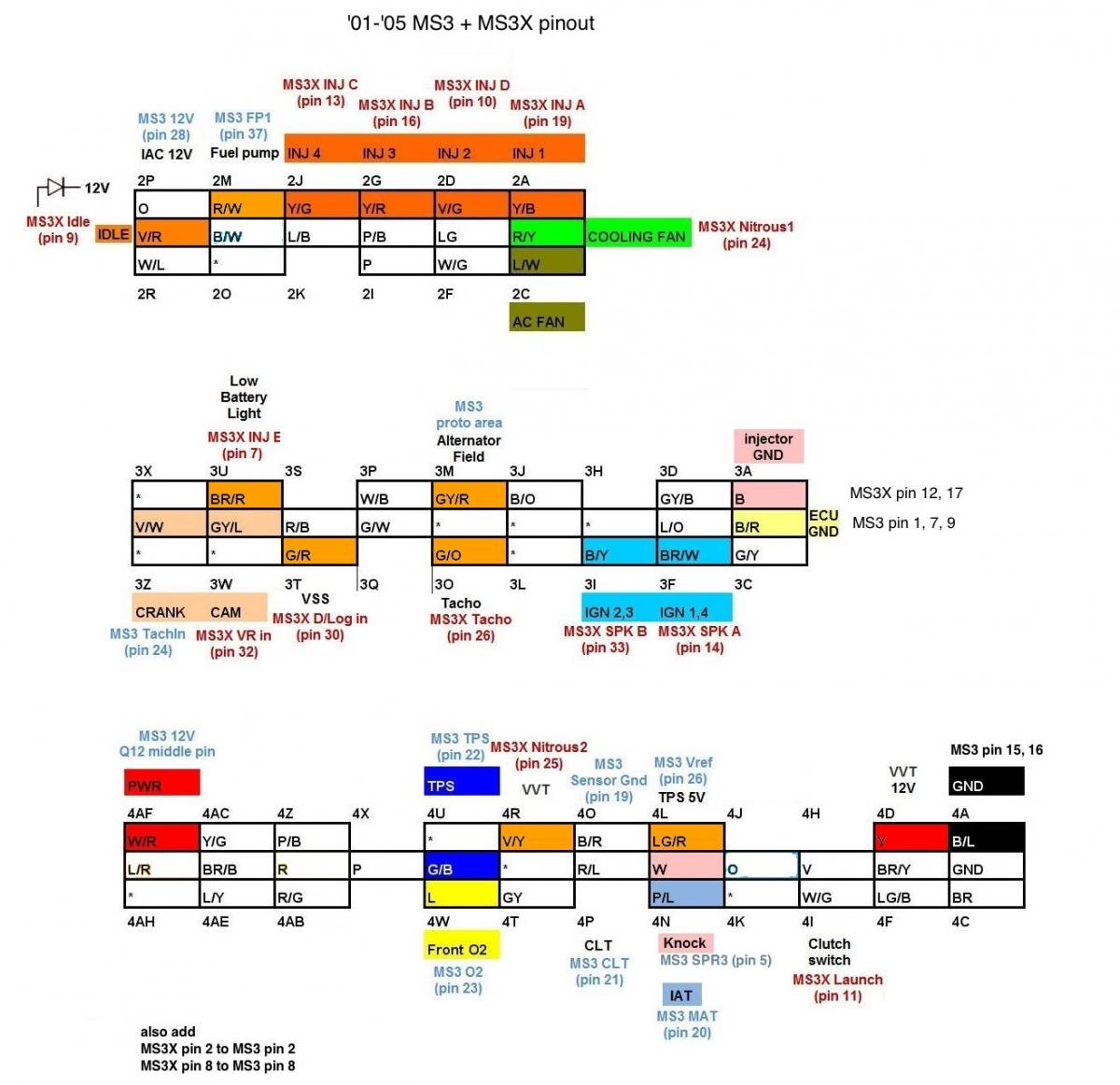
Connect K1 to SPR4.
Then connect pin #6 on the bottom 37-way connector of the MS to pin 4M on the OEM harness.
You didn't tell me that you were going to install the knock module or I would have prewired everything for you.
Then connect pin #6 on the bottom 37-way connector of the MS to pin 4M on the OEM harness.
You didn't tell me that you were going to install the knock module or I would have prewired everything for you.
Reply
0
0
12-27-2012, 02:03 PM
#11
Junior Member
Thread Starter
iTrader: (5)
Join Date: Nov 2010
Location: Maine
Posts: 400
Total Cats: -19
Thanks Rev,
That's what I needed to know. I reviewed our emails and I did talk to you about me adding the knock sensor and compatibility with the new board. No big deal, I'll use your info and wire it up. Thank you again for everything.

That's what I needed to know. I reviewed our emails and I did talk to you about me adding the knock sensor and compatibility with the new board. No big deal, I'll use your info and wire it up. Thank you again for everything.
Reply
0
0
12-27-2012, 02:33 PM
#13
Junior Member
Thread Starter
iTrader: (5)
Join Date: Nov 2010
Location: Maine
Posts: 400
Total Cats: -19
No big deal. as for a white wire, no. I have red, yellow, gray, brown, and green. I just ran the wire from K1 to SPR4 and disassembled the MS end connector and see that pin 4 is free for use, but I noticed that the oem end of the cable is epoxied, so access the the pins is not available. I figured I'd just have to tap into the original wire. Any info on color or location on the oem connection from the car?
Reply
0
0

Thread
Thread Starter
Forum
Replies
Last Post
Zaphod
MEGAsquirt
47
10-26-2018 11:00 PM
StratoBlue1109
Miata parts for sale/trade
21
09-30-2018 01:09 PM


