Disable alternator field
 09-15-2013, 10:17 AM
#1
Senior Member
Thread Starter

Join Date: Nov 2007
Location: Belgium
Posts: 999
Total Cats: 73
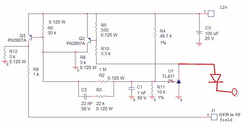
I want to add a way to turn of the alternator while cranking so I figured I'd try and use DIY's fuel pump drive circuit to turn it off.
Doesn't seem to work though (it never turns off) so I could use some help .
.
Doesn't seem to work though (it never turns off) so I could use some help
.
Last edited by WestfieldMX5; 09-20-2013 at 04:05 PM.

Reply
 0
0

0
09-15-2013, 12:37 PM
#3
Senior Member
iTrader: (1)

Join Date: Sep 2011
Location: Lambertville, NJ
Posts: 1,215
Total Cats: 74
A general thought here: This circuit is not like a relay (switch). All it can really do is connect something to +12V. It may work if the field out signal is pwm, but if it's an analog signal, this circuit probably won't help.
Where does the 'field in' come from?
Where does the 'field in' come from?
Reply
0
0
09-15-2013, 02:35 PM
#4
Senior Member
Thread Starter
Join Date: Nov 2007
Location: Belgium
Posts: 999
Total Cats: 73
field in comes from Jason's alternator circuit. I just route J1 to the input of the circuit above.
Me thinks this should work. It doesn't of course ;(
Me thinks this should work. It doesn't of course ;(
Last edited by WestfieldMX5; 09-20-2013 at 04:07 PM.
Reply
0
0
09-15-2013, 03:04 PM
#5
Senior Member
iTrader: (1)
Join Date: Sep 2011
Location: Lambertville, NJ
Posts: 1,215
Total Cats: 74
I assume we must have some voltage at J1 for the alternator to put out current. If so, I would just use an NPN transistor or MOSFET to pull J1 to ground for disabling the alternator. Much simpler circuit. I can draw you a schematic if needed.
If you ground J1, do you get a drop in Voltage? If so, my suggestion should work. There's a 1KOhm resistor (R9) in the line to J1, so pulling it to ground shouldn't cause any trouble. At worst you'd get 13mA or so through R9.
If you ground J1, do you get a drop in Voltage? If so, my suggestion should work. There's a 1KOhm resistor (R9) in the line to J1, so pulling it to ground shouldn't cause any trouble. At worst you'd get 13mA or so through R9.
Reply
0
0
09-15-2013, 07:32 PM
#6
2 Props,3 Dildos,& 1 Cat


iTrader: (8)
Join Date: Jun 2005
Location: Fake Virginia
Posts: 19,338
Total Cats: 573
oh oh i did this and hooked it to a GPO!
I believe it was just a simple tip125. You use it like you would any other positive voltage output but instead of hooking it to a 12v source, you hook it to the alternator field output of jason's circuit.
if I can find a photo/drawing of mine I'll post it.
I believe it was just a simple tip125. You use it like you would any other positive voltage output but instead of hooking it to a 12v source, you hook it to the alternator field output of jason's circuit.
if I can find a photo/drawing of mine I'll post it.
Reply
0
0
09-15-2013, 07:40 PM
#7
2 Props,3 Dildos,& 1 Cat
iTrader: (8)
Join Date: Jun 2005
Location: Fake Virginia
Posts: 19,338
Total Cats: 573
well that was easy:
[image deleted to avoid confusing people with the hard way]
not sure this is exactly as I implemented it but I think so. The little circle with an X is the alternator (i.e. ignore it). the box in the upper right is Jason's circuit. The left "uC" is a megasquirt output. I think I used one of the ones on the main board that doesn't come out to the connector.
Last edited by y8s; 09-20-2013 at 05:16 PM.
Reply
0
0
09-15-2013, 09:53 PM
#8
Boost Pope
iTrader: (8)
Join Date: Sep 2005
Location: Chicago. (The less-murder part.)
Posts: 33,019
Total Cats: 6,587
1: Presupposing that the field drive signal is current-limited at the source, why not use a single NPN to pull it to ground?
2: Does the alternator really produce a measurable load on the crank while the engine is turning at ~300 RPM? We know empirically that its voltage outputs drops to below vBatt at ~600 RPM or so, regardless of field drive.
2: Does the alternator really produce a measurable load on the crank while the engine is turning at ~300 RPM? We know empirically that its voltage outputs drops to below vBatt at ~600 RPM or so, regardless of field drive.
Reply
0
0
09-16-2013, 08:02 AM
#9
Boost Czar

iTrader: (62)
Join Date: May 2005
Location: Chantilly, VA
Posts: 79,490
Total Cats: 4,079
Just use a simple pn2222 to trigger a TIP125 on the field out. Set the output to activate the relay above 300RPM. This is what I did on the alternator PCBs I whipped up; works great.
I failed to add the pn2222 circuit on the board itself, but if I ever redesign it and print more, I'll add that and then switch the TIP125 to a 1A PNP, a TIP125 is overkill, there's no load on the field out.
I failed to add the pn2222 circuit on the board itself, but if I ever redesign it and print more, I'll add that and then switch the TIP125 to a 1A PNP, a TIP125 is overkill, there's no load on the field out.
Reply
0
0
09-16-2013, 10:51 AM
#10
Senior Member
Thread Starter
Join Date: Nov 2007
Location: Belgium
Posts: 999
Total Cats: 73
Seems I have what you and Y8S are using, but without the extra npn. Maybe the base current is too little for the TIP125.
Firsit I'll try with a single npn, pulling down J1 as suggested by Stefan.
Firsit I'll try with a single npn, pulling down J1 as suggested by Stefan.
Reply
0
0
09-16-2013, 11:10 AM
#11
2 Props,3 Dildos,& 1 Cat
iTrader: (8)
Join Date: Jun 2005
Location: Fake Virginia
Posts: 19,338
Total Cats: 573
It makes a big difference in my experience. The load was enough to make my alternator belt squeal every startup. Plus you have to tune all sorts of crazy load cells at 300 rpm. Ideally, it would not charge during cranking and then slowly ramp up the amperage over a few seconds to avoid a post-start idle dip.
Reply
0
0
09-16-2013, 12:27 PM
#12
Boost Pope
iTrader: (8)
Join Date: Sep 2005
Location: Chicago. (The less-murder part.)
Posts: 33,019
Total Cats: 6,587
Not even a resistor, just ground the bitch. Basically, consider how we normally do the spark out on a non-Joe MS. (Again, this presupposes current limiting on the driver, else **** will blow up.)
Last edited by Joe Perez; 09-16-2013 at 01:44 PM.
Reply
0
0
09-18-2013, 11:19 AM
#17
Elite Member

Join Date: Jul 2005
Posts: 6,420
Total Cats: 84
Then try this. This assumes the pulldown goes away after cranking, and is a "clean" pulldown and does no pulling down when it's not supposed to. Verify operation and check voltage regulation at idle with electrical loads on and at 3000 RPM with loads off.
Diode is 1N4148 or 1N4001, resistor is 3.3k.
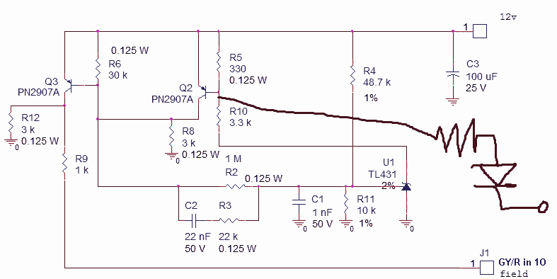
Diode is 1N4148 or 1N4001, resistor is 3.3k.
Reply
0
0