DIY PNP No Start
 02-08-2016, 11:23 PM
#1
Senior Member
Thread Starter

Join Date: Aug 2007
Posts: 574
Total Cats: 44
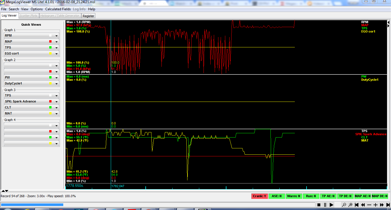
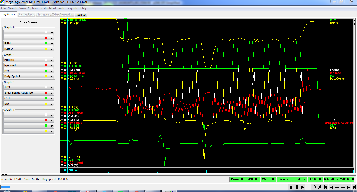
Ok, this is a used DIYPNP that i purchased. The owner said he could not get a good cam signal. It was setup for a 99 but i have changed it for my 1993 1.6(bone stock). I followed the jumpers closely and i think i am in good shape there. I havent had much time to test why it is no start yet(fuel/spark/etc) but i noticed that i am not getting an rpm signal in the datalog. any common problems i should be looking out for? here is my file and screenshot of megalog viewer. This is a v1.5b board and has the 3.4.1 firmware. Im hoping the board is not screwed up from the first guy but the price was worth the hassle.

Reply
 0
0

0
02-09-2016, 10:04 AM
#2

Opto+ and VR have the proper pull ups (down in the corner), right?
I took a look at the optoisolator circuit on the microsquirt and it seems pretty simple, there isn't much that can go wrong if your wiring's right.
The chip has a reverse bias max of 5v, but with the diode on the input that would be pretty difficult to burn up accidentally (maybe that's toast too)
There might be a way to use the VR circuit that the gurus know about. You've always wanted toothed wheel ignition anyway, right?
Reply
0
0
02-09-2016, 06:37 PM
#3
Senior Member
Thread Starter
Join Date: Aug 2007
Posts: 574
Total Cats: 44
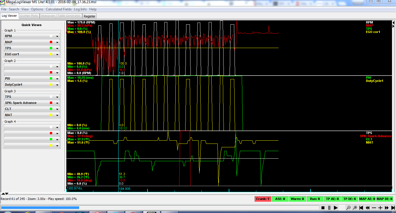
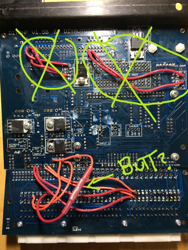
Here are some pictures of the board. I was looking at another topic and saw where miata boards are never supposed to use R39. Original builder had it installed so i have now removed it. I am now getting an oscilating signal for several things and can here the cars Circuit Opening Relay cylcing on and off. I need to locate what is causing the systems to cycle power on and off like that. Here are some screenshots of my board and the logviewer.
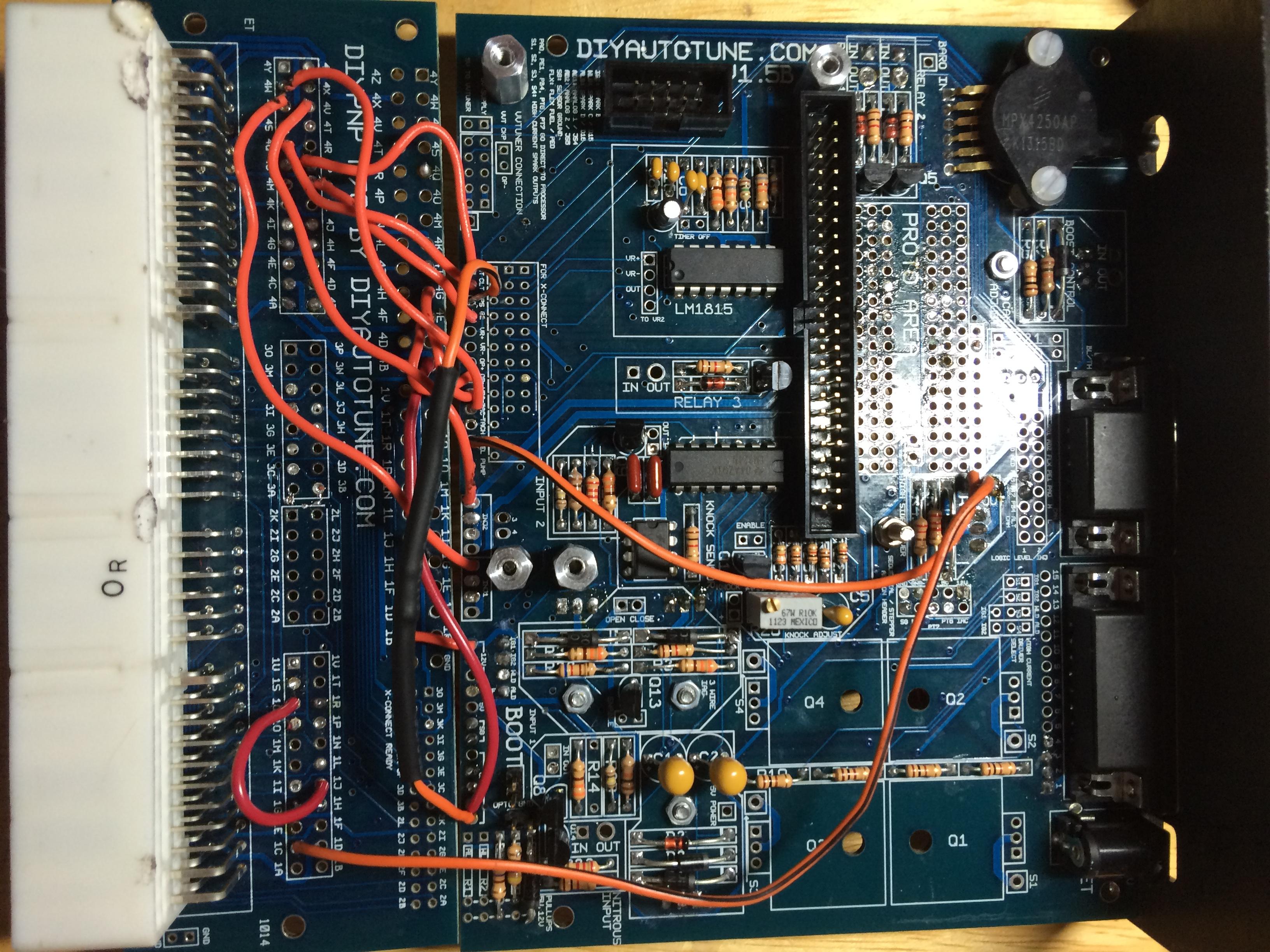
Please ignore the butt connectior, that will be chaged before permenantly installing the module.
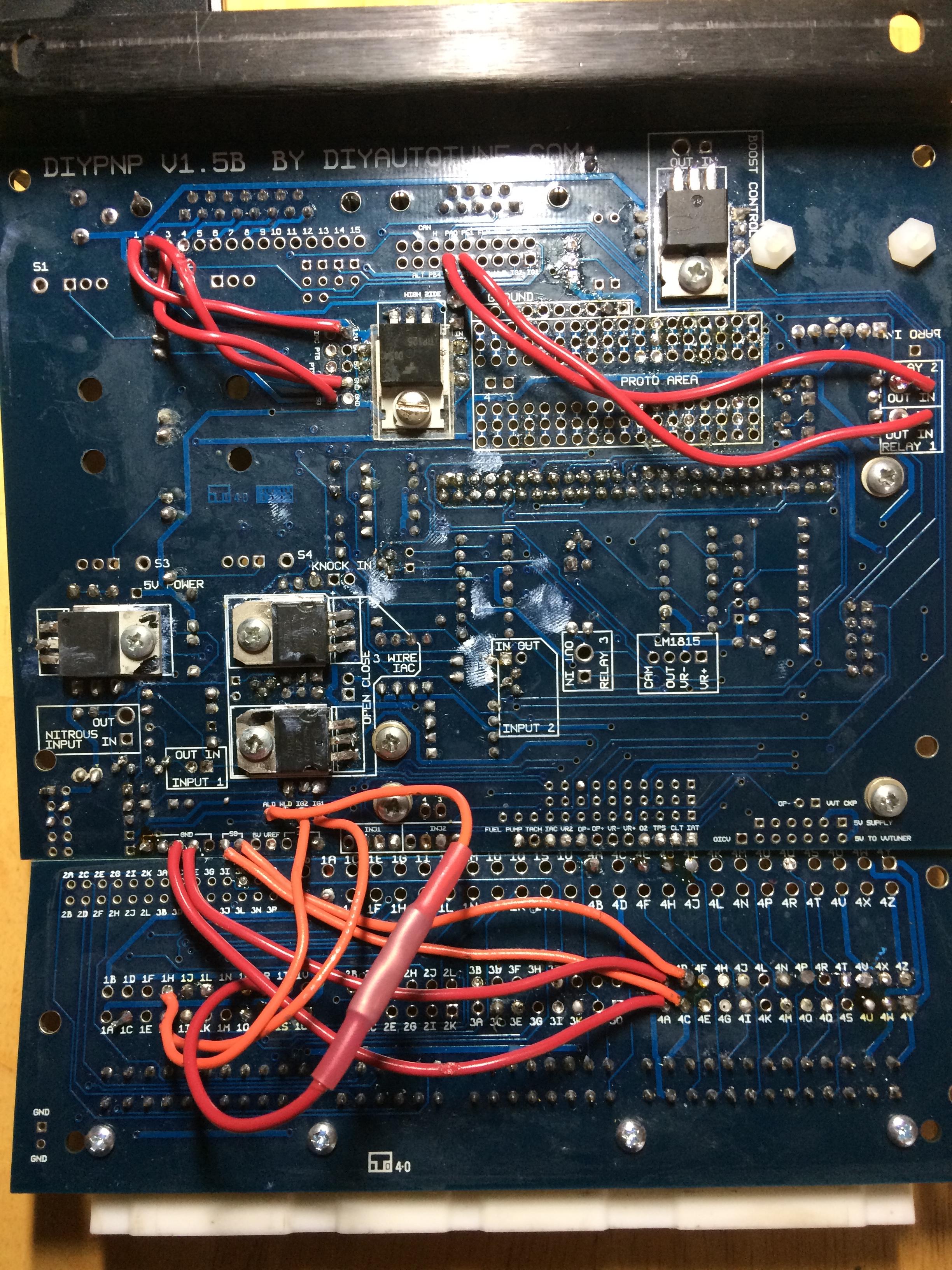
Please ignore the butt connectior, that will be chaged before permenantly installing the module.
Reply
0
0
02-10-2016, 09:21 AM
#8
Senior Member
Thread Starter
Join Date: Aug 2007
Posts: 574
Total Cats: 44
I wish i had a better understanding of what controls each system. For this we are getting fluxuating output to the Circuit Opening relay which comes from 1C on the board. so i bench tested it using the test mode activating the fuel pump. On the board i am getting a solid 12v to 1c with no fluxuation.
So when it installed in the car, it does the initial activation of the pump for priming. that works fine. Once you hit the key to start you get the fluxuations.
With the megasquirt, will it only activate the 1c circuit(after the priming) when it sees engine rpm? If that is the case it points back to the CAS inputs having an issue. I am going to double check all the resistors, diodes, etc when i get home using the diypnp_1.5_bom. outside of that i am not sure of where to go. I am using the standard 90-93 basemap with 240cc injectors and the 4g63 ignition settings. There is also one ground on the chassis that i need to double check. I am not 100% sure it is good and it is the one for Signal Grounds.
Reply
0
0
02-10-2016, 09:43 AM
#10
Senior Member
Thread Starter
Join Date: Aug 2007
Posts: 574
Total Cats: 44
yes, pin 1 of the db15 goes to 12v. that was done by the previous owner. I am not running a wideband o2, just the stock one currently and it is run to 4N. Even though i have nothing hooked to the option port, will that cause me problems? I have no problem going and removing all those connections.
Reply
0
0
02-10-2016, 09:56 AM
#11
Boost Czar


iTrader: (62)
Join Date: May 2005
Location: Chantilly, VA
Posts: 79,488
Total Cats: 4,077
it will cause problems because that circuit cant handle the load from the WBo2 if you power it there.
if you wanna use the DB15, you'd need to jump directly from 1B on the connector board and not through the MS PCB/circuits.
ill go through your pics later and see if i see anything. crank and cam inputs look correct, as do the jumpers, so you should be getting a clean RPM signal so long as youre set to 4G63 and not 99-00 miata.
Reply
0
0
02-10-2016, 11:08 AM
#13
Boost Czar
iTrader: (62)
Join Date: May 2005
Location: Chantilly, VA
Posts: 79,488
Total Cats: 4,077
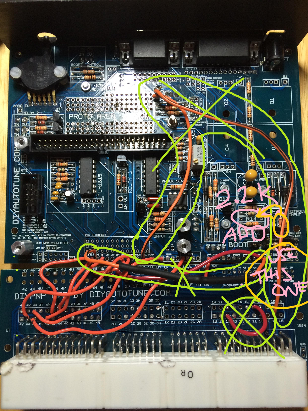


4 thousand words. here's what i would do. the rest looks fine. should run as is.
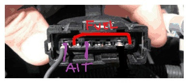
i hate using the high side driver for fueling, i like a jumper wire in the AFM connector and no need to worry about the silly fuse.
Reply
2
2
02-10-2016, 06:27 PM
#17
Senior Member
Thread Starter
Join Date: Aug 2007
Posts: 574
Total Cats: 44
Ok. Here is where i am at.
I have removed all the wiring that was X'ed out other than the tps, will do that shortly.
I did the A/C wiring changes and the fuel pump wire change.
I have not done the boost control, launch control yet as i want to get the initial start squared away before adding extras. I also have not done the vpts prewire and the 2.2k ohm resistor(for the vtps circuit, right?).
I bench tested it and am getting no voltage to 4O, i am getting solid continuity to ground when i activate the pump though. Is that how it is meant to be with your wiring setup brain? I also installed it in the car and get no activation of the pump even at key on.
Reply
0
0
02-10-2016, 07:39 PM
#18
Boost Czar
iTrader: (62)
Join Date: May 2005
Location: Chantilly, VA
Posts: 79,488
Total Cats: 4,077
the fuel pump ground now goes into the AFM connector at 4O (there should be no voltage), just must put a jumper wire on the pin on the AFM that goes back to 4O and then the pin that grounds the fuel pump relay.
normally the AFM flapper--when sucked open during cranking--activates the fuel pump, now the MS is taking full control.
that 2.2K resistor is needed to make input 1 work correctly, thats the a/c switch input.
youll need to turn the a/c idle up on in your msq for the a/c to work now. the input should be pe1 and output WLED.
Reply
1
1
02-10-2016, 07:43 PM
#19
Senior Member
Thread Starter
Join Date: Aug 2007
Posts: 574
Total Cats: 44
Awesome, after looking at the miata schematics i realized that you most likely meant for me to jump the red wire at the maf(4O) to Light Green(back to the fuel pump relay) which would be grounding and activating the relay.
Thanks again for all the help Brain.
Thanks again for all the help Brain.
Reply
0
0
02-11-2016, 04:06 PM
#20
Senior Member
Thread Starter
Join Date: Aug 2007
Posts: 574
Total Cats: 44
Fuel pump circuit works great, i like the method of controlling it with a ground signal rather than voltage. However i am still getting no start and the unusual readings with the rpm and other components. as you can see the battery voltage stays normal except for those droops. the battery is fine and on the charger, i think it is because it is trying to catch at that point causing high load on the system. i am uploading datalog, composite logger and my current msq.
Reply
0
0


