No start, much sadness, 99/00 DIYPNP
 10-06-2012, 03:58 PM
#1
Elite Member
Thread Starter
iTrader: (37)

Join Date: Apr 2010
Location: Very NorCal
Posts: 10,441
Total Cats: 1,899
So the car used to run, now it does not.
I did ONE track day and it straight up died after the last session. I had to get my amazingly patient fiancee to grab my ECU, MAF, IAT and p-p-p0wercard from the garage and bring it 200 miles north so I could get the car running and get it home. This was probably about a month ago.
Today I decided to give the DIYPNP another go. This is the same map that I road tuned for weeks before my track day. I fiddled with it a little bit @ the track, but it still ran fine for 2 sessions after the fiddling. The car is back to COMPLETELY STOCK at this point, other than the Brainy-built DIYPNP. I even jammed the GM IAT into the hole in the side of the stock airbox.
Ok, tell me what to do next. At this point, I feel like science dog:

It will become very obvious that I need things explained like I'm 5. Hopefully this can help others out as well.
As a side note: the car runs 100% with the factory ECU/IAT/MAF installed, but refuses to even pop with the DIYPNP.
Attached is .csv and .msl of (I think) cranking and .msq of current shitty tune that does not start.
Thanks gays, I appriciate the helps
I did ONE track day and it straight up died after the last session. I had to get my amazingly patient fiancee to grab my ECU, MAF, IAT and p-p-p0wercard from the garage and bring it 200 miles north so I could get the car running and get it home. This was probably about a month ago.
Today I decided to give the DIYPNP another go. This is the same map that I road tuned for weeks before my track day. I fiddled with it a little bit @ the track, but it still ran fine for 2 sessions after the fiddling. The car is back to COMPLETELY STOCK at this point, other than the Brainy-built DIYPNP. I even jammed the GM IAT into the hole in the side of the stock airbox.
Ok, tell me what to do next. At this point, I feel like science dog:
It will become very obvious that I need things explained like I'm 5. Hopefully this can help others out as well.
As a side note: the car runs 100% with the factory ECU/IAT/MAF installed, but refuses to even pop with the DIYPNP.
Attached is .csv and .msl of (I think) cranking and .msq of current shitty tune that does not start.
Thanks gays, I appriciate the helps

Reply
 0
0

0
10-06-2012, 07:28 PM
#3
Elite Member
Thread Starter
iTrader: (37)
Join Date: Apr 2010
Location: Very NorCal
Posts: 10,441
Total Cats: 1,899
Thanks Rev, I appreciate you taking a look. Its somewhat obvious now that you've pointed it out.
This DIYPNP is going to be the death of me. Last time this happened, it was a trace on the PCB for the MAP. What can I check with my DMM to confirm?
This DIYPNP is going to be the death of me. Last time this happened, it was a trace on the PCB for the MAP. What can I check with my DMM to confirm?
Reply
0
0
10-07-2012, 02:48 AM
#4
Elite Member
Thread Starter
iTrader: (37)
Join Date: Apr 2010
Location: Very NorCal
Posts: 10,441
Total Cats: 1,899
Ok, so I dug around in the factory wiring diagram and it looks like "2J" is the input for the CKP. "2J" runs into pin 3J on the DIYPNP N76 bridge connector. The 3J is jumped into OP- in the V1.5B mainboard. From there, it runs into the "OPTO GND" jumper where I can get continuity. The jumper is in the "off" position.
According to the "Jumper Configuration," the 99/00 Miata should have:
3J is OPTO IN -
3H is VR2 IN +
470Ω resistor running across OPTO+ R3 to a 12V pullup
470Ω resistor running across VR2 R4 to a 5V pullup
If I'm reading this correctly, I *SHOULD* be getting continuity all the way from 3J through the leg of OPTO+ R3, correct?
For ***** and giggles, I *AM* getting continuity from 3H to VR2 R4.
I suspect the solder joint at R4. If someone can confirm my insanity before I pull out the soldering iron and start burning things, I would be rather grateful.
Reply
0
0
10-07-2012, 03:32 AM
#5
Elite Member

iTrader: (10)
Join Date: Jun 2006
Location: Athens, Greece
Posts: 5,977
Total Cats: 355
Ok, so I dug around in the factory wiring diagram and it looks like "2J" is the input for the CKP. "2J" runs into pin 3J on the DIYPNP N76 bridge connector. The 3J is jumped into OP- in the V1.5B mainboard. From there, it runs into the "OPTO GND" jumper where I can get continuity. The jumper is in the "off" position.
According to the "Jumper Configuration," the 99/00 Miata should have:
3J is OPTO IN -
3H is VR2 IN +
470Ω resistor running across OPTO+ R3 to a 12V pullup
470Ω resistor running across VR2 R4 to a 5V pullup
If I'm reading this correctly, I *SHOULD* be getting continuity all the way from 3J through the leg of OPTO+ R3, correct?
For ***** and giggles, I *AM* getting continuity from 3H to VR2 R4.
I suspect the solder joint at R4. If someone can confirm my insanity before I pull out the soldering iron and start burning things, I would be rather grateful.
According to the "Jumper Configuration," the 99/00 Miata should have:
3J is OPTO IN -
3H is VR2 IN +
470Ω resistor running across OPTO+ R3 to a 12V pullup
470Ω resistor running across VR2 R4 to a 5V pullup
If I'm reading this correctly, I *SHOULD* be getting continuity all the way from 3J through the leg of OPTO+ R3, correct?
For ***** and giggles, I *AM* getting continuity from 3H to VR2 R4.
I suspect the solder joint at R4. If someone can confirm my insanity before I pull out the soldering iron and start burning things, I would be rather grateful.
You should be getting continuity between OP- (and therefor 3J) and pin 21 on the 50way connector of the Microsquirt module.
Reply
0
0
10-07-2012, 11:49 AM
#7
Elite Member
Thread Starter
iTrader: (37)
Join Date: Apr 2010
Location: Very NorCal
Posts: 10,441
Total Cats: 1,899
Thanks again Reverant
I am getting continuity from 3J to pin 21.
The MicroSquirt module diagram looks like pin 21 for the OPTO connects to a bunch of crap, including C27 and C28. C27 is not populated however C28 is. As expected, I can get continuity between C27/C28 and pin 21.
If I'm reading the diagram correctly (and this is a big IF) I should be able to get continuity between C27/C28 and at least one of the legs on U4, per a given side.
this is where I get continuity:
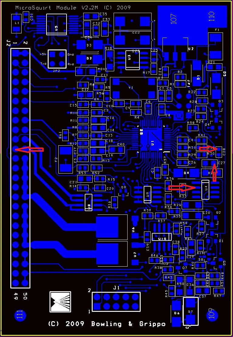
Sorry for the massive picture but I don't know how else to describe what I'm seeing.
So this means I SHOULD be getting getting continuity from any of these points back to J3... except that I definitely am not.
Hi Brain!
R39 (over by BOOST CONTROL?) is not populated
I am getting continuity from 3J to pin 21.
The MicroSquirt module diagram looks like pin 21 for the OPTO connects to a bunch of crap, including C27 and C28. C27 is not populated however C28 is. As expected, I can get continuity between C27/C28 and pin 21.
If I'm reading the diagram correctly (and this is a big IF) I should be able to get continuity between C27/C28 and at least one of the legs on U4, per a given side.
this is where I get continuity:
Sorry for the massive picture but I don't know how else to describe what I'm seeing.
So this means I SHOULD be getting getting continuity from any of these points back to J3... except that I definitely am not.
Hi Brain!
R39 (over by BOOST CONTROL?) is not populated
Last edited by EO2K; 10-07-2012 at 11:50 AM. Reason: lisdexia
Reply
0
0
10-07-2012, 12:25 PM
#8
Elite Member
Thread Starter
iTrader: (37)
Join Date: Apr 2010
Location: Very NorCal
Posts: 10,441
Total Cats: 1,899
So now that I've had coffee this morning, I suspect the pin 21 solder joint.
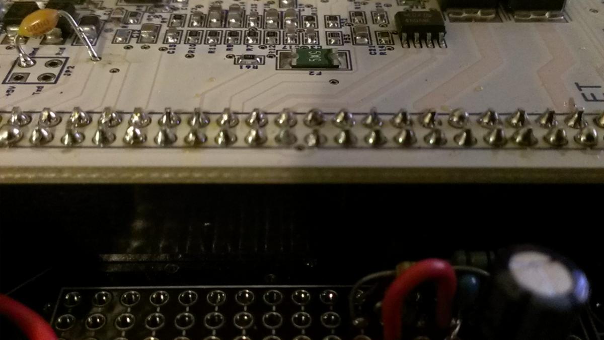
The pic is not that amazing, but you can see its more "grey" and the rest of the pins have a nice "shine" on them. I can hit the tip of the pin or the grey solder ball and get back to J3, but I can't get from the tip or solder ball back to any of the red arrow component pads in the above image.
If I come in from the side of 21, I think I'm hitting the pad on the �S module and I can get continuity to any of the above pads.
Bad solder joint between �S board and pin 21?
Reply
0
0
10-07-2012, 12:49 PM
#10
Elite Member
Thread Starter
iTrader: (37)
Join Date: Apr 2010
Location: Very NorCal
Posts: 10,441
Total Cats: 1,899
Just pulled the entire �S board out of the DIYPNP. From the long pins on the bottom of the �S board male connector, no continuity to the above pads. I'll see if I can get some help resoldering this bitch and try again.
Is this header soldered in @ B&G, or is this something I can raz the about?
I'll check the voltage on 21 tonight when I get home. I'm running out of time today. I need to help a friend change an O2 sensor in a Toyota Camry and then go get dirty with another friend in the middle of an NB1 LS1 swap
Is this header soldered in @ B&G, or is this something I can raz the
about? I'll check the voltage on 21 tonight when I get home. I'm running out of time today. I need to help a friend change an O2 sensor in a Toyota Camry and then go get dirty with another friend in the middle of an NB1 LS1 swap
Reply
0
0
10-07-2012, 01:09 PM
#13
Boost Czar

iTrader: (62)
Join Date: May 2005
Location: Chantilly, VA
Posts: 79,493
Total Cats: 4,080
Problem is it sounds like you're still getting the correct continuity.
pin 21 goes back to U4 and should touch c27 and c28 on the way.
oh yeah, now i remember this MS, we had the weird issue of no MAP signal with yours right? c11 had to be replaced as I found it non-functioning right?
pin 21 goes back to U4 and should touch c27 and c28 on the way.
oh yeah, now i remember this MS, we had the weird issue of no MAP signal with yours right? c11 had to be replaced as I found it non-functioning right?
Reply
0
0
10-07-2012, 01:17 PM
#14
Elite Member
Thread Starter
iTrader: (37)
Join Date: Apr 2010
Location: Very NorCal
Posts: 10,441
Total Cats: 1,899
Correct. No continuity through pin 21 into the �S board. I'm guessing that would obviously cause my no CKP signal, correct?
Not sure how I would check any/all of the other pins. Any chance there is a short list of other things I can check while I have access to a friend who is a ninja with a soldering iron?
Not sure how I would check any/all of the other pins. Any chance there is a short list of other things I can check while I have access to a friend who is a ninja with a soldering iron?
Reply
0
0
10-07-2012, 01:19 PM
#15
Elite Member
Thread Starter
iTrader: (37)
Join Date: Apr 2010
Location: Very NorCal
Posts: 10,441
Total Cats: 1,899
Problem is it sounds like you're still getting the correct continuity.
pin 21 goes back to U4 and should touch c27 and c28 on the way.
oh yeah, now i remember this MS, we had the weird issue of no MAP signal with yours right? c11 had to be replaced as I found it non-functioning right?
pin 21 goes back to U4 and should touch c27 and c28 on the way.
oh yeah, now i remember this MS, we had the weird issue of no MAP signal with yours right? c11 had to be replaced as I found it non-functioning right?
This thing is really turning into a handful.
Reply
0
0
 10-08-2012, 01:57 AM
#19
Elite Member
Thread Starter
iTrader: (37)
Join Date: Apr 2010
Location: Very NorCal
Posts: 10,441
Total Cats: 1,899
Pin 21 is now looking good thanks to Gesso and his awesome soldering skills. Continuity exactly where it should be. I'll give it a test tomorrow afternoon when I get home from work.
Brain: What exactly was up with the C11 thing? Whatever is supposed to be there is completely missing. Did you do that? Is that critical?
Brain: What exactly was up with the C11 thing? Whatever is supposed to be there is completely missing. Did you do that? Is that critical?
Reply
0
0


