PWM converter board at the DIYPNP
 11-07-2009, 03:43 AM
#1
Elite Member
Thread Starter

Join Date: Mar 2006
Location: Schwarzenberg, Germany
Posts: 1,553
Total Cats: 101
Hi,
I just received my PWM converter board and would like to document how I will attach it to the DIYPNP.
1. The placement:
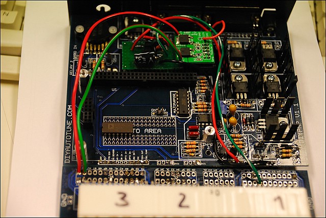
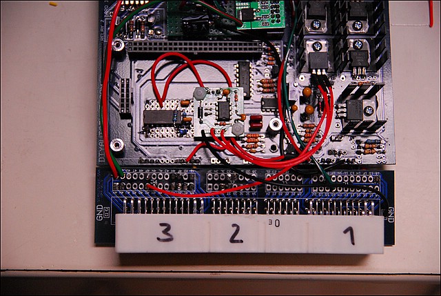
Here is a pic of the DIYPNP without the Microsquirt module:
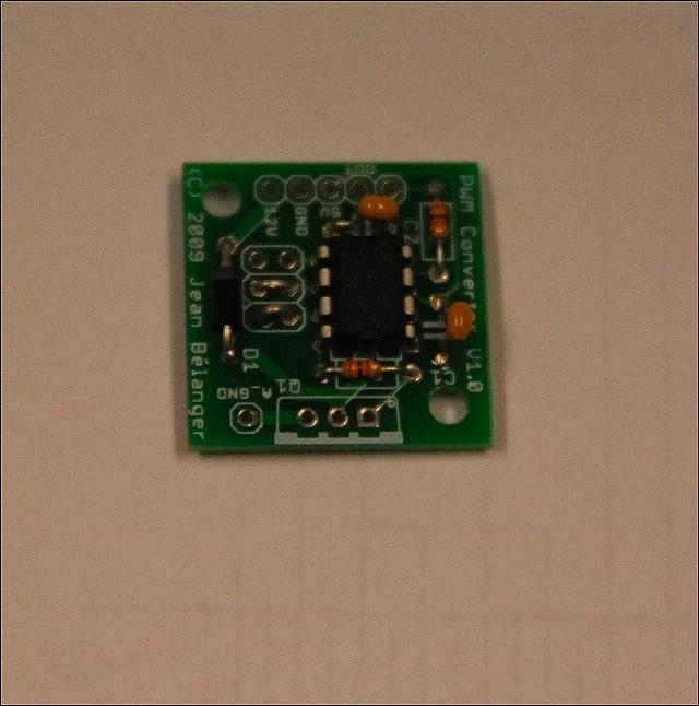
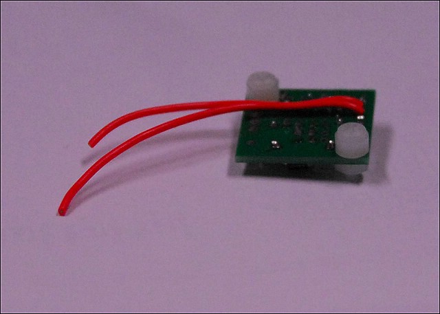
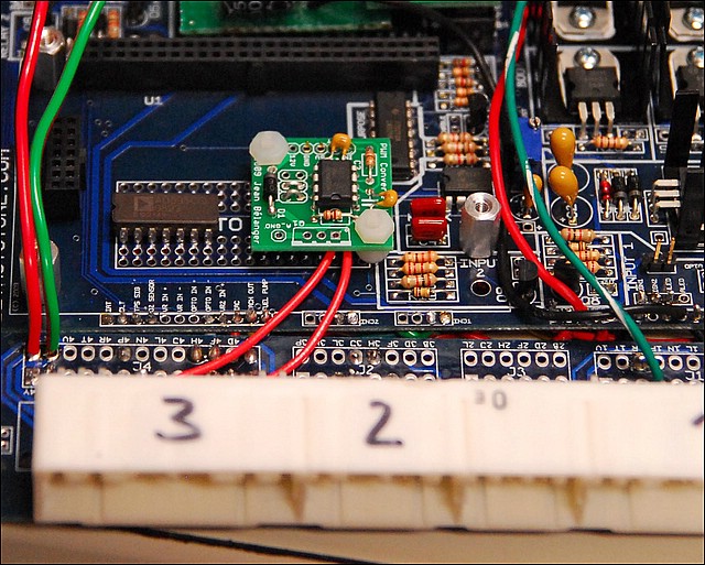
here is the PWM board:
I want to place the board under the Microsquirt module and want to use the
5V and ground which are already there - so I attach the 2 pin header which I have left over of my DIYPNP build in one 5V and one ground connector.
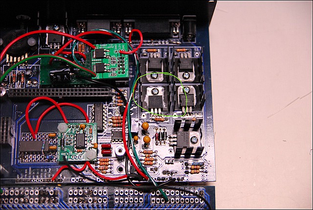
Now I took the plastik screws which are delivered with the PWM board and one of the plastic washers and put them in from the underside of the board as a spacer and fastened them.
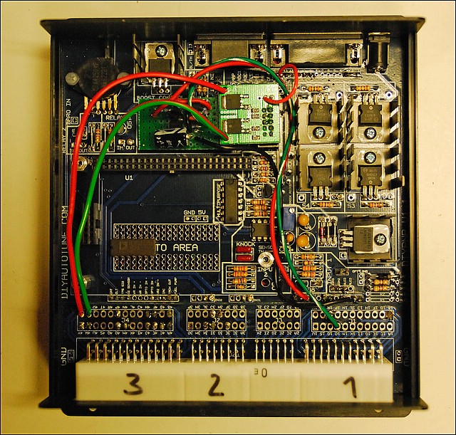
The board will be sitting like this:
2. The connections
I put all the informations I got in this spot - so it maybe double in the thread.
Now - how to connect.
MarcD's nice writeup isn't really usable for the DIYPNP. So I will have to find out how to connect this correctly.
Is asked Matt at DIYautotune and Jean about this.
--------------------------------------------------
Matt gave me the following advices:
[Q] - How do I have to connect the PWM board inside the DIYPNP?
- To use Jean's board, wire the IAC connection on the DIYPNP main board to In on Jean's board, and add a 1K 5 volt pull up on the IAC resistor in the pull ups area. That should do it. Note that this inverts the signal, so 100% duty cycle would be fully closed instead of fully open.
[Q] - And where does out go - [ ]
]
- Out goes to the valve, and the other connections wire to the matching points on the main board (12V, 5V, ground).
[Q] - so I have to remove the FB-diode which I have in the IAC pull-up?
-Yes, the resistor replaces the diode since it's now being used for a logic level signal to the PWM converter board.
--------------------------------------------------
Jean wrote:
Since I have not seen a DIYPNP board, it's a bit difficult to be certain about this so you might want to ask Marc D on that forum or the people from DIYAutotune. But basically, the board should installed in place of the TIP120 for the idle valve (assuming that this is the one function would want to use).
The IN pad on the PWM Converter board corresponds to the pin 1 on the TIP120, the OUT pad corresponds to pin 2 of the TIP120 and the A_GND pad corresponds to pin 3 of the TIP120. Then you need to wire the 5V and GND pads to the proto area 5V and ground and 12V to a 12V pad on the DIYPNP board. If there is already a diode on the DIYPNP board for the idle valve then you don't need to use the one on the PWM Converter board and you also don't need to have the wire for the 12V.
--------------------------------------------------
O.K. here is some more information:
Jean worte me a mail yesterday:
From what Matt says and from the DIYPNP doc, what you need to do is to have a 1K 5V pull up in the R5 spot on the DIYPNP board. Then you connect IN and OUT as Matt mentions: IN to the IAC pad and OUT to the valve (do you have a connector pin for that?). You will need to connect 5V, GND, 12V, A_GND to the appropriate places on the DIYPNP board and you will need to have the diode and TIP122 on the PWM converter board.
This is different from Marc D setup so don't do what he mentions because it won't work in your case. So you should have all the components on the PWM converter board and wires to all the pads (IN,OUT,5V,GND,12V,A_GND).
By the way, it's best to wire A_GND as close to the DIYPNP board connector as possible since this potentially has some noise on it. So if there is a ground connection on the connector board, use it. The GND pad should be connected to the proto area ground.
My problem now was - I would have no possibility to connect the TIP122 to the case.
Jean answered:
You will have to check if it gets warm. If it does then you'll need to find another spot where you can heat sink it.
You could always mount the TIP122 remotely: mount it to the case and run wires to the PWM board. In that case you could run a wire directly from pin 2 to the valve instead of using OUT.
So I connected as follows:
- 5V - proto area DIYPNP (using 2-pin header)
- ground - proto area DIYPNP (using 2-pin header)
- in - IAC
- out - n.c.
- TIP122 pin 2 - 4O (at my DIYPNP with +12V at 4M or just the other way round) equals OUT at PWM board
- 12V - to a 12V source at the edge
- a_ground - to a ground spot at the connector board as recommended by Jean (due to noise)
- 1K pull-up - to +5V at pull-up area (IAC)
3. the assembly
First I removed the flyback diode from the pull-up area and put a 1K pull-up resistor to +5V in.
As I am short of outputs anyway and don't need the BIPs for spark 3&4 - I removed the BIP from S4.
I screwed the TIP122 on the heatsink and bent the Pins upwards - do not connect to the soldering points of S4.
Now I wired pin 1 and pin 3 of the TIP122 to the soldering points at the PWM board and pin 2 to the valve connector
(4O or 4M - whether you have applied +12V to 4M or 4O)
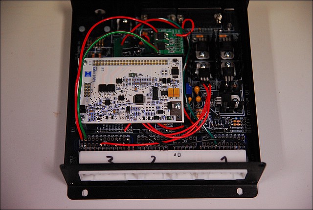
Put the microsquirt board back on:
5. Software change:
I set the factor at the PWM idle settings to 1.
This should be it.
Greets
I just received my PWM converter board and would like to document how I will attach it to the DIYPNP.
1. The placement:
Here is a pic of the DIYPNP without the Microsquirt module:
here is the PWM board:
I want to place the board under the Microsquirt module and want to use the
5V and ground which are already there - so I attach the 2 pin header which I have left over of my DIYPNP build in one 5V and one ground connector.
Now I took the plastik screws which are delivered with the PWM board and one of the plastic washers and put them in from the underside of the board as a spacer and fastened them.
The board will be sitting like this:
2. The connections
I put all the informations I got in this spot - so it maybe double in the thread.
Now - how to connect.
MarcD's nice writeup isn't really usable for the DIYPNP. So I will have to find out how to connect this correctly.
Is asked Matt at DIYautotune and Jean about this.
--------------------------------------------------
Matt gave me the following advices:
[Q] - How do I have to connect the PWM board inside the DIYPNP?
- To use Jean's board, wire the IAC connection on the DIYPNP main board to In on Jean's board, and add a 1K 5 volt pull up on the IAC resistor in the pull ups area. That should do it. Note that this inverts the signal, so 100% duty cycle would be fully closed instead of fully open.
[Q] - And where does out go - [
]- Out goes to the valve, and the other connections wire to the matching points on the main board (12V, 5V, ground).
[Q] - so I have to remove the FB-diode which I have in the IAC pull-up?
-Yes, the resistor replaces the diode since it's now being used for a logic level signal to the PWM converter board.
--------------------------------------------------
Jean wrote:
Since I have not seen a DIYPNP board, it's a bit difficult to be certain about this so you might want to ask Marc D on that forum or the people from DIYAutotune. But basically, the board should installed in place of the TIP120 for the idle valve (assuming that this is the one function would want to use).
The IN pad on the PWM Converter board corresponds to the pin 1 on the TIP120, the OUT pad corresponds to pin 2 of the TIP120 and the A_GND pad corresponds to pin 3 of the TIP120. Then you need to wire the 5V and GND pads to the proto area 5V and ground and 12V to a 12V pad on the DIYPNP board. If there is already a diode on the DIYPNP board for the idle valve then you don't need to use the one on the PWM Converter board and you also don't need to have the wire for the 12V.
--------------------------------------------------
O.K. here is some more information:
Jean worte me a mail yesterday:
From what Matt says and from the DIYPNP doc, what you need to do is to have a 1K 5V pull up in the R5 spot on the DIYPNP board. Then you connect IN and OUT as Matt mentions: IN to the IAC pad and OUT to the valve (do you have a connector pin for that?). You will need to connect 5V, GND, 12V, A_GND to the appropriate places on the DIYPNP board and you will need to have the diode and TIP122 on the PWM converter board.
This is different from Marc D setup so don't do what he mentions because it won't work in your case. So you should have all the components on the PWM converter board and wires to all the pads (IN,OUT,5V,GND,12V,A_GND).
By the way, it's best to wire A_GND as close to the DIYPNP board connector as possible since this potentially has some noise on it. So if there is a ground connection on the connector board, use it. The GND pad should be connected to the proto area ground.
My problem now was - I would have no possibility to connect the TIP122 to the case.
Jean answered:
You will have to check if it gets warm. If it does then you'll need to find another spot where you can heat sink it.
You could always mount the TIP122 remotely: mount it to the case and run wires to the PWM board. In that case you could run a wire directly from pin 2 to the valve instead of using OUT.
So I connected as follows:
- 5V - proto area DIYPNP (using 2-pin header)
- ground - proto area DIYPNP (using 2-pin header)
- in - IAC
- out - n.c.
- TIP122 pin 2 - 4O (at my DIYPNP with +12V at 4M or just the other way round) equals OUT at PWM board
- 12V - to a 12V source at the edge
- a_ground - to a ground spot at the connector board as recommended by Jean (due to noise)
- 1K pull-up - to +5V at pull-up area (IAC)
3. the assembly
First I removed the flyback diode from the pull-up area and put a 1K pull-up resistor to +5V in.
As I am short of outputs anyway and don't need the BIPs for spark 3&4 - I removed the BIP from S4.
I screwed the TIP122 on the heatsink and bent the Pins upwards - do not connect to the soldering points of S4.
Now I wired pin 1 and pin 3 of the TIP122 to the soldering points at the PWM board and pin 2 to the valve connector
(4O or 4M - whether you have applied +12V to 4M or 4O)
Put the microsquirt board back on:
5. Software change:
I set the factor at the PWM idle settings to 1.
This should be it.
Greets
Last edited by Zaphod; 11-11-2009 at 10:07 AM.

Reply
 0
0

0
11-07-2009, 05:40 AM
#2

Matt gave me the following advices:
[Q] - How do I have to connect the PWM board inside the DIYPNP?
- To use Jean's board, wire the IAC connection on the DIYPNP main board to In on Jean's board, and add a 1K 5 volt pull up on the IAC resistor in the pull ups area. That should do it. Note that this inverts the signal, so 100% duty cycle would be fully closed instead of fully open.
[Q] - And where does out go - [
]- Out goes to the valve, and the other connections wire to the matching points on the main board (12V, 5V, ground).
[Q] - so I have to remove the FB-diode which I have in the IAC pull-up?
-Yes, the resistor replaces the diode since it's now being used for a logic level signal to the PWM converter board.
--------------------------------------------------
Jean wrote:
Since I have not seen a DIYPNP board, it's a bit difficult to be certain about this so you might want to ask Marc D on that forum or the people from DIYAutotune. But basically, the board should installed in place of the TIP120 for the idle valve (assuming that this is the one function would want to use).
The IN pad on the PWM Converter board corresponds to the pin 1 on the TIP120, the OUT pad corresponds to pin 2 of the TIP120 and the A_GND pad corresponds to pin 3 of the TIP120. Then you need to wire the 5V and GND pads to the proto area 5V and ground and 12V to a 12V pad on the DIYPNP board. If there is already a diode on the DIYPNP board for the idle valve then you don't need to use the one on the PWM Converter board and you also don't need to have the wire for the 12V.
--------------------------------------------------
Now I still got some questions:
- Do I need the TIP120 at Jeans board - I think this is still in the DIYPNP - and if so do I need to connect the 12V anyway? Would I have to put a jumper in as MarcD did on his PWM board, where the TIP belongs?
So at the moment I would connect as follows:
- 5V - proto area DIYPNP
- ground - proto area DIYPNP
- in - IAC
- out - 4O (at my DIYPNP with +12V at 4M or just the other way round
- 12V - ? needed?
- a_ground - ? needed?
Thanks for your input on my leftover questions - I am going to document the rest of the build as it goes along...
Greets
The IN goes to the idle output from the ECU. The OUT goes to the TIP, which goes out to the valve.
Reply
0
0
11-07-2009, 08:26 AM
#3
Senior Member

Join Date: Nov 2007
Location: Belgium
Posts: 999
Total Cats: 73
the TIP120 does not need 12V.
The 12V on Jean's board is only there for the flyback diode. That diode goes between 12V and the middle pin of the TIP120. If the diode is already somewhere else (in the DIYPNP or directly over the valve), you don't need the diode nor the 12V.
The 12V on Jean's board is only there for the flyback diode. That diode goes between 12V and the middle pin of the TIP120. If the diode is already somewhere else (in the DIYPNP or directly over the valve), you don't need the diode nor the 12V.
Reply
0
0
11-07-2009, 11:13 AM
#4
Elite Member
Thread Starter
Join Date: Mar 2006
Location: Schwarzenberg, Germany
Posts: 1,553
Total Cats: 101
I don't know and didn't find anything about the pwm idle circuit at the DIYPNP. The DIYPNP page doesn't mention this anywhere...
Maybe Matt or Jerry can chime in on this.
Greets
Maybe Matt or Jerry can chime in on this.
Greets
Reply
0
0
11-08-2009, 04:00 AM
#5
Elite Member
Thread Starter
Join Date: Mar 2006
Location: Schwarzenberg, Germany
Posts: 1,553
Total Cats: 101
O.K. here is some more information:
Jean worte me a mail yesterday:
From what Matt says and from the DIYPNP doc, what you need to do is to have a 1K 5V pull up in the R5 spot on the DIYPNP board. Then you connect IN and OUT as Matt mentions: IN to the IAC pad and OUT to the valve (do you have a connector pin for that?). You will need to connect 5V, GND, 12V, A_GND to the appropriate places on the DIYPNP board and you will need to have the diode and TIP122 on the PWM converter board.
This is different from Marc D setup so don't do what he mentions because it won't work in your case. So you should have all the components on the PWM converter board and wires to all the pads (IN,OUT,5V,GND,12V,A_GND).
By the way, it's best to wire A_GND as close to the DIYPNP board connector as possible since this potentially has some noise on it. So if there is a ground connection on the connector board, use it. The GND pad should be connected to the proto area ground.
My problem now was - I would have no possibility to connect the TIP122 to the case.
Jean answered:
You will have to check if it gets warm. If it does then you'll need to find another spot where you can heat sink it.
You could always mount the TIP122 remotely: mount it to the case and run wires to the PWM board. In that case you could run a wire directly from pin 2 to the valve instead of using OUT.
Now I think - if the BIPs are unnecessary anyway - couldn't I use one of the heatsinks (or even one of the mounting points - to mount/connect the TIP122?
Thanks
Sven
Reply
0
0
 04-06-2010, 02:29 PM
#8
Elite Member
Thread Starter
Join Date: Mar 2006
Location: Schwarzenberg, Germany
Posts: 1,553
Total Cats: 101
Hi at all,
today I had the opportunity to get my car up and running a bit.
I already noticed with the last 2 or 3 attempts after the winter that my car starts o.k. and stalls immediately if I didn't blip the throttle and idles at very low revs even at low temps.
I pulled the IAC plug when the car was warmed up and absolutely nothing happend - the same with the idle valve test - nothing.
So I have to do some troubleshooting for my PWM converter board - maybe someone has an idea?
I didn't put the middle pin of the TIP122 back to the board but directly to the 4M pin to the IAC - (someone suggested I could do this maybe I have to route it via the PWM board?
Greets
Reply
0
0
04-06-2010, 09:27 PM
#10
Newb

Join Date: Feb 2010
Posts: 35
Total Cats: 0
You need to check what the input signal looks like and if you get an output signal out of the board CPU.
If you have an oscilloscope then it's easy: just scope the input and output (pins 1 and 8, respectively). If you don't have a scope, you could use a voltmeter: 0% duty cycle should give you 0V, 100% duty cycle should give you 5V, and anything in between should give you a voltage in between these proportional to the duty cycle. And the cheaper the voltmeter, the better.
You should have the same voltage at pins 1 and 8 since the duty cycle is not changed but only the frequency. And also check that you have 5V at the CPU on pin 3 and 0V on pin 4.
Jean
Reply
0
0
04-07-2010, 01:56 AM
#11
Elite Member
Thread Starter
Join Date: Mar 2006
Location: Schwarzenberg, Germany
Posts: 1,553
Total Cats: 101
Thanks Jean, I am going to test this out...
Something is definitly wrong
I just did a test, I get 10.6 V between IN and +12V... and like 0.37V between OUT and +12V. (shown DC is 65.2%) - WTF?
All the input voltages to the board +5V, +12V and ground are correct.
I can't reach the Pins of the CPU with the Microsquirt attached, but without the Microsquirt I get like 7.X V at Pin 3...
Wait - I just had a look at your homepage:
"The board has been tested on the MegaSquirt FIDLE and JS11 outputs with the FIDLE signal and the boost control signal. The board needs a 5V input signal and cannot take a 12V input signal so it cannot take one of the IAC outputs as its input. What could be done is using a voltage divider (2 resistors) to reduce the voltage. One thing that needs to be verified is if the UDN2916 can be fed with 5V instead of 12V (on JS9) which would make this an easy way to have a 5V signal."
Maybe this is my problem?
Greets
Last edited by Zaphod; 04-07-2010 at 03:11 AM.
Reply
0
0
04-07-2010, 03:24 AM
#12
Elite Member

iTrader: (10)
Join Date: Jun 2006
Location: Athens, Greece
Posts: 5,976
Total Cats: 355
If you have the IN pad connected to the IDLE Out pin on the Microsquirt module board, it should work fine. Alternatively, you can connect it to IAC pad on the mainboard.
Jim
Jim
Reply
0
0
04-07-2010, 04:08 AM
#13
Elite Member
Thread Starter
Join Date: Mar 2006
Location: Schwarzenberg, Germany
Posts: 1,553
Total Cats: 101
I have it connected to IAC at the mainboard, but pin 20 (idle out) at the Microsquirt module also gives me 10.6V... 
Edit: Maybe we got a suspected... I removed the 5V pull-up to the IAC and get much more reasonable voltages...
Gonna test in the car soon.
2nd edit:
Nothing to do with the Pull-up.
I can't get that bloody IAC valve to do anything.
Edit: Maybe we got a suspected... I removed the 5V pull-up to the IAC and get much more reasonable voltages...
Gonna test in the car soon.
2nd edit:
Nothing to do with the Pull-up.
I can't get that bloody IAC valve to do anything.
Last edited by Zaphod; 04-07-2010 at 07:26 AM.
Reply
0
0
04-07-2010, 10:18 AM
#14
Newb
Join Date: Feb 2010
Posts: 35
Total Cats: 0
Why are you measuring between the IN/OUT and 12V? You need to measure between IN/OUT and ground. And your pullup for the IAC is hopefully a 5V pullup. If it's a 12V then the CPU is toast.
And the quote you mention is not for the DIYPNP because the Microsquirt module doesn't use the UDN2916.
So make sure you can get the correct voltage at the input which should correspond to the duty cycle times 5V (or maybe the inverse of the duty cycle in this case). If you can't get that then there is an issue somewhere else. If you can get it then look at the output.
Jean
Reply
0
0
04-07-2010, 11:41 AM
#15
Elite Member
Thread Starter
Join Date: Mar 2006
Location: Schwarzenberg, Germany
Posts: 1,553
Total Cats: 101
Sorry for the mistake with the +12V...
First of all - the pullup is a 5V and was all the time.
Now I just did a quick test on the bench again.
IN is measuring 1.90V with 60.2% Idle PWM.
OUT is measuring 0.18V...
With the idle valve test at 80%
IN 0.95V
OUT 0.09V
at 20%
IN 3.86V
OUT 0.41V
OUT seems to be always something like 10 times lower than IN...
Where could the problem be?
The CPU toast?
Thanks
Reply
0
0
04-07-2010, 11:57 AM
#16
Newb
Join Date: Feb 2010
Posts: 35
Total Cats: 0
The input is correct and I suspect the output also but you need to measure pin 8 on the CPU to be certain. If you measure elsewhere, the measurement will depend on the state of the other components.
So check the output at pin 8 of the CPU. Then check pin 2 on the TIP122. This last one should have a voltage equal to the duty cycle times 12V (and not the reverse of the duty cycle like you're seeing on the input since the TIP122 will invert the signal).
Jean
So check the output at pin 8 of the CPU. Then check pin 2 on the TIP122. This last one should have a voltage equal to the duty cycle times 12V (and not the reverse of the duty cycle like you're seeing on the input since the TIP122 will invert the signal).
Jean
Reply
0
0
04-07-2010, 01:37 PM
#17
Elite Member
Thread Starter
Join Date: Mar 2006
Location: Schwarzenberg, Germany
Posts: 1,553
Total Cats: 101
I just rewired everything just to get to the PINs with the Microsquirt attached...
Which one is Pin 8 at the CPU?
I get in this order
With a dutycycle of 60%
IN 1.90 V
OUT 0.19 V
Pin 2 of TIP122 0.19V
PINs at the CPU
I try to show the little mark on the CPU here
-v-
2.01 1.84
4.84 0.00
4.97 0.00
0.00 4.84
Does this help?
Thanks again..
Which one is Pin 8 at the CPU?
I get in this order
With a dutycycle of 60%
IN 1.90 V
OUT 0.19 V
Pin 2 of TIP122 0.19V
PINs at the CPU
I try to show the little mark on the CPU here
-v-
2.01 1.84
4.84 0.00
4.97 0.00
0.00 4.84
Does this help?
Thanks again..
Last edited by Zaphod; 04-07-2010 at 01:51 PM.
Reply
0
0
04-07-2010, 01:52 PM
#19
Newb
Join Date: Feb 2010
Posts: 35
Total Cats: 0
The pins where you got 2.01 and 1.84 are pins 1 and 8. So as you can see you do get essentially the same voltage. The difference comes from using a voltmeter and different frequencies.
So the CPU is fine. The issue is the TIP122 and/or the way you have it connected. You need to make sure you have the valve connected to 12V and to pin 2 of the TIP122. Pin 3 of the TIP122 needs to be connected to ground and you need a diode between pin 2 of the TIP122 and 12V.
If the connections are ok then the TIP122 may have failed for some reason. You could also use a LED tester in place of the valve to see if it lights up with a varying brightness depending on duty cycle.
Jean
Reply
0
0
04-07-2010, 02:24 PM
#20
Elite Member
Thread Starter
Join Date: Mar 2006
Location: Schwarzenberg, Germany
Posts: 1,553
Total Cats: 101
O.K.
so - lets track this down
1. the valve is connected to +12 V (via 4M on the connector board)
2. the valve is connected to PIN 2 of the TIP122 (via 4O on the connector board)
3. PIN 3 is connected to ground
4. the diode is on your board between +12V and PIN2
So I guess the TIP122 is gone - I get a new one and see what happens...
Reply
0
0


