MegaSquirt Ignition Issues
 01-03-2008, 11:28 PM
#1
Junior Member
Thread Starter

Join Date: Oct 2007
Location: AC, NJ
Posts: 345
Total Cats: 0
I am not getting spark on coil pack 1.
When I boot the MS up, one LED turns on immediately and the other lags behind (D16), then they both get brighter because I have it set to ignition hold 1. I figure they are both supposed to light up at the same time.
The one that isn't firing eventually lights up, but it takes a second.
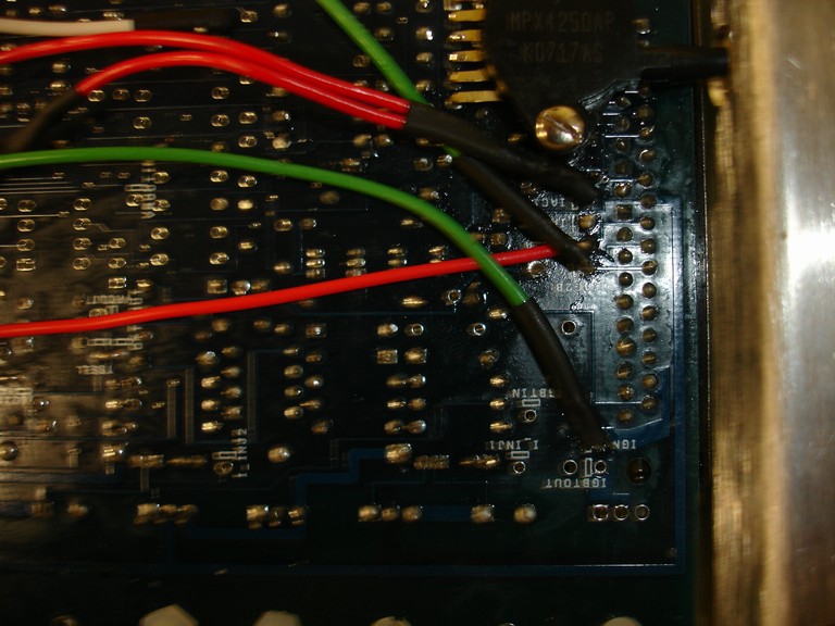
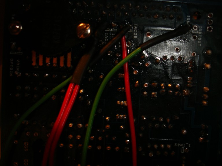
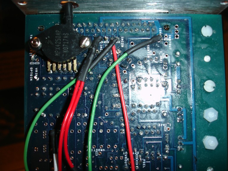
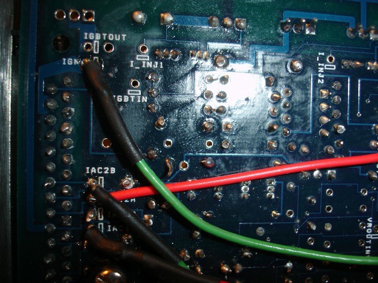
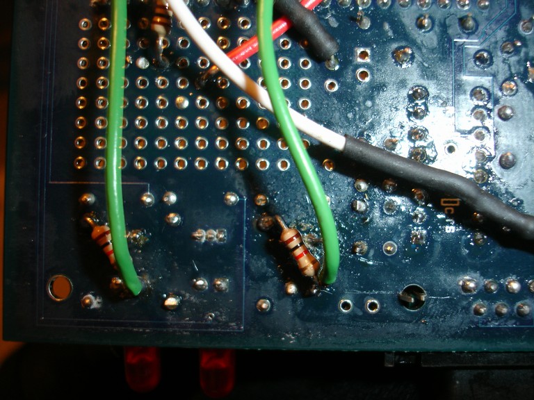
The D14 circuit contains R24, D14, R26, and Q6. It also takes an input from the processor, so technically the CPU is part of the processor too.
I swapped processors, tested both resistors, and replaced the transistor with same result.
Any suggestions?
http://www.megamanual.com/ms2/v3pcb_7.gif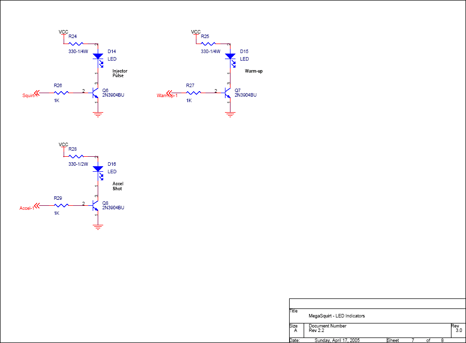
When I boot the MS up, one LED turns on immediately and the other lags behind (D16), then they both get brighter because I have it set to ignition hold 1. I figure they are both supposed to light up at the same time.
The one that isn't firing eventually lights up, but it takes a second.
The D14 circuit contains R24, D14, R26, and Q6. It also takes an input from the processor, so technically the CPU is part of the processor too.
I swapped processors, tested both resistors, and replaced the transistor with same result.
Any suggestions?
http://www.megamanual.com/ms2/v3pcb_7.gif
Last edited by compy; 01-04-2008 at 12:59 PM.

Reply
 0
0

0
01-03-2008, 11:34 PM
#3
Junior Member
Thread Starter
Join Date: Oct 2007
Location: AC, NJ
Posts: 345
Total Cats: 0
that was quick..
I know the inputs are correct (tach worked fine), so its something with the outputs...
I'm pretty sure the wires and resistors are correct.
I know the inputs are correct (tach worked fine), so its something with the outputs...
I'm pretty sure the wires and resistors are correct.
Last edited by compy; 01-03-2008 at 11:49 PM.
Reply
0
0
 01-04-2008, 12:28 AM
#7
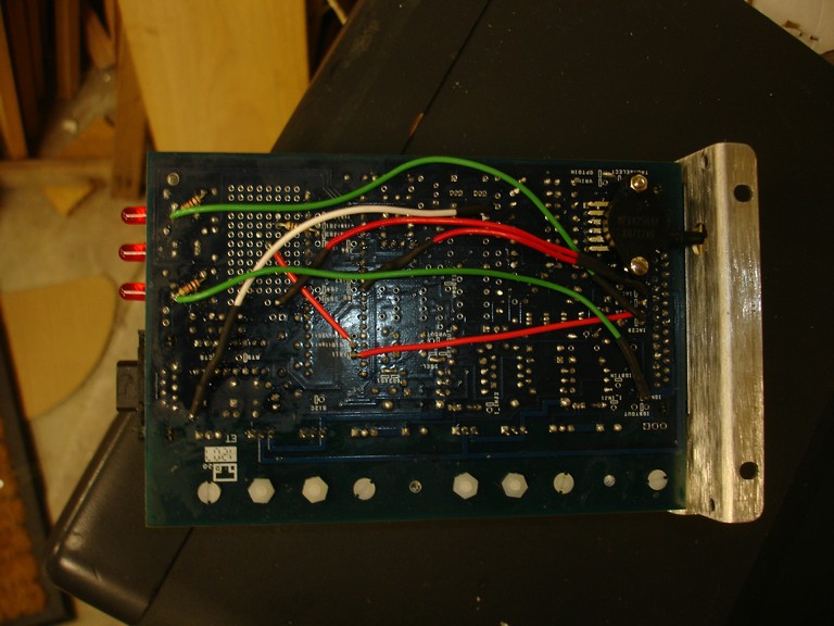
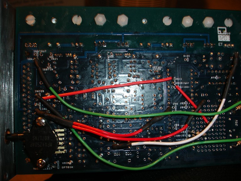
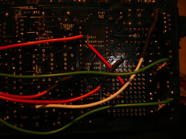
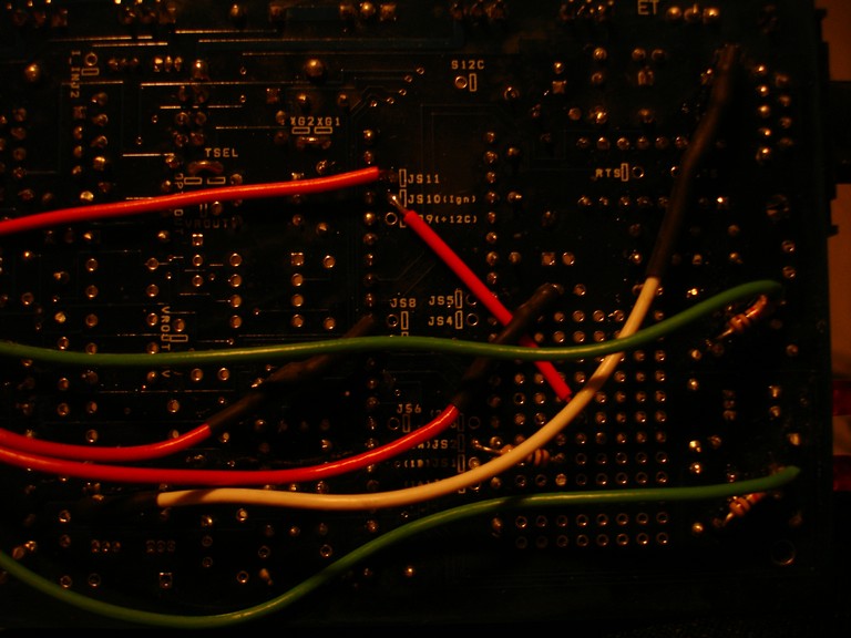
I flashed it with 029v before i sent it back to him. It ran my car on one cylinder. I had no scope though so i couldn't check the outputs on the D14 circuit. So i tried my own processor in it. Swapped in a new transistor. Double checked everything on the bottom in terms of spark mods. It gets a good solid Tach reading without problems.
With a STIM connected both LEDs light equally as fast as each other without problems. With my coils disconnected both LEDs would light at exactly the same time. Switching my coils around, thinking that the coil itself might be the issue didn't change anything. D14 still lags behind D16.
With a STIM connected both LEDs light equally as fast as each other without problems. With my coils disconnected both LEDs would light at exactly the same time. Switching my coils around, thinking that the coil itself might be the issue didn't change anything. D14 still lags behind D16.
Reply
0
0
01-04-2008, 11:34 AM
#9
Boost Czar


iTrader: (62)
Join Date: May 2005
Location: Chantilly, VA
Posts: 79,488
Total Cats: 4,077
maybe the 5v voltage regulator is bad. U5, IIRC 
or the transistors are messed up, otherwise the circuit goes through a few resistors and the CPU itself. If Chad tried his CPU and it did the same, then that's ruled out.
or i guess U5 is good since the one fires.....maybe F1 or F2 is bad?
or the transistors are messed up, otherwise the circuit goes through a few resistors and the CPU itself. If Chad tried his CPU and it did the same, then that's ruled out.
or i guess U5 is good since the one fires.....maybe F1 or F2 is bad?
Reply
0
0
01-04-2008, 01:06 PM
#10
Junior Member
Thread Starter
Join Date: Oct 2007
Location: AC, NJ
Posts: 345
Total Cats: 0
Install and solder F1 and F2 {RXEF050-ND}. These are � Amp poly fuses (small yellow discs that look similar to some capacitors) that acts like a circuit breaker on the 5 Volt supply to the PCB from the regulator. F1 installs very near the DB9, in the middle of some of the capacitors you have already installed. F2 installs near the center of the DB37 connector, and very close to it.
F1, F2 RXEF050-ND 0.48 Spares Polyswitch RXE Series 0.50A HOLD
They do not physically look like there is anything wrong with it. How do you go about testing one?
F1, F2 RXEF050-ND 0.48 Spares Polyswitch RXE Series 0.50A HOLD
They do not physically look like there is anything wrong with it. How do you go about testing one?
Reply
0
0
01-04-2008, 08:39 PM
#11
Elite Member
iTrader: (21)
Join Date: Jun 2006
Location: Point Pleasant, NJ
Posts: 2,957
Total Cats: 2
good luck with answers Jason now that you went and got yourself banned. haha. i wish i had a ban stick in real life. does this mean i can ban you from borrowing my MS from Chad?
Reply
0
0


Thread
Thread Starter
Forum
Replies
Last Post
Zaphod
MEGAsquirt
47
10-26-2018 11:00 PM


