Yank's brick with MS3X (Noob tuner FTL)
 01-02-2012, 05:49 PM
#21

Is anyone running launch control with MS? Im wondering how you have it set up and what the logic is in your setup. The diagram i have says to use a momentary switch. is that the clutch pedal or a push button in the dash? Ive also seen the guy on youtube that runs an on/off switch for launch. does this mean he has to turn the switch off to have his normal rev limit after he dumps the clutch or does the VSS tell the ecu that its moving and to raise the limit even with the switch on?

Reply
 0
0

0
01-02-2012, 06:01 PM
#22
Boost Czar


iTrader: (62)
Join Date: May 2005
Location: Chantilly, VA
Posts: 79,493
Total Cats: 4,080
yes. I just use TPS and the clutch switch.
Its better with the VSS hooked up. the on/off switch helps make sure it doesn't activate when driving and shifting, but the vss filter solves that.
Its better with the VSS hooked up. the on/off switch helps make sure it doesn't activate when driving and shifting, but the vss filter solves that.
Reply
0
0
01-03-2012, 11:47 AM
#23
So im going to refer to this for VSS.
https://www.miataturbo.net/showthrea...&highlight=vss
and Ill do this for the launch control circuit. (See attached)
Reply
0
0
01-03-2012, 11:52 AM
#24
Boost Czar
iTrader: (62)
Join Date: May 2005
Location: Chantilly, VA
Posts: 79,493
Total Cats: 4,080
perfect. but I dont think you really need the override switch once the VSS filter is in place...unless you really want to rev your throttle to impress the ladies at stoplights.
fwiw, launch and vss have spots ready to go in the ms3x board without building anything.
fwiw, launch and vss have spots ready to go in the ms3x board without building anything.
Reply
0
0
01-03-2012, 12:16 PM
#25
I knew there was something for launch but i wasnt for sure on the vss. from what i've seen so far i'd need to use one of the 4 data inputs and the only one i have left is the nitrous switch. I read somewhere there is an output on the back of the gauge cluster on '90 miatas that isnt used and can tie into the ms3. Ill look more into this.
Reply
0
0
01-05-2012, 10:47 PM
#27
Okay I think im all read up on the VSS signal. This is what i've come up with. Ive referenced a few threads that said tapping into the RSW signal didnt work but they never mentioned building in the 5V pull up.
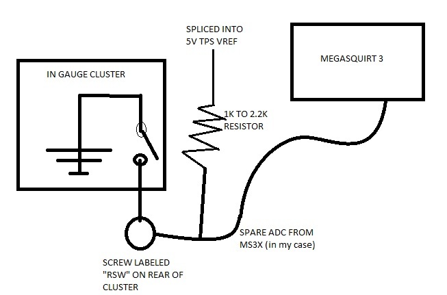
Does anyone foresee any issues with me using the TPS VREF 5V signal for the Cam position sensor, VSS source pull up, and the TPS source?
I've been doing alot of reading and im learning alot here guys. Thanks for the help!
Does anyone foresee any issues with me using the TPS VREF 5V signal for the Cam position sensor, VSS source pull up, and the TPS source?
I've been doing alot of reading and im learning alot here guys. Thanks for the help!
Reply
0
0
01-06-2012, 11:37 AM
#28
Senior Member

Join Date: Aug 2010
Location: Maumelle, AR
Posts: 613
Total Cats: 3
If you use the ms3x inputs you don't have to put a pull up on the line... There already is one on those inputs (check the ms3x schematic if you don't believe me, nitrous 1 doesn't have the pullup by default, but can be jumpered on the ms3x board to have one). I'm using the VSS signal from the gauge cluster, it comes out right at the harness and is soldered straight onto a ms3x input pin.
edit: Also, I think in general 1-2.2k is a little low for a pull up, think 4.7k or higher. moot point but anyway
edit: Also, I think in general 1-2.2k is a little low for a pull up, think 4.7k or higher. moot point but anyway
Reply
0
0
01-06-2012, 12:30 PM
#30
mkturbo.com
iTrader: (24)
Join Date: May 2006
Location: Charleston SC
Posts: 15,177
Total Cats: 1,681
If you use the ms3x inputs you don't have to put a pull up on the line... There already is one on those inputs (check the ms3x schematic if you don't believe me, nitrous 1 doesn't have the pullup by default, but can be jumpered on the ms3x board to have one). I'm using the VSS signal from the gauge cluster, it comes out right at the harness and is soldered straight onto a ms3x input pin.
edit: Also, I think in general 1-2.2k is a little low for a pull up, think 4.7k or higher. moot point but anyway
edit: Also, I think in general 1-2.2k is a little low for a pull up, think 4.7k or higher. moot point but anyway
Reply
0
0
01-06-2012, 12:45 PM
#32
see attached.
"R65,R66,R67 are optional 'bias' resistors on the analogue inputs EXT_MAP, EGO2, SPARE_ADC respectively. These would be typically used when connecting a resistive temperature sensor to one of the inputs. For standard calibration, use a 2.49K resistor with a GM style coolant or air temperature sensor."
source: http://www.msextra.com/doc/ms3/hardware.html
Reply
0
0
01-06-2012, 05:52 PM
#36
Ben Berusch of DIY autotune responding to the use of SPARE ADC.=
"There are about a dozen different pins you can use for the launch input. I don't know if it needs external pullup or not. Try it, and if it doesn't work, then add a pullup."
frustrating...
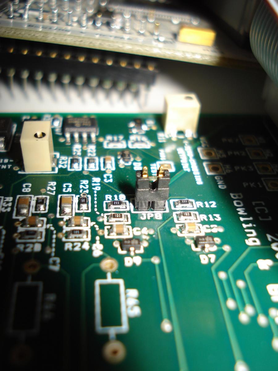
I opened the case to see whats up and this is what i have..
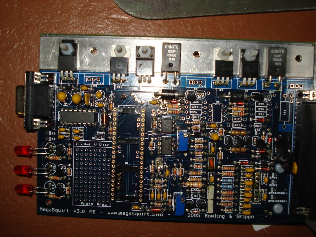
Maybe i should just listen to Braineack from the get go..
Brain, did you mean JS8 to the JS9/S12C node?
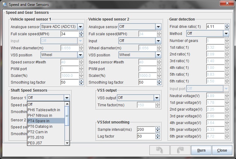
I need to use the shaft speed settings then and leave the vehicle speed sensor settings set to off. (that's where i was thinking i could use spare adc)
Unrelated Q:
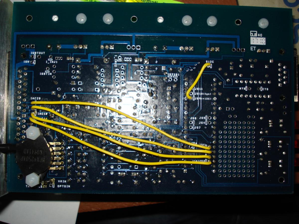
Also take a look at the bottom of the board. I used jumpers from Tach select and VRIN and VROUT (seen center and next to MAP sensor.) Im using a ford hall effect sensor (cam angle sensor 2 wire) as my crank angle sensor to watch missing tooth. I built this under the impression that i was going to use a VR sensor but ended up with the hall instead.
"There are about a dozen different pins you can use for the launch input. I don't know if it needs external pullup or not. Try it, and if it doesn't work, then add a pullup."
frustrating...
I opened the case to see whats up and this is what i have..
Brain, did you mean JS8 to the JS9/S12C node?
I need to use the shaft speed settings then and leave the vehicle speed sensor settings set to off. (that's where i was thinking i could use spare adc)
Unrelated Q:
Also take a look at the bottom of the board. I used jumpers from Tach select and VRIN and VROUT (seen center and next to MAP sensor.) Im using a ford hall effect sensor (cam angle sensor 2 wire) as my crank angle sensor to watch missing tooth. I built this under the impression that i was going to use a VR sensor but ended up with the hall instead.
Reply
0
0
01-06-2012, 06:53 PM
#39
aah My bad i thought you were talking about modding the main board. Looks to me like there already is a jumper on mine.
This mean i should disregard this?
and just hook up the NITROUS IN to RSW?
FYI i also have the same jumper in JP3 (Tacho output pullup (not using)), and JP7 (Cam input pullup (using currently with 3 wire CAS 1 ground, 1 5V source from TPS VREF and signal to ecu via CAM INPUT wire.))
This mean i should disregard this?
FYI i also have the same jumper in JP3 (Tacho output pullup (not using)), and JP7 (Cam input pullup (using currently with 3 wire CAS 1 ground, 1 5V source from TPS VREF and signal to ecu via CAM INPUT wire.))
Reply
0
0


