MS2e Knock sensor wiring and EBC pin out testing
 06-10-2016, 01:46 AM
#1
Junior Member

Thread Starter
iTrader: (6)
Join Date: Mar 2010
Location: Morgan Hill, CA
Posts: 382
Total Cats: 27
I'm trying to finish up my MS Labs MS2e install and there are a couple of items that are missing documentation:
1) What is the wiring for the knock sensor? White goes to "+" but which of the 2 wires is that coming from the sensor?
Where do you connect the other wire (is it to ground or 12v or 5v)?
2) How can we test ECB with no load (bench test pin 20) to make sure it is fully operational?
1) What is the wiring for the knock sensor? White goes to "+" but which of the 2 wires is that coming from the sensor?
Where do you connect the other wire (is it to ground or 12v or 5v)?
2) How can we test ECB with no load (bench test pin 20) to make sure it is fully operational?

 0
0
 06-10-2016, 02:42 AM
#2
Elite Member
iTrader: (10)
Join Date: Jun 2006
Location: Athens, Greece
Posts: 5,976
Total Cats: 355
1) Knock sensors usually have 2 wires, one is the center/core, and the other is also the shielding. The center wire is the signal; the shielding should be grounded on the MS2, pin 3.
2) Ground the purple wire to switch to boost table 2, and put 50 in all the cells in the table. You should hear the solenoid clicking.
2) Ground the purple wire to switch to boost table 2, and put 50 in all the cells in the table. You should hear the solenoid clicking.
0
06-10-2016, 03:16 AM
#3
Junior Member
Thread Starter
iTrader: (6)
Join Date: Mar 2010
Location: Morgan Hill, CA
Posts: 382
Total Cats: 27
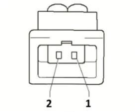
I have the Bocsh 0 261 231 006 sensor in a kit from FM you recommend and it has connector with two pins and FM supplied the corresponding connector with a two wire pigtail (Red & Orange). How would I go about determining which wire is the signal and which one goes to ground?
Last edited by Cxracer; 06-10-2016 at 09:49 AM.
0
 <br >
06-24-2016, 10:41 PM
<br >
06-24-2016, 10:41 PM
#5
Junior Member
Thread Starter
iTrader: (6)
Join Date: Mar 2010
Location: Morgan Hill, CA
Posts: 382
Total Cats: 27
According to the diagram and the corresponding Red and Orange wires in the FM pigtail, Red (+) should go to White and Orange (-) should go to Black/Green sensor ground.
Wired in and hopefully correct. Will test this weekend.
Wired in and hopefully correct. Will test this weekend.
0
07-01-2016, 11:45 PM
#6
Junior Member
Thread Starter
iTrader: (6)
Join Date: Mar 2010
Location: Morgan Hill, CA
Posts: 382
Total Cats: 27
It seems to be working properly with the signal show at about 3-4% on the TunerStudio gauge cluster.
I'll report if anything goes wrong but seems you can use this to verify the correct connection between the FM knock sensor kit and a Reverent MS2e
I'll report if anything goes wrong but seems you can use this to verify the correct connection between the FM knock sensor kit and a Reverent MS2e
0

Thread
Thread Starter
Forum
Replies
Last Post
beansrown
MEGAsquirt
2
04-02-2012 01:12 PM


