When you click on links to various merchants on this site and make a purchase, this can result in this site earning a commission. Affiliate programs and affiliations include, but are not limited to, the eBay Partner Network.
In my ignorance, Im hoping to get underway a discussion of Dry Sumping the BP in the current environment.
It seems (to me anyway) like the next step for serious racers and aero users will be Dry Sump. I believe Emilio is looking at it and maybe some others?
Having lost a bottom end recently it is something we have been pondering. We bought an accusump but haven't used it...it "seems" a bit of an untidy, not quite the real solution, solution. I "think" i'd like to just go straight to the end game solution.
Anyway, you guys are generally a lot further ahead with ideas than I am (even if you haven't done it its likely many have thought about it already) so am wondering if anyone else has any suggestions for pumps, belts, oil pans etc. (or otherwise related).
We can fab our own oil pan and pump mounts as required but getting as much up front Miata "suitable" will make the job easier.
Of course easier usually comes with cost and this is where the balance will have to be found. Dick around with fab versus pre made (if there is much available at this point).....
So parts recommendations/suggestions, Suppliers, thoughts for and against etc.
some questions I have...
- presume a 3 way pump will be necessary?
- what happens with the OEM oil pump, just remove the gears?
- what happens to the Engine Damper?
- We have stayed with OEM, can we still stay with OEM....does it make it more or less important to spend large on an aftermarket Damper etc?
ARE makes a dry-sump BP pan already at a very reasonable price, no point in wasting time fabricating your own.
3-stage pump at bare minimum, one scavenge stage from the pan, one from the valve cover, plus the pressure stage.
IMO, tank belongs in the passenger footwell. Oil temp sender goes in the return to the tank.
OEM damper, lol. You need something with the ability to attach a cogged mandrel drive to the front. AFAIK the only off-the-shelf option is ATI. If you have a lathe, you can turn a custom cogged adapter that would bolt on like a supercharger pulley does.
I would monitor crankcase pressure with a separate sensor to ensure you don't need a vacuum regulator. Oil temp monitoring happens at the return line from the motor, just before the oil tank.
Had not considered what to do with the OEM oil pump. Pulling the gears out is probably a decent option. You do need to plug the main oil galley from the pump, and doing that in the OEM pump body is probably the easiest way to get that job done.
You also need to account for the oil filter, since the pressure stage from the pump will need to pass into the block where the oil filter normally attaches. Oil filter can be remotely located wherever, but AFAIK it needs to be between the pump and the block in the high-pressure line.
That's the sum total of my research into the project. Gary Armstorng at ARE offers paid consultations on dry sump configurations, I suspect whatever he charges for that is worth the money.
You also need to plug the valve cover holes. Drill out one of the plugs with ~1/8" hole and run that to a catch can or oil tank. The oil pumping provides block vacuum rather than IM vacuum or VTA.
I'm restoring a 1969 Lotus 61. Still has its original Holbay dry sump pump, so the components can last.
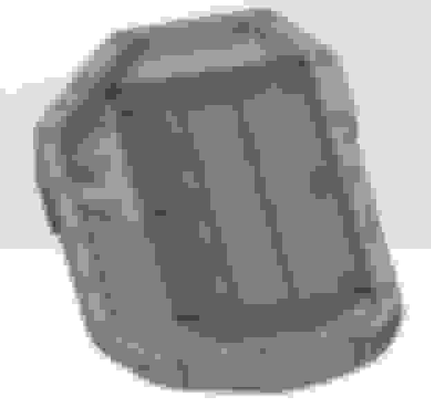
I have the ARE dry sump pan and it is a dumpster fire in terms of fitment. Welder, grinder and a dremel are required to fit it.
Luckily mine is used and has already been modified. I also don't like how you lose all of the transmission bolt mounting points that are in the stock oil pan.
Savington with a three stage you'd have your pressure stage but you want both suction stages pulling from the bottom, and vent the valve cover to the top of the dry sump tank and you won't need to worry about crank case vacuum becoming too strong or about crankcase pressure either. If you are really looking for that extra edge, and want to seal the block and run vacuum, they make vacuum regulators and pop off valves with like 2 or 3 PSI cracking pressure, you'll likely need both, or spend track time with a pressure sensor and trial and error and risk damaging components.
I'd agree with removing oil pump gears and plugging the pickup in the pump housing, and also filter placement. Ideally I would go Pressure Stage > Remote Filter > Thermostat/Oil Cooler > Engine Block.
Also if you put the oil temp sender in the return going into the tank you might get some weird readings from air and also aerated oil foam. Putting it in the oil tank near the bottom would be much more stable.
Luckily mine is used and has already been modified. I also don't like how you lose all of the transmission bolt mounting points that are in the stock oil pan.
Just throwing an idea out there, but could use the NB2 motor mounts that have the additional brace for the transmission?
I have the ARE dry sump pan and it is a dumpster fire in terms of fitment. Welder, grinder and a dremel are required to fit it.
Bummer. Can you elaborate? Dailey has a Mazda application listed on his site but no further details.
Savington with a three stage you'd have your pressure stage but you want both suction stages pulling from the bottom, and vent the valve cover to the top of the dry sump tank and you won't need to worry about crank case vacuum becoming too strong or about crankcase pressure either. If you are really looking for that extra edge, and want to seal the block and run vacuum, they make vacuum regulators and pop off valves with like 2 or 3 PSI cracking pressure, you'll likely need both, or spend track time with a pressure sensor and trial and error and risk damaging components.
Interesting, thanks for that.
I assume you don't want to tee the two pan fittings, since the pump will just suck air if either one goes dry?
So 2 stages at the pan, one pressure stage, and (optionally) one stage at the valve cover with the requisite pressure regulator and safety pop-off valve.
I've been doing heavy research on dry sump design for my K-swap for the past 2 months and I'm almost ready to order a pump and start cutting metal on my oil pan. Not sure where to start with what I've learned.
-Scavenge on the valve cover is pretty uncommon unless the specific engine has oil drainage problems. It's pretty common to see 4 or 5 scavenge stages pulling from the oil pan and zero on the valve cover. V engines sometimes have a scavenge stage pulling from the lifter valley where oil pools, or on the outer sides of the heads since cornering Gs on a V engine can cause oil to migrate back up the head-to-block drainage holes and accumulate in the heads.
-The internet is full of talk about vacuum regulators and pop-off valves, but I've looked at a bunch of dry sump systems on road race cars and haven't seen a single regulator or pop-off valve. Almost 100% of the road race cars I've seen had the valve cover breather hose going straight to the oil tank, and then a separate connection from the oil tank going to a VTA breather can. This makes a closed loop where the scavenge pump pulls air out of the crankcase, pumps it into the oil tank, and then the crankcase vacuum pulls that same air back out of the oil tank and into the valve cover. This still creates a very small vacuum, but not enough that a regulator is needed. And no pop-off needed either since the whole system is VTA. The regulated high vacuum systems seem to be almost exclusively used on crazy drag cars.
-There's definitely some black magic in oil pan and windage tray design. Each of the dry sump companies that I've talked to had very strong opinions about pan design and windage control, but (understandably) wouldn't really share any details with me. The basic feeling that I've gathered is that a bad pan design will pull huge amounts of frothy, aerated oil. A good pan design will do a better job of separating liquid oil from foam. The dry sump oil tank is designed to help separate the air out of the oil with tangential entry and a swirling motion, but it can only do so much during the limited time that the oil is in the tank. A bad pan design is likely to never show itself for short duration racing like autocross or drag, but for road racing, salt flats, boats, and other extended high RPM racing, the oil will slowly get more and more aerated over time and eventually kill the motor. I think a lot of systems hide or get around this problem by using ******* massive oil tanks (3+ gallons) that give the oil tons of time to settle before going back into the engine. (This bullet point is roughly 97% conjecture and 3% fact.)
-Oil pan design should consider the windage below the crank as much as the gravity draining of the oil. Windage forces will cause the oil to primarily pool in one side of the pan, and putting the scavenge pickups on the other side is bad. This was a major point with multiple dry sump companies I talked to so I think it's safe to consider this one fact.
The tight constraints of squeezing a K24 into a stock miata subframe mean that I'm kind of stuck with a shitty pan design. Because of that, I think I've decided to spend a good chunk of money on a Dailey Engineering pump with a built-in air/oil separator. My hope is that the separator will help fix any aeration problems caused by my shitty scavenge design.
We thought that becasue the oil pan is aluminium we would just modify the OEM one, no one else has thought that so presumably there is an issue we haven't thought of with that idea...?
Almost 100% of the road race cars I've seen had the valve cover breather hose going straight to the oil tank, and then a separate connection from the oil tank going to a VTA breather can.
There is a restrictor in the valve cover port though . . . ~1/8". The oil tank and catch can are at atmospheric. The crankcase is at a vacuum due to the action of the scavenge pumps and the restrictor. At least that's how it is on Formula Fords.
I've been toying with a dry sump design that would be easy to make. Basically I'd make it in two parts, the first being a 60mm thick spacer plate / crank girdle that rings the sump and also bolts to all the main bearing caps. Ideally it would be CNC so that the cut outs for the crank can be radial to help windage. It would help a lot to stabilize the main caps.
The second part is just a cover plate that caps off the sump and contains the oil pickup points. It could also have an integrated plate to bolt the dry sump pump.
I know on my car I'd want a 4 stage pump. 2 off the sump, one from the head. With the revs I pull I think there is a lot of oil accumulating in the head which can cause the oil levels in the sump to drop.
I definately think the BP needs a sump baffle if you are reving high and braking at high Gs. I also think accusumps are completely useless on track. They don't stop the oil pickup sucking air.
I have been working through a workaround in my head instead of a dry sump setup. Involves drilling and tapping oil pan towards the very top on both the driver's and passenger's side, adding an fittings then connected to small reservoir of some sort, which then has pickup tubes that are plumbed to the electronic oil pump (similar to differential cooler pump). Use pump controller that triggers pump on over a certain lateral g load, oil that is sloshed against port and sucked up by pump renters the pan thru an additional drilled/tapped port and has a tube that pumps oil back to the oem oil pickup tube. Similar premise to fuel transfer pumps inside oem fuel tanks. Assuming you are doing your own labor, supplies under $1000. Possibly a simple mechanical based system to do the same job to avoid integrating electronics etc.
I have been working through a workaround in my head instead of a dry sump setup. Involves drilling and tapping oil pan towards the very top on both the driver's and passenger's side, adding an fittings then connected to small reservoir of some sort, which then has pickup tubes that are plumbed to the electronic oil pump (similar to differential cooler pump). Use pump controller that triggers pump on over a certain lateral g load, oil that is sloshed against port and sucked up by pump renters the pan thru an additional drilled/tapped port and has a tube that pumps oil back to the oem oil pickup tube. Similar premise to fuel transfer pumps inside oem fuel tanks. Assuming you are doing your own labor, supplies under $1000. Possibly a simple mechanical based system to do the same job to avoid integrating electronics etc.
Possible add baffle similar to 911s or like oem fuel pump sending units but less enclosed..so pumped oil is directed inside the baffle area.
Bummer. Can you elaborate? Dailey has a Mazda application listed on his site but no further details.
Interesting, thanks for that.
I assume you don't want to tee the two pan fittings, since the pump will just suck air if either one goes dry?
So 2 stages at the pan, one pressure stage, and (optionally) one stage at the valve cover with the requisite pressure regulator and safety pop-off valve.
I personally know two other people with ARE pans (for other platforms) and neither of theirs worked out of the box either. It's a known problem (fitment) but since so few people have them that frequent forums, it's like their best kept secret apparently.
On mine, there were a couple holes too close to the pan wall that you could not get a bolt into them with a flat mating surface between flange and bolt head, and if you remove enough material to clearance for the bolt, you go through the pan wall so you have to add in material on the interior wall with a welder before you clearance the holes. Also some of the holes are REALLY close to the outside edge of the flange surface. Seems their castings are not as accurate as they need to be and also they do a poor job of chucking the workpiece properly in their CNC machine that simply drills some holes.
Going back to the mechanics of it, you're correct in not wanting to T the dry sump pan pickups, since one stage might not be able to evacuate oil fast enough and also because of your sucking air concern with one of the pickups uncovered in a T configuration. Usually you want a dedicated line of -10an size minimum for each scavenge stage, and at least a -12an for the oil feed to the pressure side. One other thing to be super careful about is making sure your pressure stage feed and suction stage feed lines are rated for vacuum. I've seen a couple motors blown due to the pressure stage feed line collapsing and starving the engine of oil. Very tricky to diagnose.
Most do not hook up a scavenge stage the the valve cover. Nearly all dry sump systems I've seen on road course and time attack cars vent the valve cover back to the oil tank. Then have a large pipe go to a catch can inside the car from main oil tank, then from that catch can, vent outside the car ending in a filter. This is also where you might want to route lines in a configuration where if the car rolled over, oil would not start to drain out of the dry sump system. It would of course be draining outside the car but still. These pipes are usually something like clear heat resistant tubing in 1.5" diameter range, check McMaster Carr for those.
I've never seen anyone implement a vacuum regulator or pop off valve first hand, that would be "the next level" so to speak in trying to eek out just a little more power but with a decent amount of added failure points and complexity.
Not BP-related, but here's my current K-swap pan design. I wish I could move one of the pickups farther forward, but this design barely fits into the stock subframe as-is. Do a google image search for "dry sump oil pan" and you'll see tons of professionally designed pans with 2 or 3 pickups at the rear and nothing at the front, so I think this will work. Will be machined from a 12x18x2" chunk of aluminum.
Quick and dirty model of the stock K20 windage tray to check clearances:
As it will be installed in the car, with steering rack location and Dailey pump shown. The scavenge hose routing is going to suck but there's not enough room to have fittings exit on the passenger side.
We thought that becasue the oil pan is aluminium we would just modify the OEM one, no one else has thought that so presumably there is an issue we haven't thought of with that idea...?
I think that idea has at least as good a chance of working as my pan design. I would cut/mill the BP oil pan so that it's flush with the bottom of the bellhousing, weld a flat plate over the new hole, and then drill two holes in the side of the pan (intake side, not exhaust) and weld in two of the fittings shown below. I've seen this style fitting used on multiple brands of welded aluminum dry sump pans. Some of the machined pans even use this shape for their scavenge pickups. Just a round tube with the end capped and a flat section milled out, and welded into the pan so that the milled opening faces downward. I would keep the stock BP windage tray.
you'll see tons of professionally designed pans with 2 or 3 pickups at the rear and nothing at the front, so I think this will work.
Interesting.
We run two in the front and one aimed rearwards but its in the center of the engine (flat pan). Packaging constraints don't give us much of a choice, but nothing questionable happens. (not a Miata)
Last edited by MartinezA92; 12-16-2018 at 05:45 PM.
I just looked up the ARE BP pan for the first time. Makes me feel a lot better about my pan design, or the custom welded BP pan idea above. I think I would actually prefer the custom welded OEM pan over this ARE since it would allow you to keep all of the transmission bolts, and since we already know that the Mazda windage tray design works pretty damn well. I'm sure I'm not the only one here who has finished endurance races with nothing showing on the dipstick (aka less than 3 quarts in the engine) and never had an engine failure.

 12-14-2018, 12:20 AM


 2
2