
Full Underbody Kit

 12-11-2017, 11:57 PM
#62
Elite Member

Thread Starter
iTrader: (1)
Join Date: Sep 2016
Location: Seattle
Posts: 1,859
Total Cats: 516
Kinda is the short answer. The volvo fan is a 2 speed fan hi/lo. So with the megasquirt you could wire an extra output to control both speeds.The fan pulls 40-55a draw when you go from off to high speed. Im not sure what the low amp draw is on startup or the spike when it switches to high but i wanted to not have a huge draw all at once. The variable speed controller has a temp range of 160-240 and you can set your min and max temps for the fan and depending on water temp will control fan rpm. Wiring it with the controller eliminates the low speed but turns it into every speed between 60-100% fan rpm and has a soft start feature to eliminate any amp draw spike.
Hope that made sense i started to ramble a bit.
Hope that made sense i started to ramble a bit.

Reply
 0
0

0
 12-12-2017, 09:41 AM
#64
Senior Member
iTrader: (1)

Join Date: Dec 2010
Location: Farmington Hills, MI
Posts: 1,218
Total Cats: 175
You can setup a PWM output with a solid state relay and flyback diode, but MS PWM outputs are really too slow for a DC motor. It'll work, but it'll likely be noisy. I'll be testing out using my JBPerf CAN-EGT+ to PWM my fan and fuel pump, because that board can PWM up to 20kHz, which would smooth out the pulses and act more like a real current control rather than a pulsed motor. You can setup a generic PWM output, where duty cycle is related to 2 axis. So the fan can be related to coolant temp and vehicle speed.
Reply
0
0
12-12-2017, 09:45 AM
#65
Elite Member
Thread Starter
iTrader: (1)
Join Date: Sep 2016
Location: Seattle
Posts: 1,859
Total Cats: 516
You can setup a PWM output with a solid state relay and flyback diode, but MS PWM outputs are really too slow for a DC motor. It'll work, but it'll likely be noisy. I'll be testing out using my JBPerf CAN-EGT+ to PWM my fan and fuel pump, because that board can PWM up to 20kHz, which would smooth out the pulses and act more like a real current control rather than a pulsed motor. You can setup a generic PWM output, where duty cycle is related to 2 axis. So the fan can be related to coolant temp and vehicle speed.
Reply
0
0
12-12-2017, 10:57 AM
#66
Senior Member
iTrader: (1)
Join Date: Dec 2010
Location: Farmington Hills, MI
Posts: 1,218
Total Cats: 175
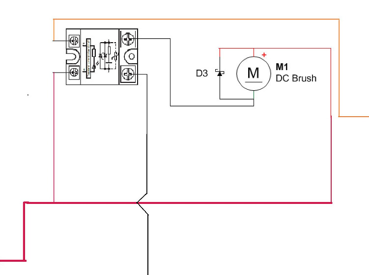
If you set it up as a ground switched PWM, you'd wire 12V to both the positive side of the fan, and the positive side of the SSR coil (well really it's an LED since it's solid state). Wire the PWM output to the ground side of the "coil", the MS PWM outputs already have a transistor output, if you're using a JBPerf board it'll need a protection circuit. Then the switch input of the SSR will go to ground, and the switch output to the motor. It's essentially the same wiring as a regular ground switched relay. Then you need a beefy flyback diode that will allow current to flow from ground to 12V over the motor winding. In the diagram below, orange is PWM output. I'll be using the relay and diode below, both will be mounted on heat sinks. Just a preface that I'm not an electrical engineer, and this is just a culmination of my research, I haven't tested it out yet.
https://www.mouser.com/search/Produc...px?r=558-D1D40
https://www.mouser.com/search/Produc...4045BP-M3%2f4W
https://www.mouser.com/search/Produc...px?r=558-D1D40
https://www.mouser.com/search/Produc...4045BP-M3%2f4W
Reply
0
0


