
Oil cooler tech

 09-14-2015, 12:22 AM
#243

Speaking of which -- I have jury duty tomorrow.

Reply
 0
0

0
09-14-2015, 02:53 PM
#244
Supporting Vendor

iTrader: (3)

Join Date: Jul 2006
Location: San Diego
Posts: 3,303
Total Cats: 1,216
Perfect example of someone knowing how to make a thing, but not when it is an appropriate application.
Those hard lines are a recipe for disaster.
edit: I'm on the late bus, Andrew and Patrick beat me to it.
Those hard lines are a recipe for disaster.
edit: I'm on the late bus, Andrew and Patrick beat me to it.

Last edited by ThePass; 09-14-2015 at 03:34 PM.
Reply
0
0
09-14-2015, 03:42 PM
#245
Boost Pope


iTrader: (8)
Join Date: Sep 2005
Location: Chicago. (The less-murder part.)
Posts: 33,019
Total Cats: 6,587
The link that Mobius provided with data was a street car. OTOH, the Miata oil pan has some pretty significant baffles cast in -- and the point of the baffles is to stagnate some oil so that the pickup still has something to suck under cornering/braking. So . . . ??? I think the jury's still out.
So this is, admittedly, somewhat of an academic question. I just can't see how the oil at any point in the pan is going to be significantly cooler than what's being draw into the pickup tube, baffles or no baffles. The whole point of the oil system is for the oil, all of it, to circulate through the engine.
Reply
0
0
09-15-2015, 01:51 AM
#246

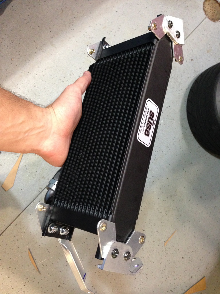
I recently finished installing my oil cooler kit from Trackspeed (19 row) and I thought I would share.
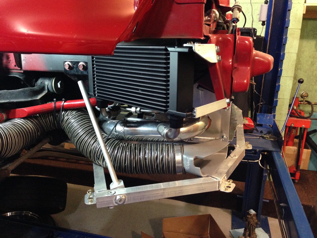
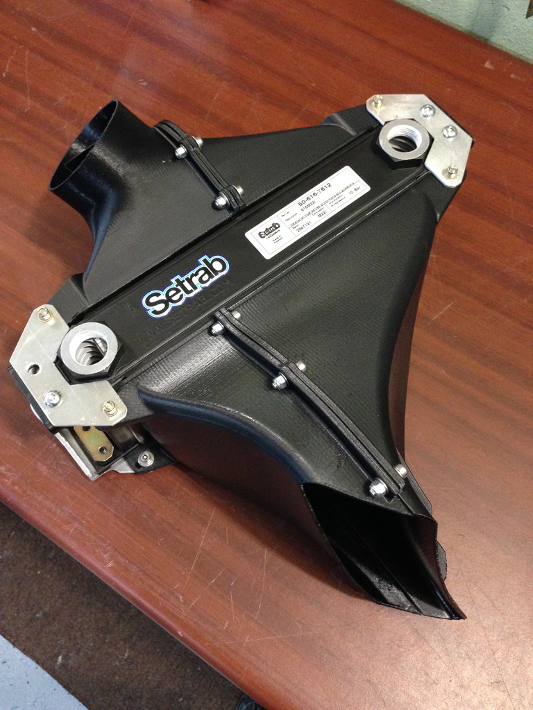
First off, I have an intercooler and A/C already in front of my Koyo 38mm rad. They are fairly well ducted but i was already seeing water temps creeping upward throughout each 20 minute track session without ever leveling off, so i didn't think stacking the oil cooler with the other heat exchangers was a good idea. I decided to put it as high as possible in the front right corner of the car.
Being that the wheel well is a high pressure area with rocks and debris flying around constantly, I decided that ducting the exit air out the front bumper just in front of the wheel would be�better. In other words I stole the idea from Ryan Passey.
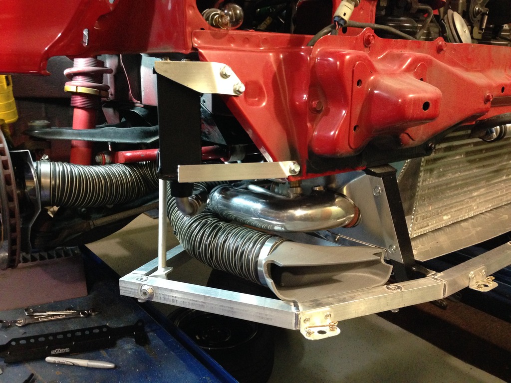
I started out by fabricating the mounting brackets and adding rivet nuts to the chassis to bolt it in. Part of the bracketry was for attaching the duct work.

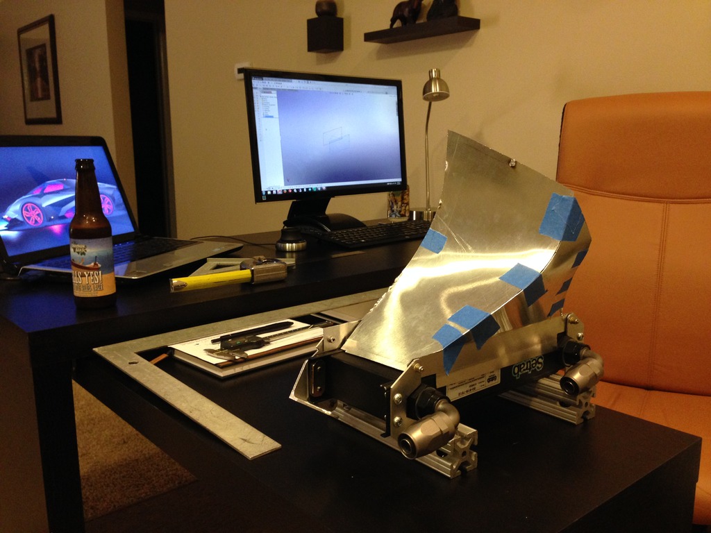
First I attempted to fabricate the ducting from aluminum. I had a feeling I was using too thin of a gauge and it would be hard to weld. I was right - I just don't have the chops to weld .035" alum, so I gave up on welding and took a more "fun" approach


Being that I have a home made 3-D printer in my kitchen, it was the natural choice for plan B. I started out by transferring the measurements off the aluminum prototype into a SolidWorks model. I had to print both the inlet side and the outlet side in two halves, since my build platform is only 8x8x11. It took a few iterations and a couple failed prints but I finally got some decent parts! They are printed from ABS so hopefully it will be able to take the temperature. We will see what happens at the next track day.


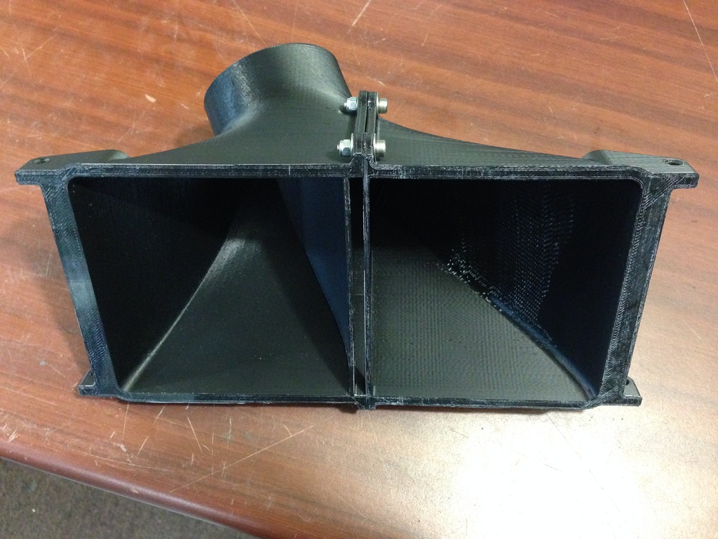


The inlet starts out as a 3" aluminum tube that I mounted to the frame. I cut a hole in the bumper and poked it out. The printed inlet duct is connected to the aluminum tube via a short piece of brake duct hose, which keeps some flexibility in the system in case the front gets bumped (the printed parts really aren't that strong).


First off, I have an intercooler and A/C already in front of my Koyo 38mm rad. They are fairly well ducted but i was already seeing water temps creeping upward throughout each 20 minute track session without ever leveling off, so i didn't think stacking the oil cooler with the other heat exchangers was a good idea. I decided to put it as high as possible in the front right corner of the car.
Being that the wheel well is a high pressure area with rocks and debris flying around constantly, I decided that ducting the exit air out the front bumper just in front of the wheel would be�better. In other words I stole the idea from Ryan Passey.
I started out by fabricating the mounting brackets and adding rivet nuts to the chassis to bolt it in. Part of the bracketry was for attaching the duct work.
First I attempted to fabricate the ducting from aluminum. I had a feeling I was using too thin of a gauge and it would be hard to weld. I was right - I just don't have the chops to weld .035" alum, so I gave up on welding and took a more "fun" approach
Being that I have a home made 3-D printer in my kitchen, it was the natural choice for plan B. I started out by transferring the measurements off the aluminum prototype into a SolidWorks model. I had to print both the inlet side and the outlet side in two halves, since my build platform is only 8x8x11. It took a few iterations and a couple failed prints but I finally got some decent parts! They are printed from ABS so hopefully it will be able to take the temperature. We will see what happens at the next track day.
The inlet starts out as a 3" aluminum tube that I mounted to the frame. I cut a hole in the bumper and poked it out. The printed inlet duct is connected to the aluminum tube via a short piece of brake duct hose, which keeps some flexibility in the system in case the front gets bumped (the printed parts really aren't that strong).
Reply
22
22
 09-15-2015, 03:26 AM
#249
Supporting Vendor
iTrader: (3)
Join Date: Jul 2006
Location: San Diego
Posts: 3,303
Total Cats: 1,216
Dude. Yes. Nice execution, that looks great.
The 3" inlet is a little small for the oil cooler size for ideal flow, but efficiency with the dedicated ducting is so good it'll hardly matter.
Two notes to further improve efficiency:
- Put a small gurney (1/4" height or so) ahead of the outlet.
- Air is already beginning to travel sideways at your inlet location, so the edge of the inlet protruding out of the bumper skin is perfect for the outside half to "catch" the air and direct it into the duct, but it will help to trim the inlet on the inside half to be flush with the bumper so that air can flow inwards easily from its flow direction.
What is the temperature tolerance of the material you printed with? The oil cooler will be over 200* F on the in side.
Reply
0
0
09-15-2015, 09:07 AM
#250
Elite Member
iTrader: (9)
Join Date: Jun 2006
Location: Chesterfield, NJ
Posts: 6,892
Total Cats: 399
Excellent execution MX92'S...damn.
I assume you're homemade printer doesn't print support? If I printed something like that on our Dimension, the entire thing would be support.
I have cheapo autometer temp sensors before & after my 16 row cooler and there's not much delta T, in the noise of the gauge. But my oil temps are now right around water temp whereas before the oil cooler they were 60-70 higher while daily driving.
I found a magnehelic gauge at work that I plan to see what the pressure difference is across my cooler, and see if adding a gurney helps the pressure difference.
Reply
0
0
09-15-2015, 10:43 AM
#252
SADFab Destructive Testing Engineer

iTrader: (5)
Join Date: Apr 2014
Location: Beaverton, USA
Posts: 18,642
Total Cats: 1,866
Excellent execution MX92'S...damn. <br />
<br /><br />
<br />I assume you're homemade printer doesn't print support? If I printed something like that on our Dimension, the entire thing would be support. <br />
<br /><br />
<br />I have cheapo autometer temp sensors before & after my 16 row cooler and there's not much delta T, in the noise of the gauge. But my oil temps are now right around water temp whereas before the oil cooler they were 60-70 higher while daily driving. <br />
<br /><br />
<br />I found a magnehelic gauge at work that I plan to see what the pressure difference is across my cooler, and see if adding a gurney helps the pressure difference.
<br /><br />
<br />That's because dimensions sole goal in life is to **** you in the *** every way possible.
Reply
0
0


 09-15-2015, 01:59 PM
#256
Thanks for all of the compliments - I spend way too much time doing this stuff!!
The printer has a heated build chamber and dual extruders, so it can print HIPS support material with ABS, but it takes a lot longer than printing a single material. For the ducts, I used native ABS support and just tweaked the support/part interface gap until the bond was weak enough that I could just break off the support. Even then, it only supports overhangs that are more than 50 degrees off vertical (adjustable via software) so there isn't really that much support material. I also took the overhang angles into consideration when designing it...notice that the holes are not actually holes but conical dimples.
ABS extrudes at 240C and the build platform is at 110C (the chamber is at 45C). So I figure that the oil cooler fins/brackets may reach a little over 200F, which is going to be right around 100C, well below the melting point. They may, however, soften and sag over time, but that remains to be seen.
I am a mechanical engineer specializing in product development.
Here is a picture of the printer and some CAD screenshots
Reply
0
0
09-15-2015, 02:53 PM
#259
2 Props,3 Dildos,& 1 Cat
iTrader: (8)
Join Date: Jun 2005
Location: Fake Virginia
Posts: 19,338
Total Cats: 573
I clicked on this thread for no good reason.
I come in here and see 3D printed awesome!
We just got a Lulzbot Taz 5 at work. I've been going NUTS with it. It can print a 10x10x10 inch cube (roughly). Realistically a home built printer should be able to compete with that as long as you build it big enough. It's amazing what you can do with aluminum extrusions and some NEMA motors.
Kinda wish I had my own machine at home too.
Reply
0
0
09-15-2015, 04:10 PM
#260
Its roughly 7.75" x 7.75" x 11". The duct print is about the biggest thing I can do, and even then I had to split it in half.
If you start trying to print ABS at these dimensions, you will realize two things:
1. Warping gets more and more troublesome the larger the part gets
2. Things take FOREVER to print. Even at 0.25mm layers, the largest part of the duct took about 18 hours.
If you start trying to print ABS at these dimensions, you will realize two things:
1. Warping gets more and more troublesome the larger the part gets
2. Things take FOREVER to print. Even at 0.25mm layers, the largest part of the duct took about 18 hours.
Reply
0
0


