Bacon's farking useless dual catch can setup
 05-14-2013, 10:24 PM
#1
Junior Member

Thread Starter
Join Date: Jan 2011
Location: Bel Air, MD
Posts: 119
Total Cats: 17
You know why I did this? Because I could. Not for any **** or reasons floating around in your mind, not even one of them. And because I read some interesting stuff on the CTS-V forums about catch cans. And this being where we are, somebubby's gonna say something original like "WTF with 4 lbs of boost who cares?" or "WTF with no ******* turbo who cares?" or some **** about kittens or whatever.
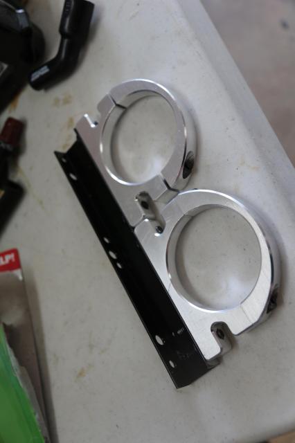
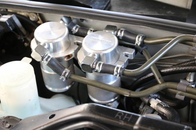
Aluminum C-channel for a bracket for both. There needs to be room for two hoses on the back side and the bracket lets them lay on top of one duh other.
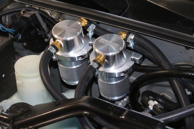
Cans on firewall. I have replacement 90's ordered to get rid of these brassy ones.
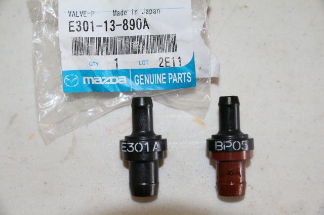
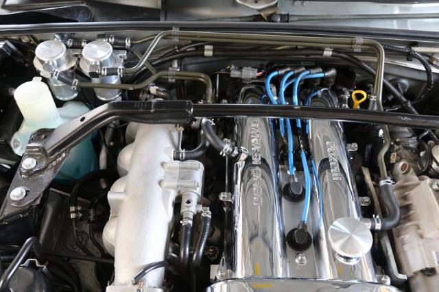
replaced PCV valve with one for 323 GTX turbo
hose layout, which sucks. I will replace this with tubing to keep my "wire tuck" super clean look intact
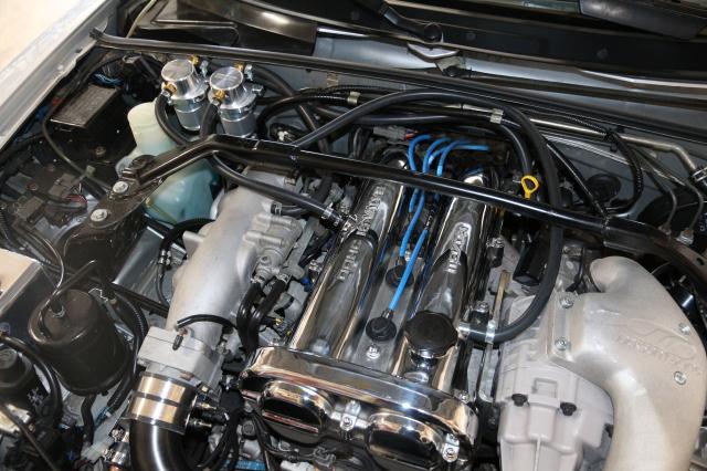
Whole motor, I got rid of my ricer red silicone adapter and replaced with all black.
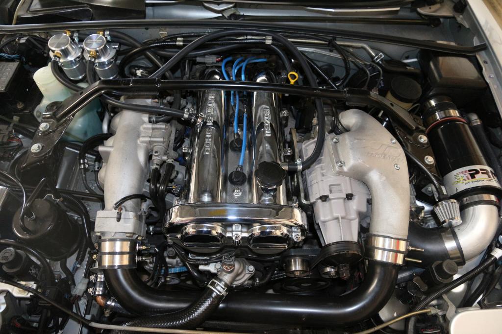
I took this out for a spin and seemed to think: Acceleration was either smoother or stronger. the gauge showed almost 1psi more boost at times. I don't know why that would be. Knock sensor never made a peep, but it was cool today only 63 so maybe there was nothing to knock about anyway.
Aluminum C-channel for a bracket for both. There needs to be room for two hoses on the back side and the bracket lets them lay on top of one duh other.

Cans on firewall. I have replacement 90's ordered to get rid of these brassy ones.

replaced PCV valve with one for 323 GTX turbo

hose layout, which sucks. I will replace this with tubing to keep my "wire tuck" super clean look intact

Whole motor, I got rid of my ricer red silicone adapter and replaced with all black.

I took this out for a spin and seemed to think: Acceleration was either smoother or stronger. the gauge showed almost 1psi more boost at times. I don't know why that would be. Knock sensor never made a peep, but it was cool today only 63 so maybe there was nothing to knock about anyway.

Reply
 3
3

3
05-14-2013, 10:35 PM
#2
Boost Pope

iTrader: (8)
Join Date: Sep 2005
Location: Chicago. (The less-murder part.)
Posts: 33,020
Total Cats: 6,588
We have few content rules here. One of them in "no profanity in thread titles."
(You can swear inside the thread itself all you want.)
I have corrected this, and you shall wear the Pony of Shame as penance for your transgression.
The thread has also been stickied.
(You can swear inside the thread itself all you want.)
I have corrected this, and you shall wear the Pony of Shame as penance for your transgression.
The thread has also been stickied.
Reply
2
2

 05-15-2013, 11:45 AM
#6
Junior Member
Thread Starter
Join Date: Jan 2011
Location: Bel Air, MD
Posts: 119
Total Cats: 17
On the bracket: The trick is to drill access holes in the leg opposite the catch can bracket fasteners for straight shot wrench access to tighten them down
Yes this thread shows how much stuff came out of the cans
http://www.ctsvowners.com/forum/show...Dual-catch-can
Similar thread showing oil that was being entrained into the blower and how the catch can eliminated this
Dual catch can thread as promised - install and very interesting finds
Summer vs winter
Catch Can Contents Summer vs Winter
There's another thread I can't locate that shows the difference of what comes out of each can. Fuel and water condensate out of the non-PVC valve side and heavy oil out of the PCV side.
Another one I ran across that would be relevant to running an intercooler showed how the intercooler got coated with a film of oil on the inside raising IAT at the manifold, and even partially filled it reducing it's volume
Reply
0
0
05-15-2013, 11:50 AM
#7
Junior Member
Thread Starter
Join Date: Jan 2011
Location: Bel Air, MD
Posts: 119
Total Cats: 17
If you mean the catch cans they are closed not open to atm, and they have to reach the connection points, so that's 3/8 silicone vac line plumed and yes those are long. Those will be replaced with tubing because I don't like the look of the line. Length doesn't matter because it's flowing air, all I have to do with each line is make sure each run has a single high point so any condensate drains back and doesn't puddle and block the line.
Reply
0
0
05-15-2013, 01:32 PM
#9
Junior Member
Thread Starter
Join Date: Jan 2011
Location: Bel Air, MD
Posts: 119
Total Cats: 17
Yes at the elbow on the intake side of the blower. On a stock motor this would have been the chrome line snaking around the front of the valve cover to the intake tube.
This tap is pre-blower, but post filter. When the engine is in vacuum mode clean air is drawn in through this side as vapor is drawn into the intake by the PCV valve opening, sort of a fresh air flush. In boost mode the GTX PCV valve should close (is this where my additional boost came from?) and this line's flow reverses as blow by flows out of the valve cover and goes into the intake to be burned in the engine
I think - I think - the purpose of the catch can on the PCV valve side is to keep the intake oil-free under part load when the PCV valve is open, and the one on the valve cover side is to keep oil vapor from going in the intake under boost and lowering the octane, plus keeping blower, piping, (intercooler if you have it) oil free. The two catch cans should oscillate back and forth with regard to which one is catching oil on/off boost.
Last edited by Fukalyal; 05-15-2013 at 02:14 PM.
Reply
0
0
 05-15-2013, 07:30 PM
#14
Elite Member
iTrader: (37)

Join Date: Apr 2010
Location: Very NorCal
Posts: 10,441
Total Cats: 1,899
Yes. As soon as I put the Soopra PCV in my car I picked up 0.8psi errywhere, I even had logs to prove it (until I deleted them) so I could see 1psi being a legit number. Leaky PCV is suxorz.
Reply
0
0
 07-07-2013, 01:38 PM
#16
Junior Member
Thread Starter
Join Date: Jan 2011
Location: Bel Air, MD
Posts: 119
Total Cats: 17
Finished the hard piping setup. I did put the white pill back in the air hose coming from the cam cover and it made a difference in startup (came up to idle right away) and I also think a hair more boost. Without that white orfice / pill it must act as both a vacuum and boost leak.
Materials were 3/8 hose, misc hoses with 90 degree angles in them sourced from hands-on at the auto parts store, 3/8 brake line and some metal clamps to hold the lines together that were originally transmission line clips from a Jeep of some sort.
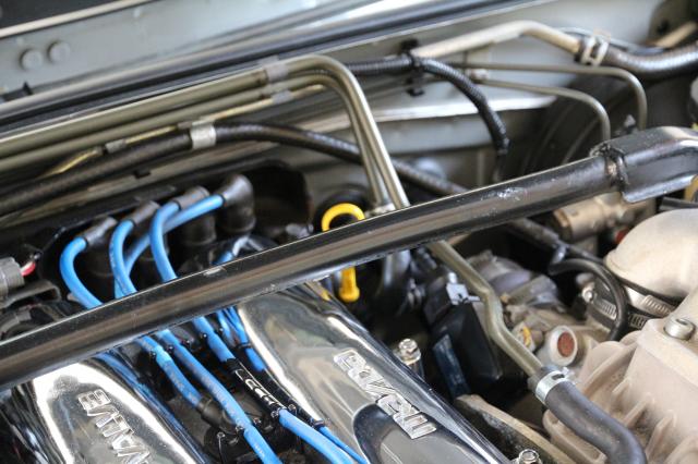
The hard piping was a bit of fussiness but IMHO it looks way better than all that 3/8 hose just laying on top of the motor
Materials were 3/8 hose, misc hoses with 90 degree angles in them sourced from hands-on at the auto parts store, 3/8 brake line and some metal clamps to hold the lines together that were originally transmission line clips from a Jeep of some sort.


The hard piping was a bit of fussiness but IMHO it looks way better than all that 3/8 hose just laying on top of the motor
Reply
1
1


