When you click on links to various merchants on this site and make a purchase, this can result in this site earning a commission. Affiliate programs and affiliations include, but are not limited to, the eBay Partner Network.
Given I have access to a CNC machine I thought I might make some lightweight billet front spindles. Borrowing from the design of the Keisler drop spindles, I figured I'd design it around the MR2 Spyder hubs since they are easy to source and have an inbuilt speed sensor which might come in handy. I also need to credit the locost wiki site for providing 3D models of the stock hub which was a great starting point for the design as well as Leafy for providing me with some initial design feedback.
My goals are to make a nice light spindle and at the same time design it around the MR2 hubs, add in 2.5 degrees of camber and if possible hard mount my dynapro calipers. I don't particularly need a drop spindle however it would be easy modify the design to incorporate a 20mm drop... I was even wondering if I should add a second mount point for the hub so that I can try it. In terms of the steering arm connection, I'll make up some rod end connectors that screw into the threaded ends of the steering rack arms. This means there is less of a concern regarding angle of the ball joint and it will be lower profile too. I can also easily modify the pivot point with the use of spacers.
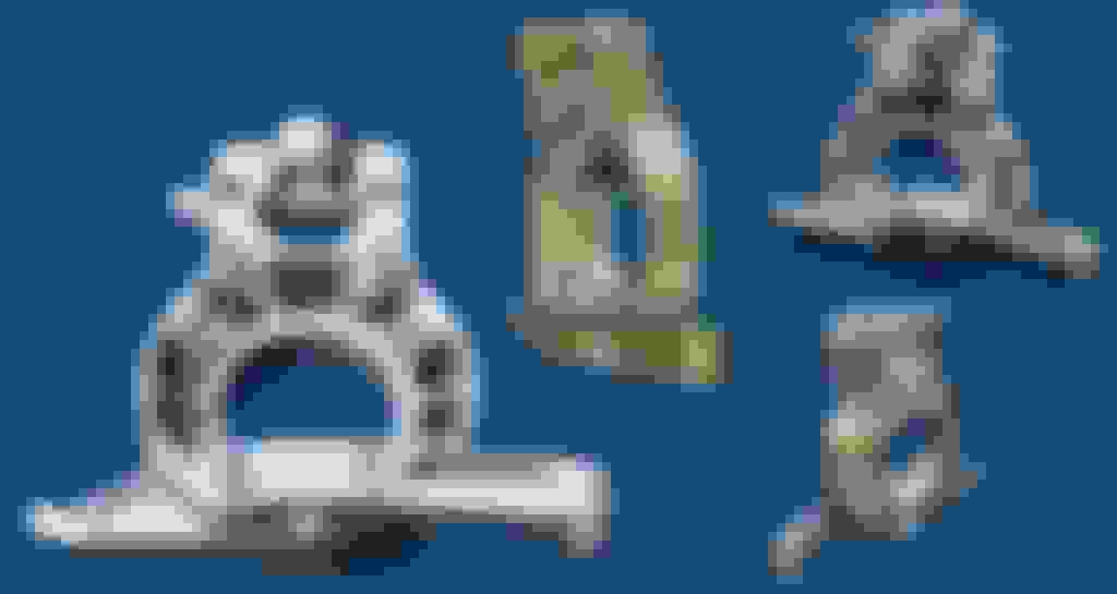
Design no1:
This design was based on something I found online. The idea here is that everything could be CNC cut out of thick plates and bolted together. It would need the mating faces to be machined and maybe doweled as well as high grade bolts. I still like this design as it is so easy to make. If I continued down this path I'd thicken the base plate a lot to give it way more strength and it would also reduce the canter-levered suspension mounts. Maybe I could brace these with a similar idea to Concept no2.
Design no2:
Just a quick sketch. The idea here was an evolution of design no1, with the a solid central billet 'T'ing onto the steering arm piece and tying the two suspension connections together.
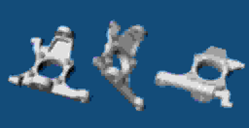
Design no3:
This was my starting point for what would be a solid billet design. This looked far too flimsy through the guts of the hub and would need a truss backing to reinforce the structure which moved me towards my last design conept no4.
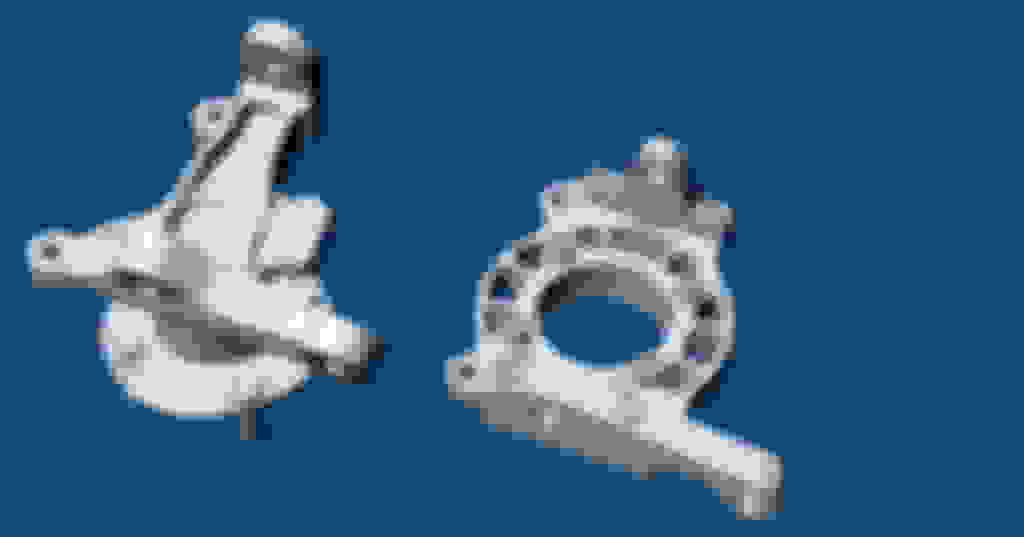
Design No4:
This design looks good and is the lightest design so far weighing in at around 650 grams. It is a single billet at nearly 75mm thick that includes the Dynapro caliper mounts. Looking at the design, I think the central ring around the hub needs some additional material on the sides as well as some thicker ribs to the top ball joint. I'll also need to add some mounting points for some brake ducting. I need to get my hands on some FEA software so that I can see where the stress points are and I can evolve the design. This concept well require a whole stack of machining time cutting away the waste material, but the end result will be awesome.
Anyone have some comments / concerns before I start prototyping? Just a couple of notes is that my rapid 3D modelling doesn't include any radiused interior cuts. I will add these in as I further develop the model.
yeah I liked the idea of bolting on the steeing arm as per designs no1 and 2. It makes it easy to machine and easy to change if required. The big concerns that the load on the top and bottom suspension flanges is massive and making that connection safe is my concern with this design. I designed No1 as a drop spindle, so bringing this back to stock ride height will give me a larger area to attach the top ball joint and maybe give it some additional bracing. Also adding in the additional 2.5 degrees of camber will reduce the cantilever forces on the top joint. I might re-visit this design tonight when I get a chance.
How does the size of the MR2 wheel bearing compare to the Miata?
I'm not actually sure. I've ordered a pair of OEM hubs from a wrecker so I can do my prototyping.
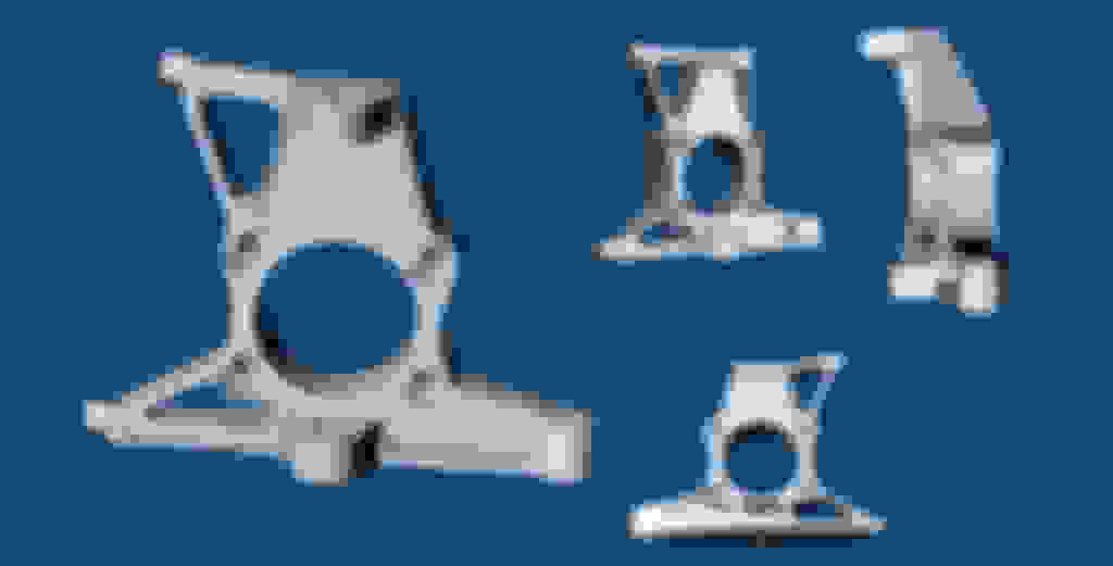
I've re-worked my first concept and made it a bit more solid. I think it still needs lots of work but it looks pretty damn epic! It's designed to fit into a 35mm thick billet so it's easy for me to machine. The top ball joint connector needs some work so that the bracing runs more to the actual mount point. The brake mount also needs some attention but overall I'm really liking the look of this design. All up around 850 grams.
edit: with this design I can add some packing spacers to the top ball joint bracket to alter the camber a bit. I will also key the bottom steering arm where it connects to the main body of the spindle so that all the shear loads go through a a couple of locating rings rather than the bolts which are just applying a clamping load. This won't be packable due to the extremely high loads but replaceable steering arms could be handy for suspension tweaking.
Because they are custom I can do whatever brake mounting points are needed. I have dynapro calipers already though so I'll stick with those for now. I could make the caliper mounts bolt on so they can be interchanged but that reduces rigidity a lot.
Any idea on what kind of corner/bump forces we see in a Miata? How are these files saved? Can they be thrown into ABAQUS?
It's all modelled in Rhino3D so I can export as IGES, STEP and mesh formats. What do you need it in? PM me your email and I'll send you a few models.
If you take the weight of 250kg on the front tyre for the mass of the vehicle. We can acheive around 1.3G under braking plus dipping through a corner and hitting a kerb. So I'd guess at 10x - 20x the static load for dynamic loading which would be mostly vertical but with a bit of sideways loading also? There is also a secondary force generated axially by the caliper.
I can try with an IGES file, but you'd have to tell me what units you're working with so all forces can be scaled appropriately. ABAQUS doesn't use units, but will take measurements at face value. If I know everything is in reference to meters, that makes life easy. If mm or inch, then conversion has to be made for the numbers to reflect the units.
For instance, 1Pa becomes:
0.000001 N/mm^2
or 0.00014503773773 psi
If it isn't too much to copy and scale everything in terms of meter, that make life a bit easier in terms of understanding results. Also, what material are you using exactly?
I'll have to see if my copy still runs at home, otherwise I might have to sneak something into work on off times.
One complication with MR2 hubs is the flange face OD is slightly larger than the Miata's, so you may need to make custom rotor hats. Not the end of the world given your resources but good to note.
I would definitely make the caliper mounts modular. Don't design the whole thing around a basic budget caliper just because that's what you have right now. Future-proof your design.
Find a spherical bearing rod end available with the correct female metric threads to match the steering rack end (M10 I'm guessing off the top of my head?) and do the steering arm around that rod end.
You really should confirm everything you got off that locust model. I used it when laying out the suspension arms and playing with them and They're not quite right. I had to tweak them to make the alignment match real life.
These are just concept models at this stage. They were modelled rapidly to test my ideas so a final 3D model will be built from scratch once I decide on the best design. Most of these concept were modelled within a few hours, so they are very rough around the edges but are fine for volume calcs and to get an idea of structure. The final model will be far more finessed, with nice fillets / chamfer etc all over it. I really like 3D organic forms so I might go all out and smooth oall surfaces to make it organic. Anyone who has done 3D prototyping / modelling will know how time consuming that is to do and a small design tweak can require a complete rework so you need to have a firm base design.
I'll need to confirm mounting dimensions, hub centerlines, hub bolt holes (once I have one), etc etc. I'll also make a prototype out of something easy to machine like chemiwood so I can test fit and double check all the geometry. The chemiwood is ideal as it's strength is just enough to test rigidity with your hands but still bolt things up to it. I'll be able to bend and break the prototype model I'll know where the weak point is on the design.
I need to decide if I'll go with Concept No1, or concept No4. I like the modular design of No1 as it's very easy for me to make. I can get the base structure waterjet cut first then load it up in my CNC to finish. I can also make different steering arms and brake mounts to fix alignment issues if I need to. No4 will require a massive billet and I need to get it right first go, with a single mistake requiring it to be remade from scratch. My CNC machine is a little hobby machine so it isn't suited to cutting from a single big billet, but I do have access to a workshop with a big machine.

 09-06-2016, 04:45 AM


 0
0