When you click on links to various merchants on this site and make a purchase, this can result in this site earning a commission. Affiliate programs and affiliations include, but are not limited to, the eBay Partner Network.
This is totally rad. Thanks for posting your work!
A few questions from a suspension noob...:
1. How accurate does the angle of the fixed bolt need to be in relation to the clevis pin? I guess it would all come down to how much adjustment you can make?
2. I have no idea what the range of motion on a heim is. If you were to make the ball joint holder piece a little wider would it enable you to use the 1/2" units? (No idea what the constraints are on that size)
2b. After you informed us that this is common practice, I noticed that other versions of these have bends here and there to account for articulation. Do you think a bend would hinder the strength enough to where using the 3/8" heim is a better option?
3. Any plans to attack the rear upper arms?
1. Not very, the adjustable links allow you make up for any slight variations. Honestly you'll find more variance in the upper control arm mounts on the sub frame which is one of the reasons I built these. I've measured 4 subframes biw and the variance can be near a 1/4" in the spread from side to side.
2. Heims generally have a little over 30 deg articulation, making the ball joint knuckle wider would help this, but not enough to eliminate the need for high misalignment adapters. If you're concerned with strength then I would look at using 5/8" heims and a half inch bolt with the marginal spacers.
2b. Bent arms wouldn't allow you to make adjustment, not enough room to the shock to swing a curved tube.
I would think it would depend on the diameter of the shank. There's gotta be a shank diameter for any load where it doesn't matter that it's threaded.
The "Rod Ends in Bending" pic shows the rod end being used in a geometry where it's more likely to exceed the heim's range of motion than it is to bend the shank (although exceeding the range of motion would put an additional load on the shank).
I agree there is a diameter of threaded rod that will be ok, I can tell you it's much larger than 3/4". Trying to make reducing bushings for a 1 1/4" or larger heim just gets to be silly though.
While exceeding the range of motion is a sure way to snap a heim I can assure you the author of that article is talking about a bending moment on the heim, it's bad, it breaks stuff. Formula SAE is a competition amoung engineering schools and the gent on that link is one of the judges.....he says don't do it........I didn't listen and we snapped a 3/4" heim on a 400 lb. vehicle trying to use it on the outer end of the lower a-arm and snapped several 5/8" heims on the inner side. Don't do what I did.
Update: Been driving this to work for the past 2 weeks and I've logged ~1000 miles so far. This includes some knarly road work area's with 2" verticle cuts in the pavement where they were getting ready to lay new asphault to the old. No sign of failure.
Last edited by Bronson M; Sep 22, 2016 at 09:42 PM.
Shrug. My old Mustang's rear trailing LCAs have threaded heims on one end (poly on the other). Although I don't personally have any vertical loads on the arm, they're designed to have one for the rear spring (I happen to have coilovers which relocate the spring load). They're 1.5"x0.120" tubing with 3/4" rod ends.
I did not, upper arms don't weight much so weight savings was never the intent of this project. I would imagine any weight difference would be in ounces not pounds.
So it's been over a year since I updated this thread.......so far nothing has fallen off the car. A recent inspection found the heims still wet with grease and no additional slop in any of the connections. I've adjusted alignment multiple times and man has it been nice.
On to the new project, I've been wanting to do adjustable upper arms in the rear for a while now, mainly because trying to adjust camber and keep the toe in line is a royal pain the rear and often times can be a compromise. Trackside adjustments are a no go as well. Since I'm running more power I've wanted to stiffen all the bushings in the rear as well and this was a good opportunity to do so. In an ideal world I would have took the time to fab or buy spherical bearings for the inner pivots and I may still do so in the future. For now they are poly with delrin in all the outer positions.
I actually purchased a lot of the hardware for the rear when I fab'd the front a-arms. So this was the general idea.
Concerns were clearance to the shocks as well as spacing the inner pivots wide enough to build a true A-arm to resist lateral movement (braking and acceleration). The outer clevis' will clamp the plate as shown, but combined with a delrin bushing in the spindle the bracket will not be able to rotate. There are adjustable a-arms out there that utilize a single adjustment near the spindle, I don't like these because you have to rely on the inner pivots to flex based on your toe settings since the spindle can move laterally depending on settings. You can see my oem arm actually has the bushings pushed out to one side because of this. The idea is you would disconnect one link and make your camber adjustments, then attach the other link with zero pre-load so you there is no bind.
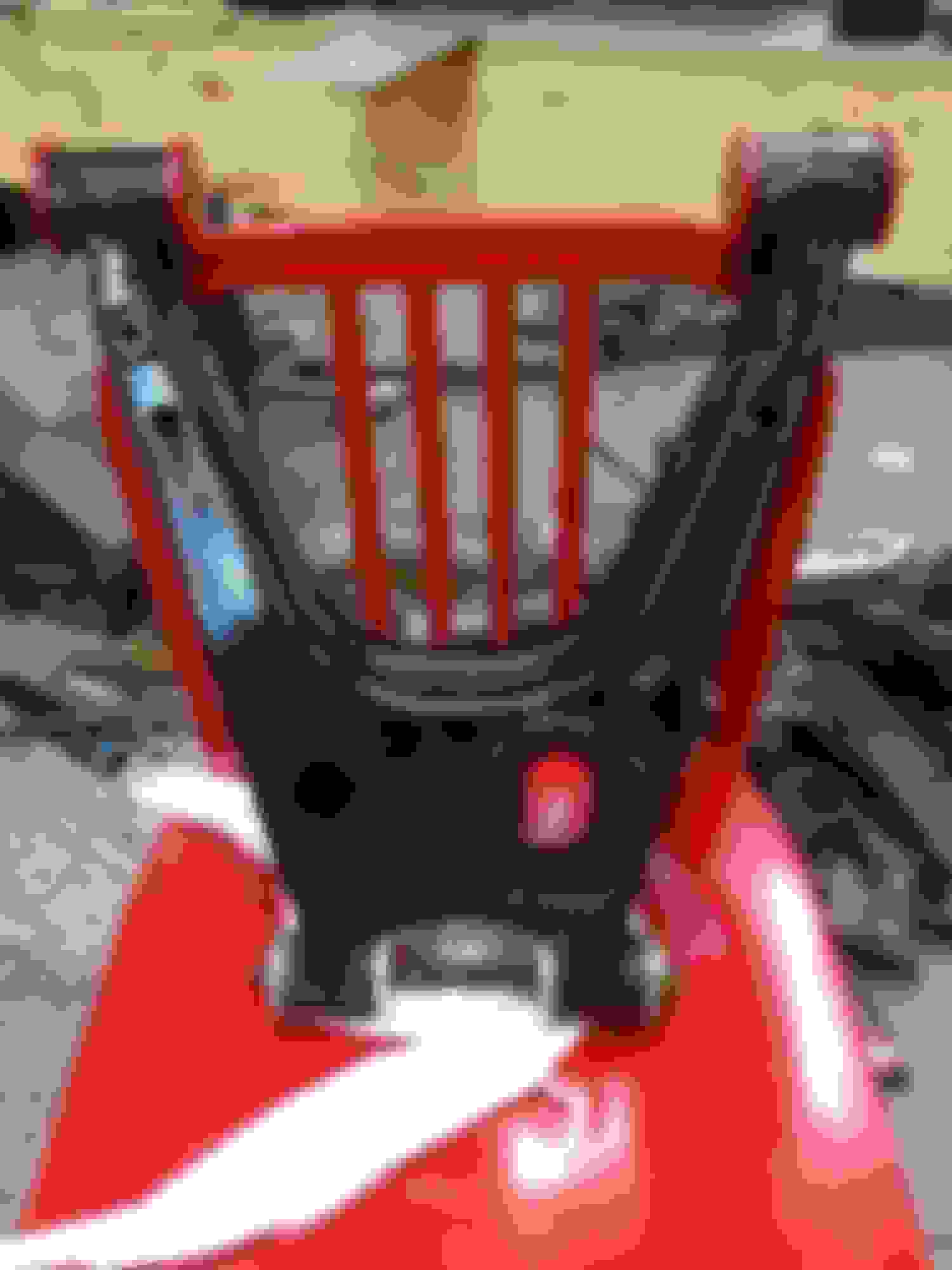
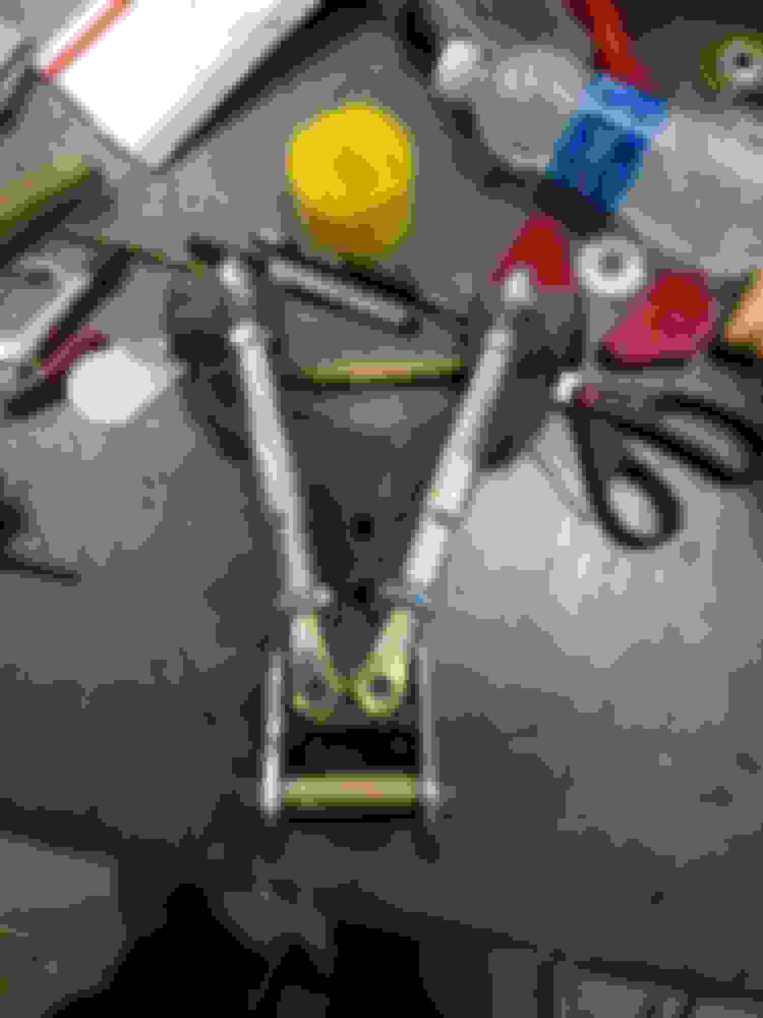
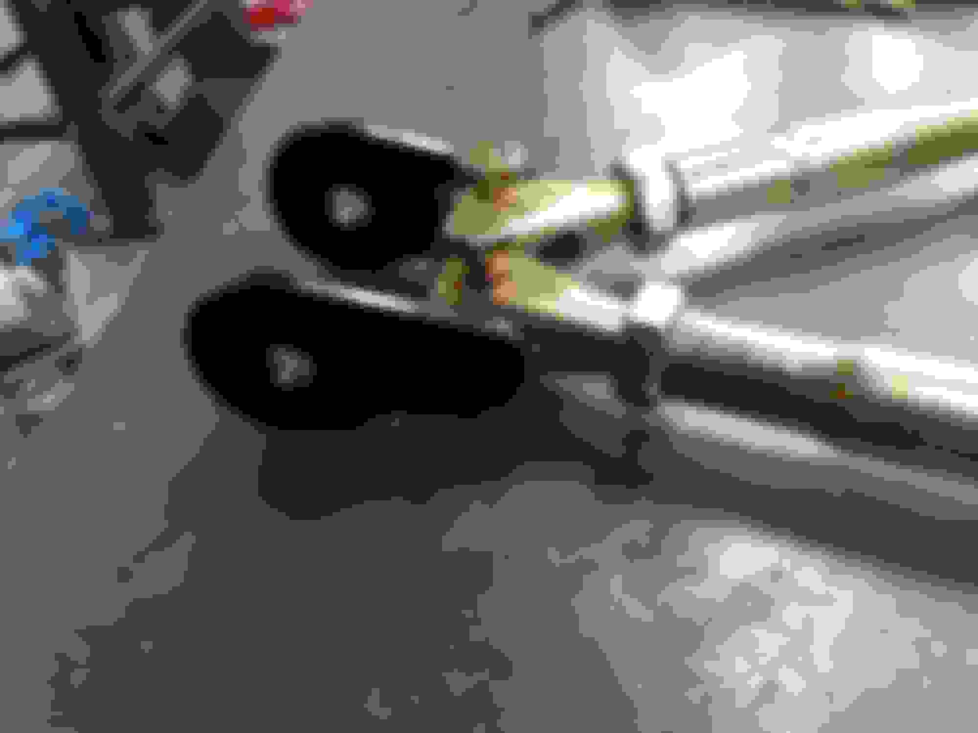
Finished product with one inner joint exploded. Those are high misalignment bushings that were machined to fit the metric fasteners, and a simple spacer.
Better shot of the bracket.
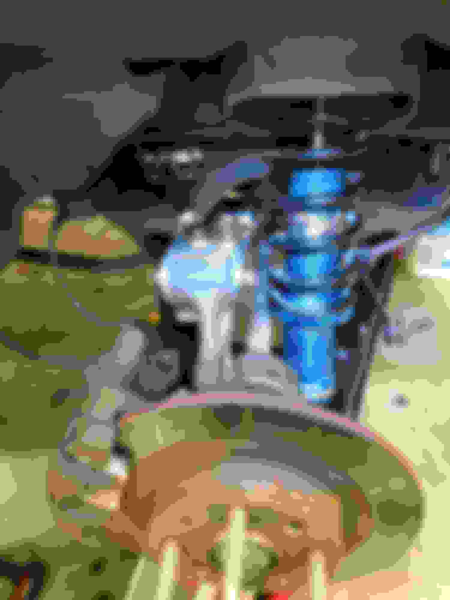
As installed:
I'll let you know how the first alignment session goes.
If the bolts holding the clevii to the plate were loose and the upright was not connected to the lower control arm, it would be able to twist. It's a rectangle with nothing constraining twisting other than clamp load. Granted, the clamp load is probably sufficient that the friction plus rotational resistance from the lower bolt won't cause it to twist, but it's still possible. The front control arm cannot rotate like this because it only has 1 clevis.
So yes, rotation in top view plane is only resisted by the clamping load and the lower bolt. The lower H arm is actually very strong in that plane. Compared to the stock rubber bushing, it's way better.
I'm more concerned with rotation in the side view plane since acceleration will rotate towards the front of the car and braking to the rear. The lower H arm is not very strong in this situation. With the delrin upper bushing this setup will make for a much stronger setup. I'm hoping this will reduce or eliminate the axle hop I sometimes get launching the car.
Ryan, I'm using lock nuts so the heim shouldn't twist on the threads.
Nice work, looks super functional. Although, mixing metric and imperial bits on one car would drive me insane!
It makes my eye twitch..... But metric heims are rare and expensive. Clevis, Reducing bushings, and threaded tube is non existent so here we are.
When I go to the track I electrical tape groups of tools together for common tasks so can grab them and go since I'm usually in a hurry. So the alignment bundle has the proper std. Wrenches with any metric tools needed.
/\ I feel that pain. Whenever possible I utilize SAE 3/6-16 hex hardware since the 9/16" head is close enough to pretend its 14mm. And it makes cheap HF china wrenches feel like snap-ons lol


 0
0