When you click on links to various merchants on this site and make a purchase, this can result in this site earning a commission. Affiliate programs and affiliations include, but are not limited to, the eBay Partner Network.
I'm running a 5 speed dog box in my car and the manual shifting is difficult for sprints and launches. It's a circuit based box so it has 1st in the standard 5th location above reverse so that 2nd through to 5th are in the left most 'H'. This becomes an issue for fast launching as the shift from 1st to 2nd is slow. It's also a major risk on the circuit due to the way miatas like to go from 2nd to 5th on a traditional box. If I do that same miss-shift with my dog box it's game over for the engine as I'll be popping it into 1st without a clutch. To mitigate this I have added a much stronger centering spring on the shifter mechanism to make it hard to miss-shift into the far right gates. It's ok but I'm still worried about it.
So I thought up a design project. Why not make a mechanical shifter that converts a sequential shift motion to a H pattern shift. I have been going around in circles with lots of different designs and I ended up on something I think would work. It's fairly elegant with only a couple of moving parts, but it will be hard to get right and tweak.
BUT then I watched a video of a Mini with an Evo engine and a Pneumatic sequential shift and I figured... why go for a mechanical solution when I could shoot straight for gold. May as well go all high tech and build a pneumatic solution. An hour of googling later and I've ordered the following on ebay:
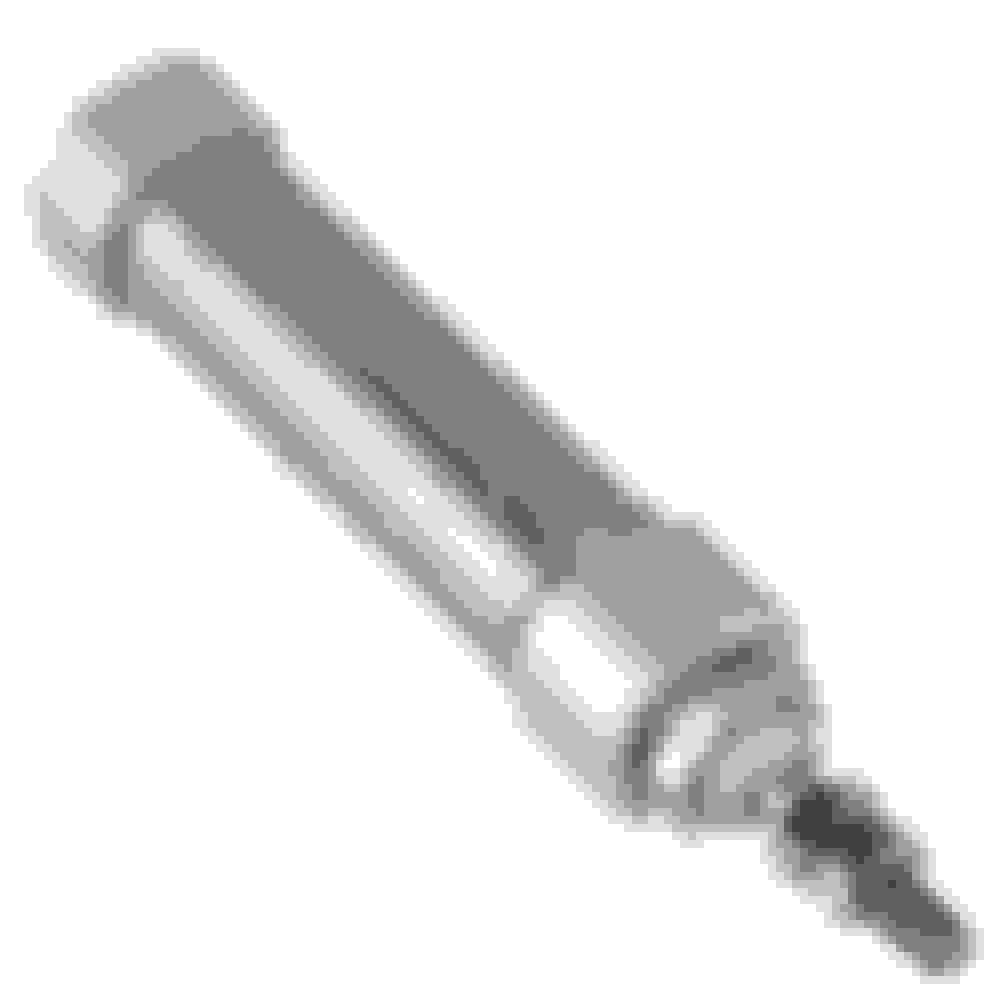
4 x 16mm bore 25mm stroke dual action air cylinders
4 x 5 port 4 way pneumatic valves
20 elbow fittings and some 8mm tube
All up only $70USD
The concept is fairly simple. I'll control the pneumatics with an Arduino that is basically switching the 4 valves in preset sequences up and down. 2 pneumatic cylinders will be paired sequentially in two sets (Up - Down / Left - Right) with each cylinder moving the shifter the equivalent of 1/2 a shift. In this way I can make the selector move down from 1st to N by retracting one of the two up/down cylinders, move across to the left two gates by opening both left/right cylinders then back up to 2nd by opening the up/down cylinder. All of this should happen in the blink of an eye... in theory. I'll also need an air compressor and tank but for now I'm going to bench test this concept and my workshop compressor.
I've never worked with pneumatics or Arduino so it's going to be a bit of a steep earning curve to get it all to work but nothing to tricky hopefully. I'll need a good amount of custom fab to build all the required linkages but I figure I can place it on the passenger floor and use cables for shifting to keep things easier for now. Initially I'll push and pull on the shift lever as its easier but will eventually move the mechanism to act directly on the shifter input bar. I don't want to drive the shift forks themselves as mechanical interlocking is very important if there is an issue with the electronics, but I could make my own interlock mechanism I suppose. First stage is a simple proof of concept.
Have any of you played with pneumatics controlled by ardiuno before? It would be useful to have someone to bounce ideas off.
With a mechanical shifter you would still get feedback from the transmission and you'd never ram in a gear when it wasn't ready for it, but with pneumatic you'd have to be very careful and only 'push the button' when the box was ready to avoid game over?
With a mechanical shifter you would still get feedback from the transmission and you'd never ram in a gear when it wasn't ready for it, but with pneumatic you'd have to be very careful and only 'push the button' when the box was ready to avoid game over?
With a dog box you don't get that luxury. If you are changing gears without the clutch it will go into any gear especially if shifting hard and fast which you have to do to make to dogs engage cleanly. If shifting with the clutch you get the opportunity to feel the engine load and reengage it but then you are losing shift time.
The arduino controller could read the CAN output from the ecu and decode the rpm bits. It would also need the vehicle speed. Then you can do more interesting things like hold a downshift command until the target revs are acceptable or even auto change under braking (like preselect a low gear for an upcoming cirner and the controller holds the gears until the vehicle speed drops).
I think I might need to drive the clutch with an actuator in that case as I currently need to tap the clutch to unload the dogs to get it out of gear due to the high backcut on the dogs.
You might check out Formula SAE/Formula Student builds, there are a lot of cars out there that use pneumatic/electronic shifters with Arduino. My team did an electronic one, but I was not a part of that project
You might check out Formula SAE/Formula Student builds, there are a lot of cars out there that use pneumatic/electronic shifters with Arduino. My team did an electronic one, but I was not a part of that project
FSAE shifters are much simpler. Bike motors only need a single rotation to shift, so a lever arm and single pneumatic actuator. We didn't need any controls for ours, just a single solenoid, and single actuator. The driver would just hold the button until the shift completed. Most standalone ECU's have the capability of controlling a bike shifter as well. It basically just actuated the solenoid until the sensor indicates a completed shift, while retarding spark.
Madjak, are you planning on keeping the mechanical portion of your shifter, and just use air cylinders to actuate the single lever arm forward and back? Or are you using the cylinders to position the shifter throughout the H pattern? You should check out the Mastershift system just for some inspiration. They use push pull cables with electric actuators remote located in the trunk. Their controls are interesting that you tap the up-shift before you need it, and it puts the up-shift on queue until it detects the clutch. So basically hit the upshift at say 6000 rpm, then just stab the clutch at 7000 and the shift happens.
Cool project. Very ambitious but very cool. Who made your gearbox? I've never seen it before where 1st is where 5th normally is. I've seen other transmissions with "dogleg" gear shifts where 1st and reverse are near each other, but never where 1st and 5th are swapped while selecting 2-4 remain the same.
In FIRST Robotics Competition teams do a lot with Bimba pneumatic cylinders, CTR Pneumatic Control Module, National Instruments roboRIO and Labview, and all the other stuff that it takes to make a functioning pneumatic actuator system like compressor, accumulator, solenoids, fittings, tubing, etc. I don't know that it's automotive or motorsports grade stuff, but it's a start. Take a look at Andy Mark and Chief Delphi and US First Robotics Competition Forums and National Instruments FRC Forums. I'm sure there are many similar resources available in Australia as FRC is a global phenomenon. Like Megasquirt, be prepared to do a lot of reading and research before you start to get the hang of it. Good luck!
Madjak, are you planning on keeping the mechanical portion of your shifter, and just use air cylinders to actuate the single lever arm forward and back? Or are you using the cylinders to position the shifter throughout the H pattern? You should check out the Mastershift system just for some inspiration. They use push pull cables with electric actuators remote located in the trunk. Their controls are interesting that you tap the up-shift before you need it, and it puts the up-shift on queue until it detects the clutch. So basically hit the upshift at say 6000 rpm, then just stab the clutch at 7000 and the shift happens.
First step I was thinking of just actuation the shifter so I can see and feel if and how it engages. The linkages are the easiest to design and I can easily modify the stock shifter to attach the gear cables to. Movement in this case is simply left right and up and down so no need to make anything complex.
The second step will be to remove the entire shifter and turret casing from the gearbox (5 speed it just unbolts) and then make a lever based assembly that mounts to the same holes that moves the main shifter rod forwards and backwards and rotates it to select the various gates. This should make it a bit easier for the system to shift as there is less friction and slop.
You can get some awesome 3 position air cylinders that would be ideal as they simplify the design and you can customise the lengths of each stage when ordering. I don't know what bore or stroke I need yet so I'm going to prototype with the $5 ones one ebay then once I know the specs order the $200 multi position cylinders.
When I measured the 6 speed gates they are all slightly different spaceing so being able to order cylinders in 1mm increments becomes more important. I think the 5 speed box as more equal spacings which helps me with my el cheapo cylinders. With the ebay cylinders I can scale the leverage of the entire axis but not each stage independently. Pneumatics are on / off at a designed length, there is no fast way to stop them at 85% travel.
With the automation, I still want to drive the car and not make it fully automatic. I could program a target gear per corner based on GPS and let the gears change based on optimal power / revs but I think that takes too much away from driving.
For now it's just going to cycle through gears up and down. Spark cut, clutch control can come later.
I made a thread about this about a year ago or so. It's doable. My design I was going to use pneumatic actuators with linear potentiometers to measure position so when I tell it to shift, it can measure position of the shift in realtime so it never misses a shift for any reason. Some microcontroller to handle logic, arduino would be fine for this. Clutch done by an actuator as well. After thinking about it I swapped in an auto instead, then another, then a Ford auto. Funny enough the Ford auto has a sequential shifter, lol, and shifts in probably 20ms. It's stupid fast. If you got any arduino or control system questions let me know.
I made a thread about this about a year ago or so. It's doable. My design I was going to use pneumatic actuators with linear potentiometers to measure position so when I tell it to shift, it can measure position of the shift in realtime so it never misses a shift for any reason. Some microcontroller to handle logic, arduino would be fine for this. Clutch done by an actuator as well. After thinking about it I swapped in an auto instead, then another, then a Ford auto. Funny enough the Ford auto has a sequential shifter, lol, and shifts in probably 20ms. It's stupid fast. If you got any arduino or control system questions let me know.
Thanks Pat... I've been following your thread closely. I think the area I'll have difficulties is in the arduino and electrical side of things. The mechanical linkages and fab won't be an issue. The Pneumatics themselves are actually fairly straight forward so other than choosing the appropriate valves and sizing the air cylinders it's just a matter of connecting them up correctly.
I was thinking of setting up some sort of contact sensor at each shifter location to signal a successful change, but I suppose the linear potentiometer is far more flexible. They aren't cheap though!
If you got electrical questions too, let me know. I have a fair amount of experience with car electronics and control systems. I'd love to see you build this and get it working! I have no regrets on putting a strong auto in my car, but I do wish I'd built the pneumatic system just to see how well it would work. So getting to see you build it and test it out would be very cool to see.
A mechanical switch could work too. I figured for me that linear pots would be easier to setup/calibrate, etc. Then you can datalog the motion as well to allow for adjusting pressure or dampening as needed. They cost more but I'd do them if they aren't too expensive. I don't remember what they actually cost, haven't used one in years.
If you got electrical questions too, let me know. I have a fair amount of experience with car electronics and control systems. I'd love to see you build this and get it working! I have no regrets on putting a strong auto in my car, but I do wish I'd built the pneumatic system just to see how well it would work. So getting to see you build it and test it out would be very cool to see.
I don't have the power band that you have, so I need the rev drop between gears to be as small as possible. Unfortunately that means I have lots of gear changes so saving time between shifts will help a lot.
Here are the specs on the box, although mine is dog engagement for 1st. Check out how close 2nd to 5th are.
For circuit racers who require close ratios with a 1.0 top gear, we have a dog leg style gearset available. The standard 5th gear is replaced by a new synchromesh engagement first gear and all of the old 1st~4th gears are moved up to 2nd~5th. This configuration allows the driver to start off in first gear which is in the std factory 5th position on the H-Shift. Once moving, 2nd gear is engaged by moving the shift down and over to the factory 1st gear position. The 1st synchromesh, 2nd~5th dog engagement configuration provides the flexibilty of a close ratio gearset, shifting speed and positive selection of a full racing transmission in addition to easy selection of 1st gear when stationary.
Features:
� Tooth profiles that reduce noise, wear and load forces on the standard OEM transmission housing
� Multiple piece layshaft shaft for flexible ratio choice and changes
� Straight cut gears for maximum power transmission and minimal thrust loads exerted on the OEM transmission case
� Billet Shift Fork included
A mechanical switch could work too. I figured for me that linear pots would be easier to setup/calibrate, etc. Then you can datalog the motion as well to allow for adjusting pressure or dampening as needed. They cost more but I'd do them if they aren't too expensive. I don't remember what they actually cost, haven't used one in years.
The cheapest I can find are around $200 each. I think some cars came out with them so I'll see if I can find some second hand ones.
I did make a 3D printed lever arm for a rotary potentiometer for suspension ride height that I never ran. Maybe I could get a couple of them to work...
if you haven't already. I'd almost be tempted to use 3 pairs of cylinders and work the shift rods directly once you have the control algorithms worked out.
One thing you don't seem to know about is "switch ready" cylinders - there's a magnet embedded in the piston and you have a reed switch on the outside of the cylinder (or non-contact version) to tell you if the piston is at a given location.
Oh hey, I thought about this too, though it's not legal for the class I want to build for. Check out https://www.youtube.com/watch?v=Cj3XqVR5yig if you haven't already. I'd almost be tempted to use 3 pairs of cylinders and work the shift rods directly once you have the control algorithms worked out.
One thing you don't seem to know about is "switch ready" cylinders - there's a magnet embedded in the piston and you have a reed switch on the outside of the cylinder (or non-contact version) to tell you if the piston is at a given location.
I am tempted to directly drive the shift forks but if anything goes wrong it's likely that two gears could be engaged at once. I still want a mechanical interlock and the stock selector gives me that.
in terms of the magnet, does it work like a toggle so it on when the cylinder is at that end? Sounds ideal for checking to see if the change was successful.

 05-04-2017, 02:28 AM


 4
4


