When you click on links to various merchants on this site and make a purchase, this can result in this site earning a commission. Affiliate programs and affiliations include, but are not limited to, the eBay Partner Network.
I am tempted to directly drive the shift forks but if anything goes wrong it's likely that two gears could be engaged at once. I still want a mechanical interlock and the stock selector gives me that.
in terms of the magnet, does it work like a toggle so it on when the cylinder is at that end? Sounds ideal for checking to see if the change was successful.
You could still leave the little interlock ***** to prevent more than one gear being engaged, assuming you're using something still based off the 5-speed. And the cool thing is you can put the reed switches at either end or whatever... all it does is open or close a circuit based on if there's a magnet next to it inside the cylinder. It's much cheaper than linear pots.
I'm picturing something akin to what Subaru were playing with in WRC at one point - sequential gearbox, but mechanically it's H-pattern in case the shifting system goes **** up. Of course, the lever will be sorta flinging around so that might be a bad idea.
I'd combine it with something like our (BMW Motorrad) shift assist pro, which briefly cuts ignition during up on downshifts, auto-blips on downshifts etc. At least a brief ignition cut during upshifts would make for clutchless, faster acceleration
Imo your best option is a mechanical solution to turn the h-pattern into sequential. And then use a simple actuator to shift up or down.
My H to sequential shifter I designed does that but I think I'd need multiple revisions to get it working. The tollerances are fairly tight and there is no space for flexibility meaning it would be remaking parts to change throw.
If the pneumatics don't work then I'll go back to that design. For now I think the paddle shift isn't actually that tough. I've just had a play with an online arduino simulator and I've managed to program the base code to shift up and down using some buttons for gear selelection, resistors firing off leds that are simulating the actuators.
I'm not sure that link will work but basically you should be able to start the sim then hit the two buttons to shift up and down gears. The 4 leds represent the actuators.
There is a lot more code to add but the basics are working which was the first step. Arduino coding is fairly straight forward luckily.
How awesome is Arduino! I picked up a Uno R3 board at lunch time yesterday with bread board, wire kit, leds and some switches and within 1 hour of unwrapping it had my code running doing the sequential shifts. I have a video of it switching the LEDs on and off but it's all a bit boring. I'll wait until I get my pneumatics firing before I upload a video.
My tracking is still saying 2 weeks from china for all the pneumatics. I'll pick up a spare 5 speed to start testing with as I now need to make the mechanical interface to the gear selector.
What I'd be tempted to do is make a closed loop ignition cut setup too. Arduino is going to have spare digital inputs right? Have a pulse counter at the trans tailshaft, one reading engine speed, and a map of RPM per gear - by sequencing and a little bit of experience with how fast the pneumatics go you should be able to know when it's in neutral and spark cut the ECU until the engine RPM has dropped for the next gear. I mean hell, do something with more pulses per rev than ignition for the engine and watch the RPM delta to have it figure out when it found neutral.
I think I'm going to order a CAN bus shield so that I can decode RPM and TPS but I'm not sure it will be fast enough for closed loop. I've written a CAN script for the RaceCapturePro already so I know how to translate the data for each sensor already do I figure why not.
I'll know where the pneumatics are as I'm going to run two potentiometers on the shifter rod.... so I should know if the actuation is successful. Ive ordered a 16 segment display and driver ic so I'll use the potentiometers to drive the display rather than the pneumatic code. That way I'll be able to debug the mechanics.
I think the pneumatics are going to be fairly fast so I'm not sure how much rev matching will help. My engine changes revs fast but it will still be slower than the shift speed. I really just need shift cut so I can flat shift but still let the dogs disengage. I can do that by driving the antilag mode (2 step) directly within the Haltech ECU feed via an input from the arduino.
I had a thought today that I'll hook up a clutch switch so that I can only shift from N to 1st or R with the clutch in. That will give me a good safety for not hitting R accidently.
Well, my thinking anyway is that removing torque during the shift can't help but be a good thing. If you had a (fast enough) closed loop cut, even if it doesn't get down to the target RPM before the shift dogs are engaged, it would know that they were engaged because all of a sudden the RPMs would sync up to the new ratio.
I might be trying to come up with this code for an H-pattern box though.
I think it might be worth still actuating the clutch so it unloads the dogs. There is less weight then and the clutch acts like a buffer. I'm not sure if a shift cut by itself will be ok.
I have one sort of like that too - old Mandeville-Leeson box, though reverse/first are on the left and first is back to the left. They do weird things inside to get it to be like that. Anyway, this is getting a little offtopic to what you're doing, but my basic algorithm idea is to look at TPS, engine RPM, output shaft RPM, and a strain gauge on the shift lever, calculate current gear from the RPM ratio, spark cut to unload things when at WOT and the lever gets shoved harder than some force value (to distinguish from up and downshifts) then keep spark cut until the engine and output shaft RPM match up one way or another - either because it's in gear or because the shift took too long and it had time to drop enough RPM. Maybe 4 sparks out of 5 cut instead of all of them to keep from having too big of a bang when the fire comes back.
For my application, the engine is a carbureted (required by rules) rotary that will bolted to a small diameter multiplate clutch, and sequential boxes carry a weight penalty, so I'm not crazy in planning it the way I am.
I've managed to get a few more parts of the project working.
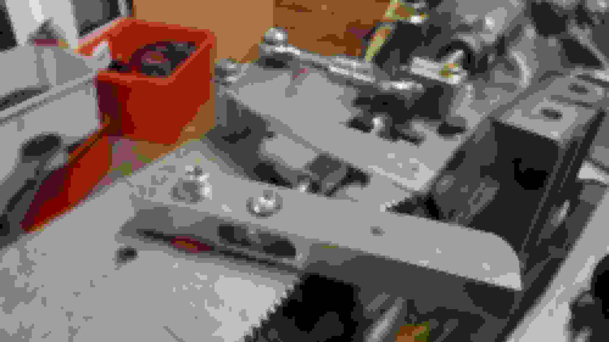
First off I'm going to use two potentiometers to measure the movement of the shift selector. I've got one working as a test and it's accurate to around 0.5mm of movement on the lever arm which should be fine for measuring if the selector made the gear change. These potentiometers fee to the analog inputs on the arduino which will drive a 16 segment display. It will also feed back to the main logic loop whether or not the shift move was successful.
I have also mocked up the mechanical linkages on the box itself. They need to be made properly yet but they are ok for testing. I'll cnc them my design is done. There is a little bit of rotation genetated from the linkages in the up down direction but Im hoping its small enough to not be an issue.
lastly my pneumatics arrived. They are tiny little cylinders but pack a punch!
If you dont want to do an H to sequential conversion manually, which I think you should do and do it with a cam and drum design.
You should have 1 cylinder that goes in through the back of the trans case and pushes in and out directly on the shift rod/rail. And then have the second cylinder on a lever to rotate the shift rod/rail. Dont mimic the persons hand moving the shifter, mimic what the shifter does to the shift rod.
Do you think you can get finite position control of those actuators with PWM of the solenoid? What pressure are you using to run these? My mind is wandering to other projects.
The shift speed is set low atm. I need to make another metal bracket up for the cylinders rather than using cable ties and then I can try upping the shift speed.
Gear selector mechanism is all mocked up. I've left some extra length on the selector arms for when I set shift length so I can adjust the ratio. Hopefully it all fits.
Cycling through the gears. Each arm moves around 45mm which is what the pneumatics offset.
Now I just need some shift push pull cables and I'll be ready to test.
Looking good. I can't wait to see this on the car, and to hear how it works.
It will be interesting that's for sure. I just need to hope the logic I'm building into the ardiuno is good because one miss shift and I'll be down an engine! Hardware wise I'm fairly happy with everything. All the mechanical linkages are fairly easy, I just need to make sure they are made so they don't wear or catch. I'm ordering some shift cables today so I'll be able to test it all on an actual gearbox soon. The software and logic side still needs lots of work.
I think I have upshifts sorted by using a shift cut input on my ECU, or alternatively just switching the ign relay off. The ardunio will receive a shift up input, cut ignition, fire the pneumatics, check for successful gear change via the poteniometers, then re-engage ign and display successful gear change on the led display... hopefully with a nice loud pop down the exhaust to signal a successful shift.
Down shifts are far harder to automate, so for now I'll still need to dab the clutch to unload the dogs, whilst blipping the throttle and hitting the gear down button. How that will all work I'm not so sure but I can really only test it on the track. I'm going to use a CAN shield on the arduino to receive RPM input from the ECU and do a calc on each downshift to make sure I'm not exceeding my rev limiter on the following gear. I think that's the biggest risk to my engine as there is no way to stop an over-rev once I tap that button. I think the pneumatics will be strong enough to rip it out of gear and ram it into another so if I tap that button at the wrong time it could be disastrous. I'm not sure what I'll do but it will probably abort the gear change and wait for another gear down input.
Last night I cranked down the shift delay between the 3 step (eg 2nd to 3rd) shifts. I can get them firing super fast, so fast it sounds like a single move but then there is no drag at all on the cylinders. Once I hook the box up it will most likely slow down a bit.
Don't interrupt power to the coils. If you have just started charging a coil to fire, and then you cut power, it will immediately fire the cylinder with some amount of advance more than it would have if it fully charged the coil to the amount specified in the dwell settings.. Better to tell the ecu to cut all future events, but not any that are currently happening.
I would write the software to measure RPM in 2 different ways, or write it such that it can detect an error if it happens, and if so disable all shifting or at least disable downshifting.
I would also have a clutch actuator so you can just drive it with paddles. I assume you're doing all this work to make the car faster/more consistent, and having the clutch also controlled would make the system work a lot better. A
About 6 or 7 years ago I built a similar system to what you're doing for a FSAE car. My system only needed 1 actuator since it was already a sequential trans. What worked best on our car was, if user says shift, cut spark, wait X time, then turn on actuator for Y time, then enable spark and turn off actuator. It gave the system a delay I could adjust to get the current gear out of a bind and the motor shut off, and a time to shift I could adjust separately. We ended up settling on 50ms total shift times. Although the actuators were faster, 50ms was bomb proof even at lower than normal CO2 pressures. It worked at 40ms, and at 30ms it worked most of the time but sometimes missed.
I wanna see you do the clutch too, because if I ever did what you're doing, I would 100% make the clutch automated as well.
Is it easier to reliably shift your trans from gear to gear when racing vs a syncro box? I assume it is.
With the clutch activation, I'll still need the manual clutch for launching / stopping. If I did it hydraulically I would need to set it up with a parrallel master driven by pneumatics feeding into a tee. But then if I hit the gear down button whilst my foot is on the clutch it will either damage the slave / pressure plate or push my foot back. I could have a clutch switch so that the clutch pneumatics don't fire if my foot is on the clutch.
I could also do it mechanically so that either the pneumatics or the clutch pedal pushes onto the master.
I think first stage is just replacing the manual gear selection. Second stage is optimising it for speed.
Currently shifts are very fast when I'm confident.... but due to the layout of the box with 1st in 5th position I'm a bit tentative going from 3rd to 4th especially whilst cornering. I know if I hit that 3rd gate by mistake its all bad.

 05-06-2017, 03:13 PM


 0
0