Upgrading to Coil on Plugs (all years) COP writeup
 09-18-2007, 11:15 AM
#1
Boost Czar


Thread Starter
iTrader: (62)
Join Date: May 2005
Location: Chantilly, VA
Posts: 79,490
Total Cats: 4,079
Installing COPs
original discussion here: https://www.miataturbo.net/forum/t4756/
Parts required:
Set of Toyota 1ZZ-FE 1.8L 2000+ Coils $50-75 (many others work)
90080-19015
90919-02239
90080-19023
90919-02234
Optional Part Required:
Spare ignitor (1.6L only)
1K resistor (Standalone ECU installs only - jump IG- to B+ in the diagnostics box if you have no tach in your gauge cluster)
10,000uF capacitor (install on 12v and GND)
.070-.110" spades for connection to coils
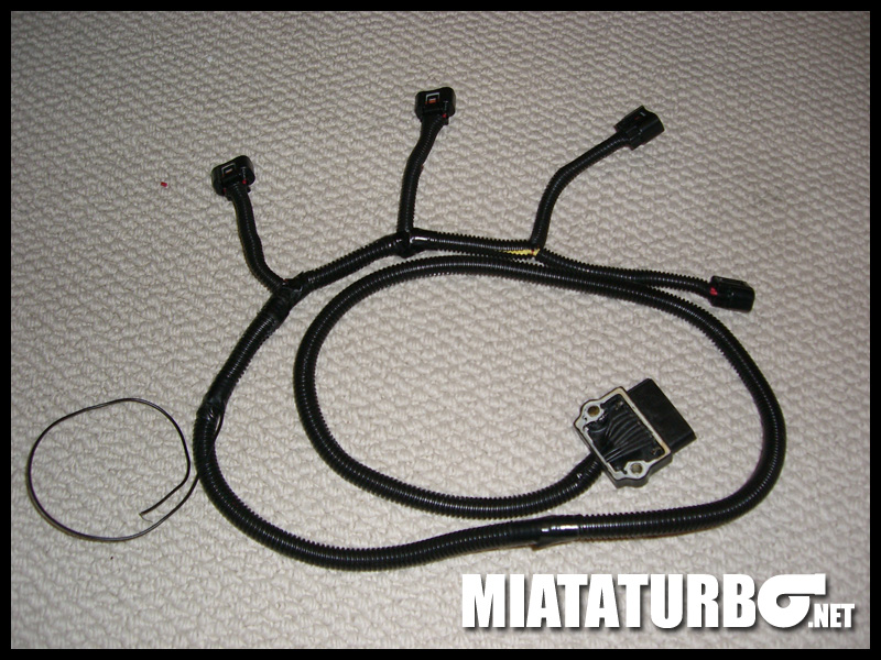
Genuine Coil Connectors with wires cut from harness
DIY Toyota Coil connectors & Contacts $30
Wires, solder, snipers, etc.
Aftermarket ECU owners:
dwell these at 3.5ms cranking, 2.5ms at 12v
Wiring Diagrams:
by: Lazzer408
This is pretty self explainatory
1.6L Schematics:
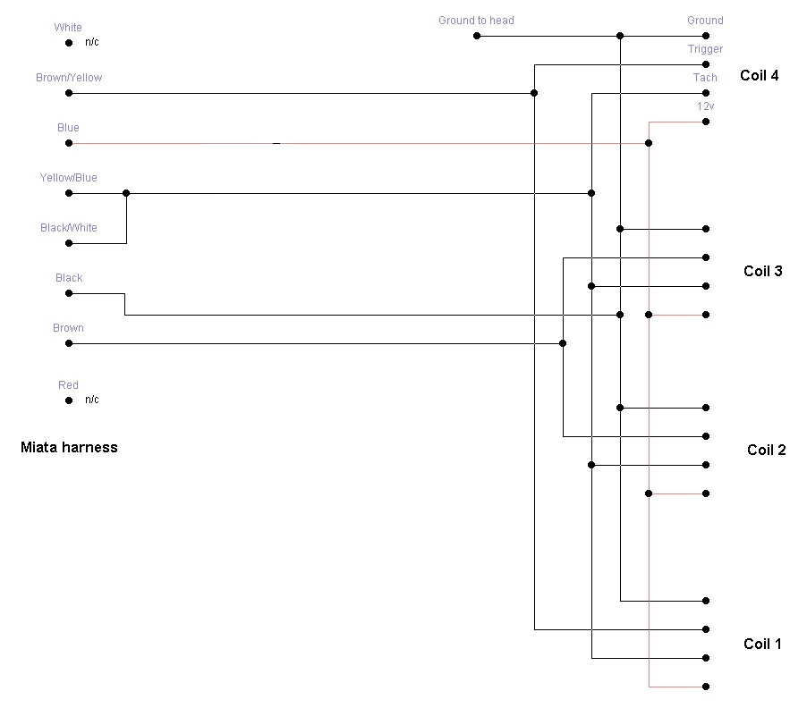
1.8L 94-95 Schematics

1.8L '95.5+ Schematics
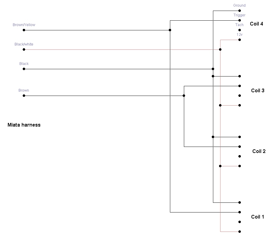
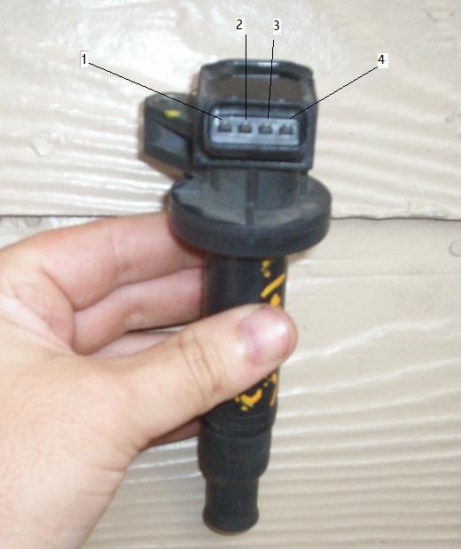
1 ground
2 trigger
3 tach
4 +12V
Proceedure:
1.6L only: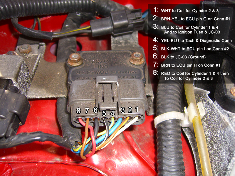
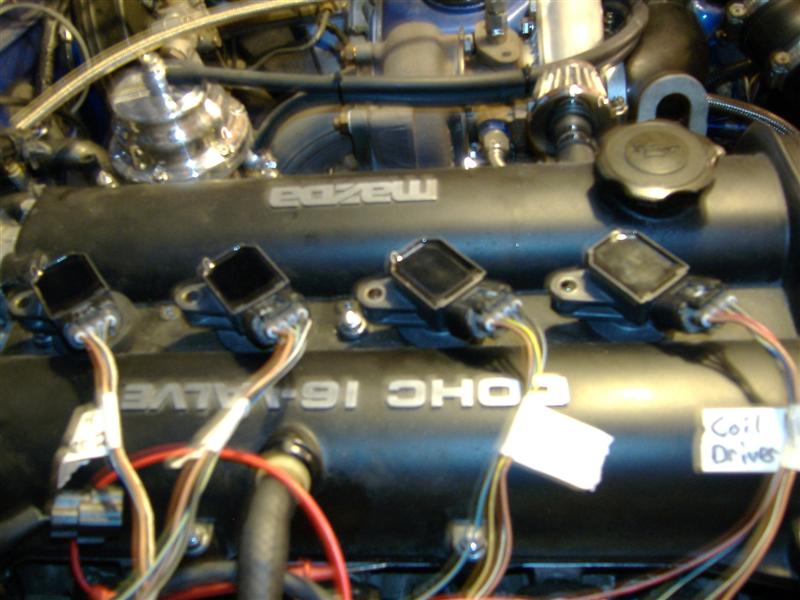
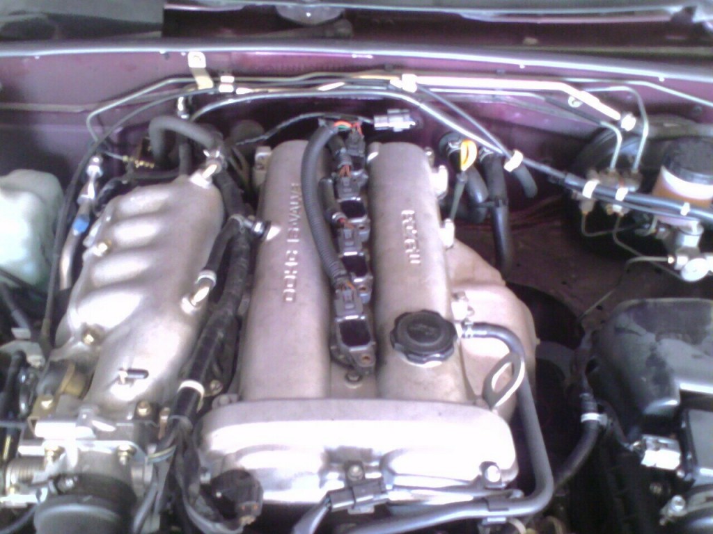
The rest is easy. make a harness to length according to the diagrams. 1.8Ls have ignitors directly on the coil packs, so use the wiring from there. That's it. simple simple.
The plugs will vibrate up off the valve cover if you don't fasten them to it. You can still drive the car, but doing so for an extended period of time will cause some problems. This parts up to you how you'd like to do it.
Examples:
original discussion here: https://www.miataturbo.net/forum/t4756/
Parts required:
Set of Toyota 1ZZ-FE 1.8L 2000+ Coils $50-75 (many others work)
90080-19015
90919-02239
90080-19023
90919-02234
Optional Part Required:
Spare ignitor (1.6L only)
1K resistor (Standalone ECU installs only - jump IG- to B+ in the diagnostics box if you have no tach in your gauge cluster)
10,000uF capacitor (install on 12v and GND)
.070-.110" spades for connection to coils
Genuine Coil Connectors with wires cut from harness
DIY Toyota Coil connectors & Contacts $30
Toyota P/N 90980-11885 for the coil connector
www.partznet.com (Housing Only)
Housing only, housing with terminals, housing with terminals and pigtails:
Ballenger Motorsports
www.spoolinup.com
Housing only, housing with terminals, housing with terminals and pigtails:
Ballenger Motorsports
www.spoolinup.com
If you choose to crimp your own pigtail, this is the proper tool:
http://www.bmotorsports.com/shop/pro...roducts_id/364
Tools Required:http://www.bmotorsports.com/shop/pro...roducts_id/364
Wires, solder, snipers, etc.
Aftermarket ECU owners:
dwell these at 3.5ms cranking, 2.5ms at 12v
Wiring Diagrams:
by: Lazzer408
This is pretty self explainatory
1.6L Schematics:
1.8L 94-95 Schematics
1.8L '95.5+ Schematics
1 ground
2 trigger
3 tach
4 +12V
Proceedure:
1.6L only:
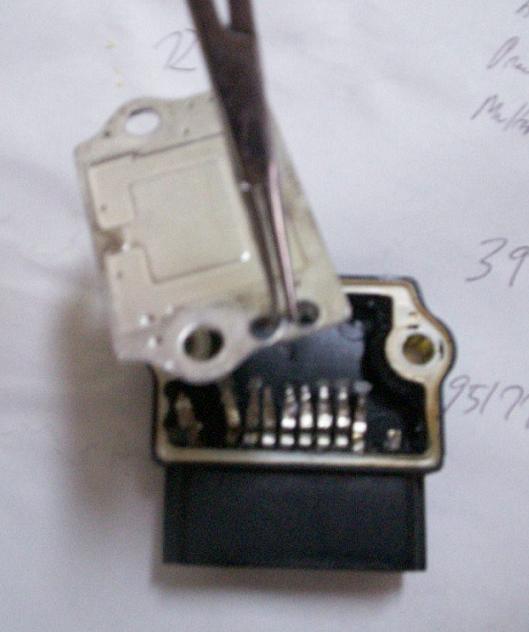
two options for wiring the coils from the start. 1. cut your ignitor connector and wire straight from there. 2. open your ignitor up and wire directly off the pins for a PnP solution.
1.
2.
Flip ignitor over, top side down. Drill 2 small holes near edge. Holes look like a big spider bite.
Insert small pliers (I used a surgical hemostat) into holes and clamp. Slowly pull metal bottom plate away from the plastic body. It is simply siliconed in place and will come free.
Carefully break the solder joints between the terminal pins and circuit board.
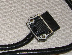
Drill a hole at the rear end of the ignitor for the wires to pass through, proceed to solder directly onto the pins.
The plugs will vibrate up off the valve cover if you don't fasten them to it. You can still drive the car, but doing so for an extended period of time will cause some problems. This parts up to you how you'd like to do it.
Examples:
Last edited by Braineack; 01-20-2012 at 08:28 AM.

Reply
 7
7

7
09-20-2007, 08:33 PM
#2
Boost Czar
Thread Starter
iTrader: (62)
Join Date: May 2005
Location: Chantilly, VA
Posts: 79,490
Total Cats: 4,079
Ok here's how I mounted mine:
making the plate is extremely simple.
I used 22g alumin. (pretty thin but good for the job) got a sheet for $3.99
4 nuts and bolts m6x40
1" hole saw
ruler

I didn't take precise measurements, but that shows you what to do.
1. Put a bit grease on each of the three valve cover bolt holes and lay the 1.5"x15" strip down. This marks the positon of each to drill out.
2. Once drilled, measure from each hole made for the spark plug holes. Very simple, something like 1.25" away center to center. Mark each spot on your strip and drill with the hole saw.
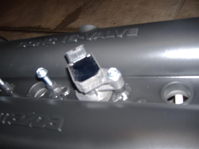
3. Once done, lay the strip back down on the valve cover. Inser thte COPs into the holes. Spin however you want them facing. Mark the position of the tabs with a pencil or drillbit or something. Drill.
4. Finished. Insert the M6 bol up through the mounting holes from underneath. Bolt the strip down with the valve cover bolts. Insert the COPs into the holes and onto the bolts. Insert the nuts and tighten. The end.

don't laugh at that drawing.
here are my final results:


making the plate is extremely simple.
I used 22g alumin. (pretty thin but good for the job) got a sheet for $3.99
4 nuts and bolts m6x40
1" hole saw
ruler
I didn't take precise measurements, but that shows you what to do.
1. Put a bit grease on each of the three valve cover bolt holes and lay the 1.5"x15" strip down. This marks the positon of each to drill out.
2. Once drilled, measure from each hole made for the spark plug holes. Very simple, something like 1.25" away center to center. Mark each spot on your strip and drill with the hole saw.
3. Once done, lay the strip back down on the valve cover. Inser thte COPs into the holes. Spin however you want them facing. Mark the position of the tabs with a pencil or drillbit or something. Drill.
4. Finished. Insert the M6 bol up through the mounting holes from underneath. Bolt the strip down with the valve cover bolts. Insert the COPs into the holes and onto the bolts. Insert the nuts and tighten. The end.
don't laugh at that drawing.
here are my final results:
Last edited by Braineack; 12-21-2007 at 10:58 AM.
Reply
3
3
03-02-2011, 10:48 AM
#3
Boost Czar
Thread Starter
iTrader: (62)
Join Date: May 2005
Location: Chantilly, VA
Posts: 79,490
Total Cats: 4,079
I've added a better source for the connectors to the writeup above. There you can buy connectors with pigtails already ready, or a kit with the proper terminals/weather seals, or just the housings. They also have the proper tool for crimping these terminals.
Reply
0
0
11-11-2014, 01:37 PM
#5
Moderator

iTrader: (12)
Join Date: Nov 2008
Location: Tampa, Florida
Posts: 20,646
Total Cats: 3,009
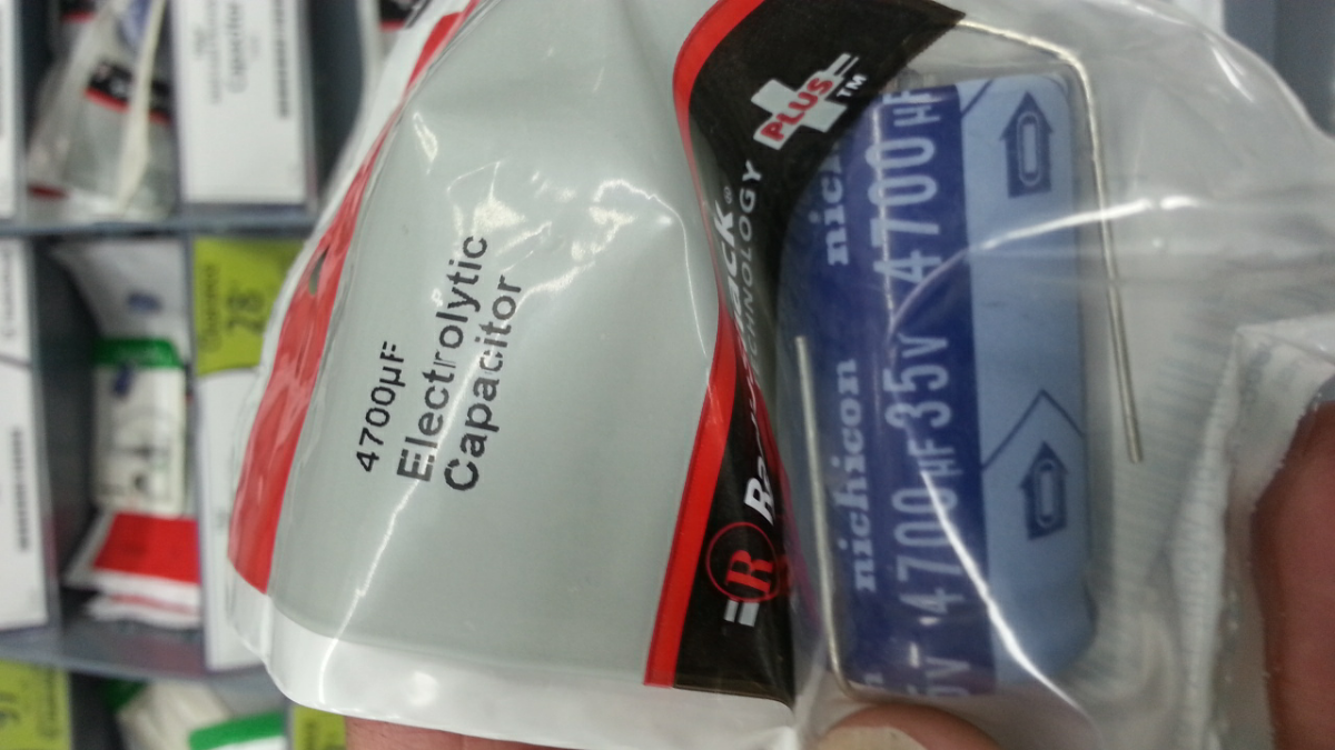
Having never purchased a capacitor or resistor from a store in my life, where would one go locally for such an item? Radio Shack? I'm sure I could buy one online somewhere but...how do I know it is the right item?
Another Example: LS2 Coils
The LS2 coil-near-plug coils are similar in form and function to the LS1 coils described above. This 'family' of coils includes:
We will call the second coil type the LS2/truck coil. These two types of coil have the same connector and pin-out, but the physical mounting pattern is different. The coil connector (GM# 12580353) can be found as:
The LS2 coil has 4 connections (as well as the high tension terminal for the spark plug wire, of course):
 The two capacitors are optional but recommended. The 1.0 �F capacitor on the +12V is helpful, it is similar to the one used on EDIS. What it does is provide brief energy storage for the discharge. The other capacitor will help eliminate back-fed noise to the MegaSquirt controller. Use a 100 pF to 0.001 �F cap on the TTL trigger input wire to ground. What this does is shunt extremely fast noise spikes to ground and not let them feed back to the MegaSquirt processor. The added capacitance is minimal - with the series resistance of 1,000 ohms (in the controller) and a 100 pF capacitor the RC 3dB time constant is 2πR � C = 0.6 microseconds.
The LS2 built in coil igniters (the amplifier that drives the coil's primary current based on the sequencer signal) will follow the sequencer signal pulse width. When the signal from the sequencer is high (3 to 5+ Volts - with very little current from the controller, a few dozen milliAmps), the coil current will be building. When the signal from the sequencer is pulled low (shut off), the coil will spark. The duration of the signal from the sequencer determines the dwell (though the coil igniter limits this to no more than ~8 milliseconds).
The maximum dwell should be set at 4.5 milliseconds - going longer does not generate any more spark energy.
To get 4.0 milliseconds of running dwell, the nominal dwell parameters should be set to:
Maximum Dwell
4.5 milliseconds
Maximum Spark Duration
2.0 milliseconds
Acceleration Compensation
0.5 milliseconds
Battery Voltage Compensation
SettingNet VoltageDwell Compensation
-3.0 8.0 Volts 2.4 milliseconds
-1.010.0 Volts 0.9 milliseconds
0.012.0 Volts 0.0 milliseconds
0.514.0 Volts-0.5 milliseconds
1.016.0 Volts-0.9 milliseconds
This will give 4.5 - 0.5 = 4.0 milliseconds at 14.0 volts while running with the alternator charging normally. There is lots more information on setting dwell here: Setting Dwell.
Here is a video of the coil in action - with the LS1 on the test stand you can hear the sparking, not loud but certainly audible. With the LS2/truck coil it sounds like someone is banging on the table!
The LS2 coil-near-plug coils are similar in form and function to the LS1 coils described above. This 'family' of coils includes:
- the LS2 coil (GM# 12573190, AC Delco D514-A) from the 2005-2006 Corvette (& GTO and Avalanche), and
- the GM coil used on 2002-2005 Cadillac Escalade, 2000-2006 Yukon, 1999-2006 Chevy Silverado, 2001-2005 Trail Blazer, and some Hummers, etc.. The model is GM# 10457730 or AC Delco D585 (also Wells C1251, Standard UF262, GM/Daewoo 190005218). The LS2/truck coil has a visible external aluminum heat sink near the connector.
We will call the second coil type the LS2/truck coil. These two types of coil have the same connector and pin-out, but the physical mounting pattern is different. The coil connector (GM# 12580353) can be found as:
- Coil Connector Pigtail - small (D581) at www.roblinstores.com, or
- Delphi number: 15439568, which you can order as Mouser 829-15439568
The LS2 coil has 4 connections (as well as the high tension terminal for the spark plug wire, of course):
- A = Coil Primary Ground
- B = Ignition low noise ground from ECU (ground)
- C = Ignition digital signal from ECU (+5V)
- D = +12V Supply to Coil Primary
The LS2 built in coil igniters (the amplifier that drives the coil's primary current based on the sequencer signal) will follow the sequencer signal pulse width. When the signal from the sequencer is high (3 to 5+ Volts - with very little current from the controller, a few dozen milliAmps), the coil current will be building. When the signal from the sequencer is pulled low (shut off), the coil will spark. The duration of the signal from the sequencer determines the dwell (though the coil igniter limits this to no more than ~8 milliseconds).
The maximum dwell should be set at 4.5 milliseconds - going longer does not generate any more spark energy.
To get 4.0 milliseconds of running dwell, the nominal dwell parameters should be set to:
Maximum Dwell
4.5 milliseconds
Maximum Spark Duration
2.0 milliseconds
Acceleration Compensation
0.5 milliseconds
Battery Voltage Compensation
SettingNet VoltageDwell Compensation
-3.0 8.0 Volts 2.4 milliseconds
-1.010.0 Volts 0.9 milliseconds
0.012.0 Volts 0.0 milliseconds
0.514.0 Volts-0.5 milliseconds
1.016.0 Volts-0.9 milliseconds
This will give 4.5 - 0.5 = 4.0 milliseconds at 14.0 volts while running with the alternator charging normally. There is lots more information on setting dwell here: Setting Dwell.
Here is a video of the coil in action - with the LS1 on the test stand you can hear the sparking, not loud but certainly audible. With the LS2/truck coil it sounds like someone is banging on the table!
Last edited by sixshooter; 11-11-2014 at 03:23 PM.
Reply
0
0

 11-12-2014, 04:10 PM
#13
Moderator
iTrader: (12)
Join Date: Nov 2008
Location: Tampa, Florida
Posts: 20,646
Total Cats: 3,009
I found a good seller on ebay who is actually local to me (go figure). His ebay name is SemiSurplus. He's got boatloads of this stuff in a warehouse nearby and I'm going to stop by in the morning. I talked to him on the phone and he is really easy to deal with. Thanks guys.
Reply
0
0

 11-13-2014, 02:35 PM
#18
Elite Member
iTrader: (10)
Join Date: Jun 2006
Location: Athens, Greece
Posts: 5,976
Total Cats: 355
I've never installed a capacitor in any of the cars I've installed Toyota COPs, and I never had an issue. The Toyota COPs will work fine right up to 26-27psi, and that's that. Installing a capacitor won't help. Do the Toyota donor cars even have one?
Reply
0
0
11-14-2014, 12:02 AM
#20
I've used the Nology wires with built-in capacitors and they noticeably better than any other plug wire I've used. Funny, plug wires aren't all the same.
I'd like to find out just how big those capacitors are. I've got a set in my garage, and just need to figure out how to test them.
I'd like to find out just how big those capacitors are. I've got a set in my garage, and just need to figure out how to test them.
Last edited by cordycord; 11-14-2014 at 12:40 AM.
Reply
0
0


