Bryce does the VVTeez
 03-22-2012, 02:55 AM
#141
Cpt. Slow

iTrader: (25)
Join Date: Oct 2005
Location: Oregon City, OR
Posts: 14,192
Total Cats: 1,135
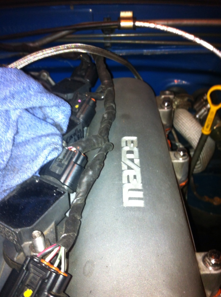
Try this stuff on the wiring:
http://vanguardwholesale.amazonwebst...B00004WLKT.htm
I used it on my COPs harness and it's been sitting on the valve cover for 3 track days so far and is still looking bauce. Protects better than plastic and looks much better too.
http://vanguardwholesale.amazonwebst...B00004WLKT.htm
I used it on my COPs harness and it's been sitting on the valve cover for 3 track days so far and is still looking bauce. Protects better than plastic and looks much better too.

Reply
 0
0

0
03-23-2012, 12:52 AM
#142
Elite Member
Thread Starter
iTrader: (24)

Join Date: Jul 2007
Location: Cypress, TX
Posts: 3,759
Total Cats: 35
I figured out the idle spike. I had the PWM adder for the idle up feature when the fans come on set to 10%. My working PWM range is from 65% to 80% at 383 hz.
Got any pictures of the finished product? I was just going to be lazy/standard and throw some corrugated tubing on the wiring.
Try this stuff on the wiring:
http://vanguardwholesale.amazonwebst...B00004WLKT.htm
I used it on my COPs harness and it's been sitting on the valve cover for 3 track days so far and is still looking bauce. Protects better than plastic and looks much better too.
http://vanguardwholesale.amazonwebst...B00004WLKT.htm
I used it on my COPs harness and it's been sitting on the valve cover for 3 track days so far and is still looking bauce. Protects better than plastic and looks much better too.

Reply
0
0
 03-26-2012, 04:08 AM
#144
Elite Member
Thread Starter
iTrader: (24)
Join Date: Jul 2007
Location: Cypress, TX
Posts: 3,759
Total Cats: 35
I think I'll do that, then cover it with corrugated tubing. I don't know if I like the idea of it hardening, but maybe that's better than electrical tape becoming a sticky mess after some period of time.
I've been driving the car around and to the GF's house (5 minute drive- Take that, Hustler!) running on the NB sensors. No matter what I did with pot R11, I would still get sync loss most of the time above 4k rpms.
I routed the CMP wire back to the mainboard, utilizing Abe's circuit. It was late by the time I finished, but the car revved nicely to 7400 RPM.
Yesterday, I set off on a journey into town to meet up with a fellow Miata owner. When I got on the highway with the car up to temp, I started getting that familiar 'harder than a rev limiter' bucking that I have now associated with a temporary sync loss. After 5 minutes on the highway at 3800 rpms, I decided to head back home and take another car. On the way home, I was getting sync loss as low as 2800 rpm.
I took a log and the sync loss reason was #32: No cam signal. I figured out the sync loss is basically only happening when the car is hot. When cranking for a hot restart, it will alternate between synced and unsynced every 3/4 second.
I am thinking the sync loss is due to excessive noise because the CMP signal wires are within 2 inches of 2 of my ignition coil wirings. What confuses me is why the car runs nicely until it gets hot, at which point it starts 'losing' cam signal above 4k rpms.
There's a laptop-powered 2 channel O-scope on craigslist for 60$ that I'm about to buy. I feel that it would prove very useful in troubleshooting this issue.
I installed 1N4001 diodes at the idle valve and VVT solenoid. It bumped my regular idle duty cycle down to ~33%. MUCH better than 73%. The MS3X flyback ciruit design seems to be flawed.
Tomorrow, I'm going to start messing with the VVT control!
Reply
0
0
03-26-2012, 10:46 AM
#145
Elite Member
iTrader: (2)

Join Date: Jan 2007
Location: Los Angeles, CA
Posts: 8,682
Total Cats: 130
No.
Use self sealing silicone tape like curls suggested. You don't need the stupid plastic loop unless it's gonna chafe somewhere.
Only addition to his recommendation is put a zip tie where the ends of the tape are.
Use self sealing silicone tape like curls suggested. You don't need the stupid plastic loop unless it's gonna chafe somewhere.
Only addition to his recommendation is put a zip tie where the ends of the tape are.
Reply
0
0
03-26-2012, 11:22 AM
#146
Cpt. Slow
iTrader: (25)
Join Date: Oct 2005
Location: Oregon City, OR
Posts: 14,192
Total Cats: 1,135
Yeah, I think I did that on the end. The coil plugs pictures are fully wrapped, without a little tag exposed so I figured the zip tie isn't needed.
And I also agree about the plastic ----. It's ugly, stupid, and a sign of poor craftsmanship. Get it off the car.
The silicone tape ---- is really ****. It can be used to seal holes in exhaust pipe for Hustler's sake. And it's a crazy good electrical insulator. Forget the specs on that part.
And I also agree about the plastic ----. It's ugly, stupid, and a sign of poor craftsmanship. Get it off the car.
The silicone tape ---- is really ****. It can be used to seal holes in exhaust pipe for Hustler's sake. And it's a crazy good electrical insulator. Forget the specs on that part.
Reply
0
0
03-27-2012, 02:55 AM
#147
Elite Member
Thread Starter
iTrader: (24)
Join Date: Jul 2007
Location: Cypress, TX
Posts: 3,759
Total Cats: 35
I'm going to put silicone tape on my piston tops to increase compression.
I slightly modified the input circuit based on a revised version of Franks implementation. It seems a little bit better. Desync happens at 5k+rpms, and only when the car is fully up to temperature. Once warm, it even alternates sync/desync while cranking. Reasons are 31 and 32 still.
I bought the O-scope. Gotta figure out how to use it and hook it up tomorrow. I'm wondering if my CPS sensor is bad. The gap doesn't seem to be adjustable. I'm going to Matt's Miata swap meet on Saturday. Might try swapping with somebody to see if the problem goes away.
Scoping the cam circuit should tell a story... Hopefully.
I enabled the VVT output, but for some reason, the VVTAngle gauge is jumping all over the place, even at 0% duty cycle.
Reply
0
0
03-27-2012, 06:18 PM
#148
Elite Member
Thread Starter
iTrader: (24)
Join Date: Jul 2007
Location: Cypress, TX
Posts: 3,759
Total Cats: 35
I have sorted the desync issue. I found a revised version of Frank's input and used it. A couple small changes, but it probably would work without the revision. Here
I soldered in some leads at the input and outputs of the input circuits (lol) so I could scope them on the car. I don't have a stimulator.
Inputs and outputs look good to me.
All this time I have been concentrating on the cam position sensing being the problem. Today I ran a sync error log, and it showed the crank sensor was missing a tooth on desync. I took a peek at the gap on the crank sensor and WOW! The gap was as large as possible within the adjustment range, ~1/4". I closed the gap to credit-card thickness. Tried to start it, but it wouldn't sync. I switched the trigger from rising edge to falling edge. Perfect sync! Fired right up, AND the VVTangle gauge makes sense.
I reset the timing and took the car out for a spin. VVT angle is now holding at 0 degrees. On the test drive, the car felt very sluggish and backfired every time I shifted. Then I remembered I forgot to change the timing back to table after setting the timing. So I was running at 10 degrees. Lol!
Once I set the timing back to table, The car pulls nicely. I'm plugging in numbers on the VVT target table and we'll see how it does once I get the intake cam turning.
Long story short: Crank sensor gap was too large. Set trigger to falling edge instead of rising edge. Why MS gave me errors for the cam sensor? I don't know. Its time to play with VVT.
Reply
0
0
04-09-2012, 08:34 PM
#149
Elite Member
Thread Starter
iTrader: (24)
Join Date: Jul 2007
Location: Cypress, TX
Posts: 3,759
Total Cats: 35
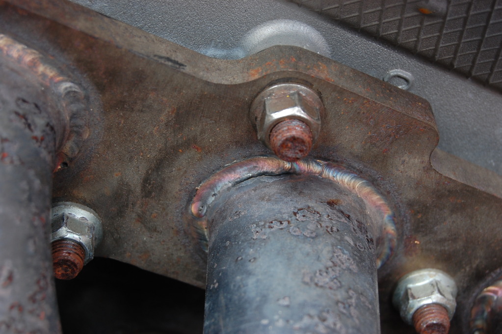
I found a crack on my ebay exhaust manifold.
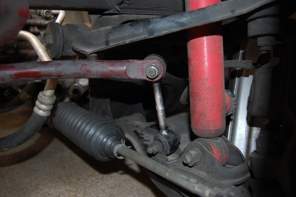
Picked up an MSM front sway bar at Matt's swap meet along with some adjustable end links. When I went to install it, I found out the end links are for an NB and will not work unless I had NB LCAs. I cut, rotated, and welded my stock end links. It was actually very easy. Body roll has been reduced drastically.
I'll have a job during summer and will be able to acquire the rest of the parts needed to go turbo and finish building the 2 liter. Hustler's hypermiler thread has me interested in utilizing the EGR valve with megasquirt to improve fuel economy and let me pass emissions with ease. I barely passed with the 2 liter a year ago.
I'm currently doing some research on the internal workings of the EGR valve. Hopefully I'll just be able to wire it with an on-off output. The NA and NB valves are almost the same physically and look like they would be interchangeable. They have a 6 conductor plug.
The EGR pipe to the manifold will need some work too. I only have an NB2 EGR pipe. I need another EGR pipe to cannibalize in order for it to work with my NA header.
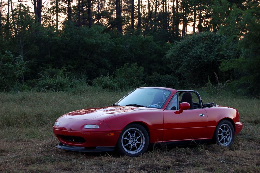
Just took the best picture of my car to date.
Picked up an MSM front sway bar at Matt's swap meet along with some adjustable end links. When I went to install it, I found out the end links are for an NB and will not work unless I had NB LCAs. I cut, rotated, and welded my stock end links. It was actually very easy. Body roll has been reduced drastically.
I'll have a job during summer and will be able to acquire the rest of the parts needed to go turbo and finish building the 2 liter. Hustler's hypermiler thread has me interested in utilizing the EGR valve with megasquirt to improve fuel economy and let me pass emissions with ease. I barely passed with the 2 liter a year ago.
I'm currently doing some research on the internal workings of the EGR valve. Hopefully I'll just be able to wire it with an on-off output. The NA and NB valves are almost the same physically and look like they would be interchangeable. They have a 6 conductor plug.
The EGR pipe to the manifold will need some work too. I only have an NB2 EGR pipe. I need another EGR pipe to cannibalize in order for it to work with my NA header.
Just took the best picture of my car to date.
Reply
0
0
04-10-2012, 04:02 PM
#152
Elite Member
Thread Starter
iTrader: (24)
Join Date: Jul 2007
Location: Cypress, TX
Posts: 3,759
Total Cats: 35
Thanks!
Lol! I bought it used locally and its been good to me. Its of the 'may or may not' hit bellhousing variety. It depends on how you tighten things.
Here's the repair.
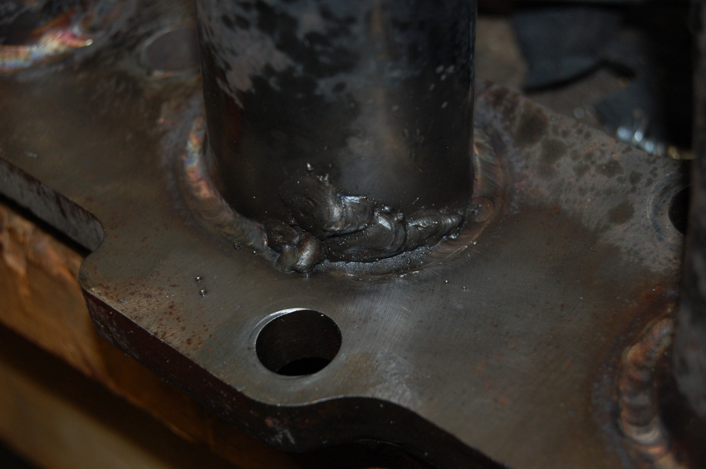
I burnt one giant hole before I realized I was using MS wire instead of SS wire. Switched to SS wire and it filled up just fine. I was going to install my cat, but it was too short, purposed for the 1.6 downpipe setup. Today I'm going to cut the cat out and fit it into my 1.8 testpipe.
Here's the repair.
I burnt one giant hole before I realized I was using MS wire instead of SS wire. Switched to SS wire and it filled up just fine. I was going to install my cat, but it was too short, purposed for the 1.6 downpipe setup. Today I'm going to cut the cat out and fit it into my 1.8 testpipe.
Last edited by Bryce; 04-18-2012 at 12:49 AM.
Reply
0
0
04-18-2012, 12:47 AM
#153
Elite Member
Thread Starter
iTrader: (24)
Join Date: Jul 2007
Location: Cypress, TX
Posts: 3,759
Total Cats: 35
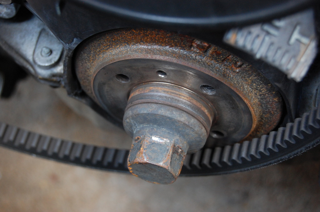
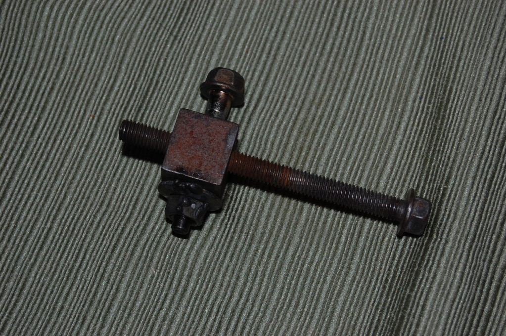
Here's the story about how I almost got to witness my harmonic damper rolling across the street.
I started the car up in the morning last Tuesday and noticed a loud knocking sound. My first thought was "Oh, FML, another spun bearing". Then I noticed the crank pulley was wobbling like crazy.
It was only being held on with 1 out of 4 M6 bolts. And to think I was planning on driving to see the GF an hour away the day before, but didn't.
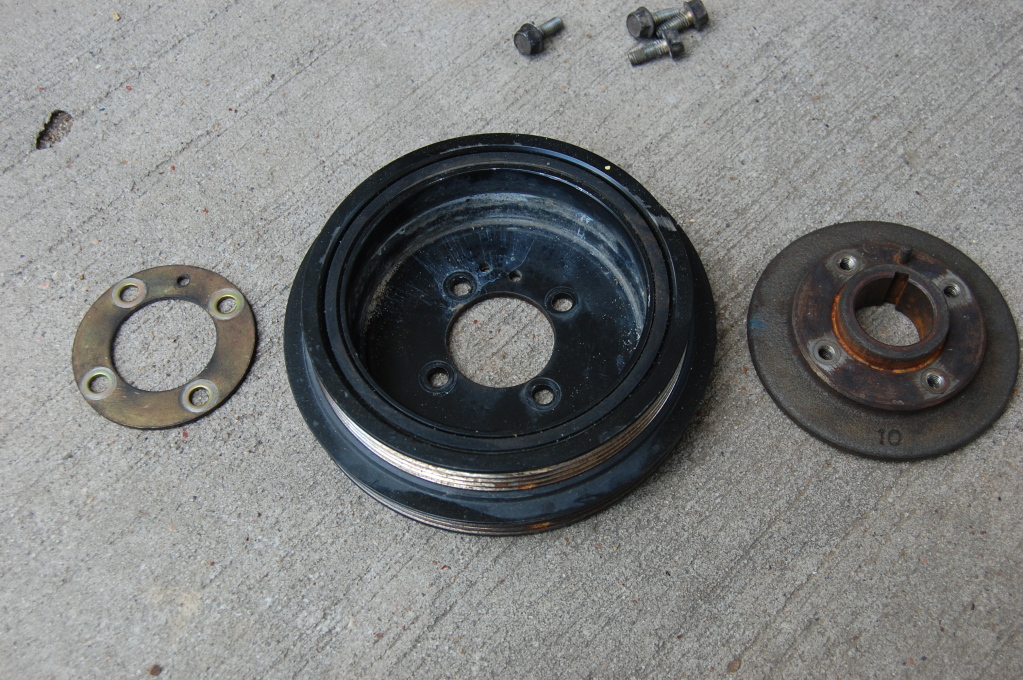
I removed the pulley and discovered the locator pin on the crank pulley boss was missing, which allowed the harmonic damper and timing wheel to rattle back and forth, which loosened the 4 bolts.
When I installed the 04 engine, I had to use my 1.6 harmonic damper because 1.6 cars have a single V belt for the alternator and water pump. 1.8's have a multi V belt. In order to fit the NB crank timing wheel, I used the NB crank pulley boss (89k miles on it) with the 1.6 damper. Why this would happen at 89k miles, I don't know.
Missing locator pin:
Ovaled holes in the harmonic damper and timing wheel:
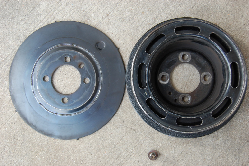
Good ole' V-belt drive:
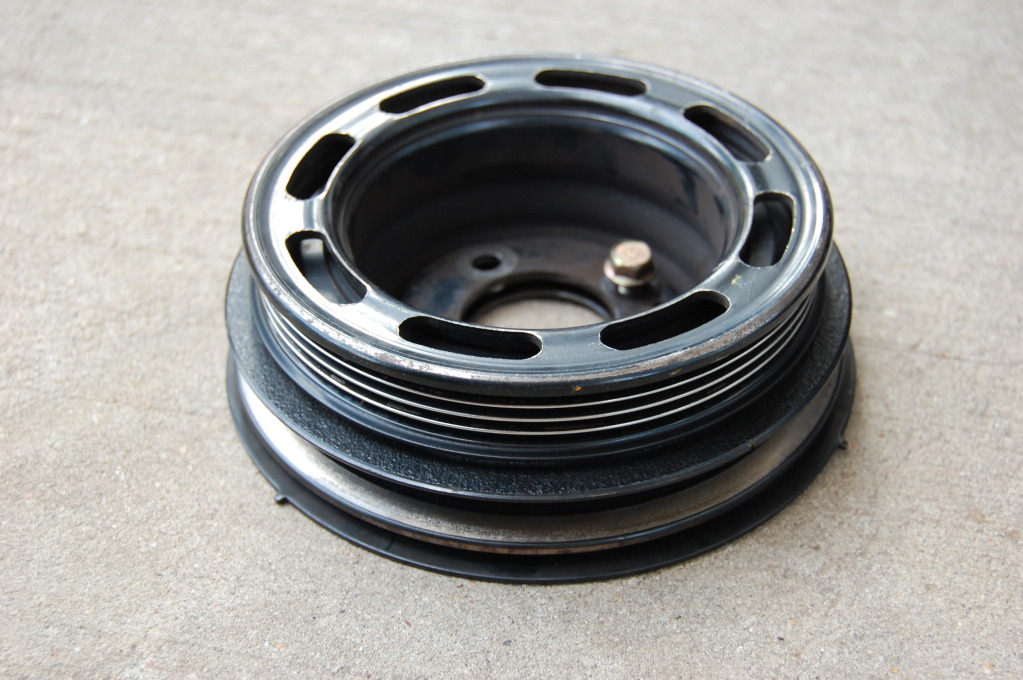
I decided to ditch the 1.6 harmonic damper while I was at it and ordered a 1.8 alternator. IIRC it puts out 5 more amps than the 1.6 alt. I can use all the amps I can get with over 800 watts of sound system power.
There are a few differences between the 1.6 and 1.8 water pump/alternator setups.
1: The front of the 1.8 alternator mount is threaded. 1.6 uses a backing nut. Easy workaround, just screw the mounting bolt in from the back.
2: 1.8 uses a multi V belt. Just use the 1.8 water pump pulley, 1.8 alternator, and appropriate 1.8 harmonic damper setup, and you'll be golden.
3: The 1.8 belt tensioner block is threaded, and the locking bolt is screwed in from the front. On the 1.6, the top mount of the alternator is threaded, and a bolt is screwed in from the rear. Here's my solution:
My new configuration. NB purebred:
The 96-05 crank pulley boss is very difficult to find used. I had to buy mine from Rosenthal.
My Emissions sticker is expired as of this month. I didn't put the header back in and instead installed my stock 1.8 header with the cat. I'm just going to sell the header to a friend. More money for the turbo parts/motor build is a good thing.
I charged the 97 AC system which I bought on here from JustinOMGWTF and have an input and output going to the Expander board to control it. The system is working great! I have basically never had good working AC since I bought the car in 2007.
I picked up an NB dashboard for FREE! That will be going in sometime soon.
I'll likely be starting a full time job after this semester of school that will pay me big bucks. Look forward to more turbo 2 liter progress this summer!
I started the car up in the morning last Tuesday and noticed a loud knocking sound. My first thought was "Oh, FML, another spun bearing". Then I noticed the crank pulley was wobbling like crazy.
It was only being held on with 1 out of 4 M6 bolts. And to think I was planning on driving to see the GF an hour away the day before, but didn't.
I removed the pulley and discovered the locator pin on the crank pulley boss was missing, which allowed the harmonic damper and timing wheel to rattle back and forth, which loosened the 4 bolts.
When I installed the 04 engine, I had to use my 1.6 harmonic damper because 1.6 cars have a single V belt for the alternator and water pump. 1.8's have a multi V belt. In order to fit the NB crank timing wheel, I used the NB crank pulley boss (89k miles on it) with the 1.6 damper. Why this would happen at 89k miles, I don't know.
Missing locator pin:
Ovaled holes in the harmonic damper and timing wheel:
Good ole' V-belt drive:
I decided to ditch the 1.6 harmonic damper while I was at it and ordered a 1.8 alternator. IIRC it puts out 5 more amps than the 1.6 alt. I can use all the amps I can get with over 800 watts of sound system power.
There are a few differences between the 1.6 and 1.8 water pump/alternator setups.
1: The front of the 1.8 alternator mount is threaded. 1.6 uses a backing nut. Easy workaround, just screw the mounting bolt in from the back.
2: 1.8 uses a multi V belt. Just use the 1.8 water pump pulley, 1.8 alternator, and appropriate 1.8 harmonic damper setup, and you'll be golden.
3: The 1.8 belt tensioner block is threaded, and the locking bolt is screwed in from the front. On the 1.6, the top mount of the alternator is threaded, and a bolt is screwed in from the rear. Here's my solution:
My new configuration. NB purebred:
The 96-05 crank pulley boss is very difficult to find used. I had to buy mine from Rosenthal.
My Emissions sticker is expired as of this month. I didn't put the header back in and instead installed my stock 1.8 header with the cat. I'm just going to sell the header to a friend. More money for the turbo parts/motor build is a good thing.
I charged the 97 AC system which I bought on here from JustinOMGWTF and have an input and output going to the Expander board to control it. The system is working great! I have basically never had good working AC since I bought the car in 2007.
I picked up an NB dashboard for FREE! That will be going in sometime soon.
I'll likely be starting a full time job after this semester of school that will pay me big bucks. Look forward to more turbo 2 liter progress this summer!
Reply
0
0
04-18-2012, 08:40 AM
#154
mkturbo.com

iTrader: (24)
Join Date: May 2006
Location: Charleston SC
Posts: 15,177
Total Cats: 1,681
Try this stuff on the wiring:
http://vanguardwholesale.amazonwebst...B00004WLKT.htm
I used it on my COPs harness and it's been sitting on the valve cover for 3 track days so far and is still looking bauce. Protects better than plastic and looks much better too.
http://vanguardwholesale.amazonwebst...B00004WLKT.htm
I used it on my COPs harness and it's been sitting on the valve cover for 3 track days so far and is still looking bauce. Protects better than plastic and looks much better too.
Reply
0
0
04-18-2012, 11:03 AM
#155
Elite Member
iTrader: (2)
Join Date: Jan 2007
Location: Los Angeles, CA
Posts: 8,682
Total Cats: 130
I never knew about self sealing tape before that post Curly. Thanks a lot for cluing me in about it. Unfortunately I did not want to spend $10 a roll on it, so I started searching for a cheaper version. Harbor Freight sells a similar tape for a good bit cheaper. Here is a link to it. I just used some on my car to clean up some wiring. One thing I noticed is that you can not stretch it out to much or it will "come apart" when it rubs against things. I have not actually gone out driving yet since it has been installed, but am planning on doing that sometime in the next few days. I will report back about how it seems to last, but at $3.99 a roll it might be worth you guys checking out.
Reply
0
0
04-18-2012, 11:38 AM
#156
Cpt. Slow
iTrader: (25)
Join Date: Oct 2005
Location: Oregon City, OR
Posts: 14,192
Total Cats: 1,135
Yeah, I've never had that problem. Not sure where you're putting it to cause rubbing, but whatever.
In the miata, I've only put it on my COPs harness, where there isn't much rubbing. The harbor fright stuff definitely looks different, mines is perfectly smooth, no ridges as indicated by the HF pic. It also stretches to like 5x it's "standing" length, working perfectly fine. For me.
This is what I use, only $5 a roll. Search around more, noob.
Reply
0
0
04-18-2012, 11:58 AM
#157
Elite Member
iTrader: (2)
Join Date: Jan 2007
Location: Los Angeles, CA
Posts: 8,682
Total Cats: 130
Yeah, I've never had that problem. Not sure where you're putting it to cause rubbing, but whatever.
In the miata, I've only put it on my COPs harness, where there isn't much rubbing. The harbor fright stuff definitely looks different, mines is perfectly smooth, no ridges as indicated by the HF pic. It also stretches to like 5x it's "standing" length, working perfectly fine. For me.
This is what I use, only $5 a roll. Search around more, noob.
http://www.amazon.com/gp/product/B00...2THMWGWS352ZHK
Yeah. The "right stuff" is VERY hard to rip apart. It is pretty cool. It would probably make for a sick variable volume plenum.
Reply
0
0
04-18-2012, 12:32 PM
#158
mkturbo.com
iTrader: (24)
Join Date: May 2006
Location: Charleston SC
Posts: 15,177
Total Cats: 1,681
Yeah, I've never had that problem. Not sure where you're putting it to cause rubbing, but whatever.
In the miata, I've only put it on my COPs harness, where there isn't much rubbing. The harbor fright stuff definitely looks different, mines is perfectly smooth, no ridges as indicated by the HF pic. It also stretches to like 5x it's "standing" length, working perfectly fine. For me.
This is what I use, only $5 a roll. Search around more, noob.
http://www.amazon.com/gp/product/B00...2THMWGWS352ZHK
In the miata, I've only put it on my COPs harness, where there isn't much rubbing. The harbor fright stuff definitely looks different, mines is perfectly smooth, no ridges as indicated by the HF pic. It also stretches to like 5x it's "standing" length, working perfectly fine. For me.
This is what I use, only $5 a roll. Search around more, noob.
http://www.amazon.com/gp/product/B00...2THMWGWS352ZHK
Reply
0
0
04-19-2012, 03:32 AM
#160
Elite Member
Thread Starter
iTrader: (24)
Join Date: Jul 2007
Location: Cypress, TX
Posts: 3,759
Total Cats: 35
How many feet of tape am I going to need to basically do the entire engine harness?
From firewall main loom, fuel injector subharness, coil harness, and crank/cam sensor harness.
From firewall main loom, fuel injector subharness, coil harness, and crank/cam sensor harness.
Reply
0
0


