Hornetball's Build
 02-18-2011, 11:50 PM
#1
Elite Member
Thread Starter
iTrader: (4)

Join Date: Mar 2008
Location: Granbury, TX
Posts: 6,301
Total Cats: 696
At long last, starting the build.
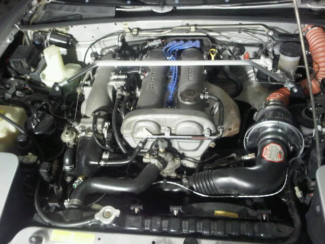
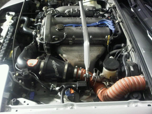
For the past few months, I've been running on a MSPNP with AFM delete, cowl induction and DeatchWerks 350cc injectors. I'm pretty happy with how it's running (those injectors are really smooth). So, now I'm diving into the build. Some before pics:
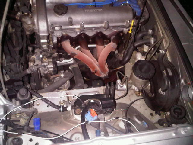
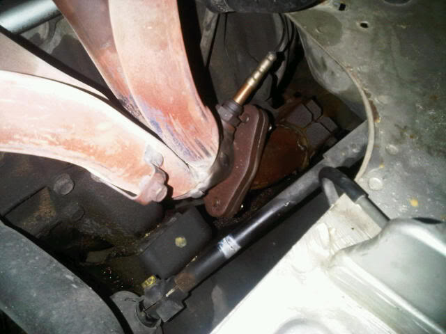
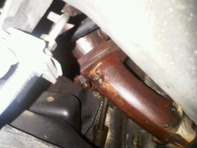
First step was to remove the intake and exhaust. Unfortunately, the exhaust flange ahead of the catalytic converter had been welded over at some point in the car's life. That meant I was stuck dealing with the triangular flange between the exhaust manifold and header pipe. In the end, this worked out OK. I found that there was good access from the driver's side wheelwell to the outer bolts and bracket, and from below (with a long extension) to the inner bolt. Thank God for PB Blaster. Pics:
PB Blaster Soaking
Dreaded Triangular Flange
Wheelwell Access
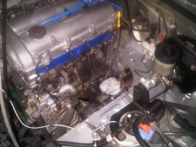
Exhaust Manifold Removed, Side of Engine Cleaned Up.
I'm taking this opportunity to go ahead and refresh all the cooling system rubber. I also cleaned up and painted the structure beneath the brake master cylinder. This seems to be the one area that is frequently corroded on these cars. Since I'm about to expose it to a lot more heat, I felt some Rustoleum was in order.
Next step will be drilling the oil pan. Yikes!
For the past few months, I've been running on a MSPNP with AFM delete, cowl induction and DeatchWerks 350cc injectors. I'm pretty happy with how it's running (those injectors are really smooth). So, now I'm diving into the build. Some before pics:
First step was to remove the intake and exhaust. Unfortunately, the exhaust flange ahead of the catalytic converter had been welded over at some point in the car's life. That meant I was stuck dealing with the triangular flange between the exhaust manifold and header pipe. In the end, this worked out OK. I found that there was good access from the driver's side wheelwell to the outer bolts and bracket, and from below (with a long extension) to the inner bolt. Thank God for PB Blaster. Pics:
PB Blaster Soaking
Dreaded Triangular Flange
Wheelwell Access
Exhaust Manifold Removed, Side of Engine Cleaned Up.
I'm taking this opportunity to go ahead and refresh all the cooling system rubber. I also cleaned up and painted the structure beneath the brake master cylinder. This seems to be the one area that is frequently corroded on these cars. Since I'm about to expose it to a lot more heat, I felt some Rustoleum was in order.
Next step will be drilling the oil pan. Yikes!

Reply
 0
0

0
 02-20-2011, 12:33 AM
#3
Elite Member
Thread Starter
iTrader: (4)
Join Date: Mar 2008
Location: Granbury, TX
Posts: 6,301
Total Cats: 696
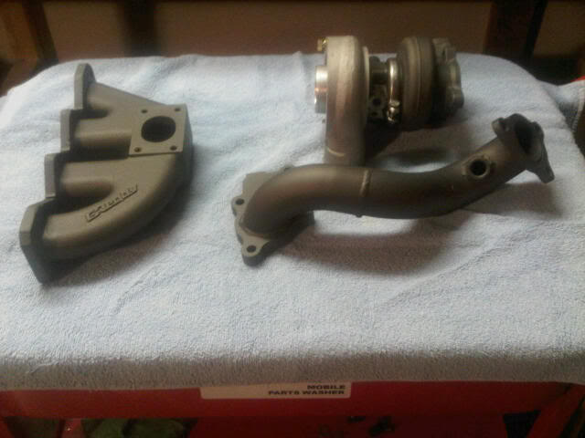
Pretty basic. I've got a Greddy kit, although I'm only planning to use the manifold, turbo and downpipe. Relief cuts have been made and hot parts have been ceramic coated (yeah, I know, lipstick on a pig . . . .). Pics:
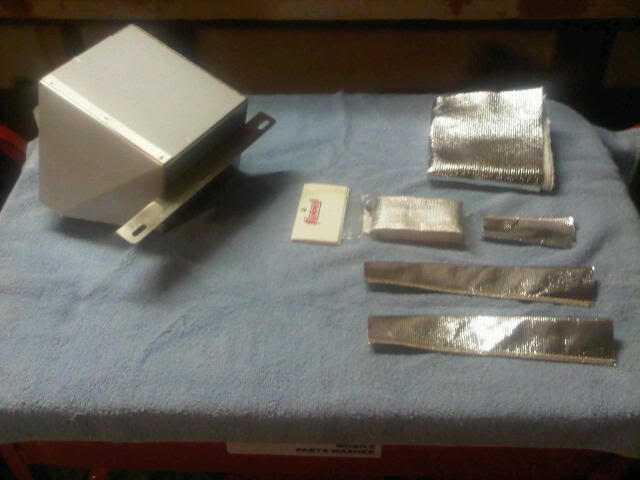
Because I'm ---- about heat, I've got lots of shielding and insulation besides the ceramic coating. The stainless heat shield is from FM and fits great. Other stuff is from Summit. Pics:
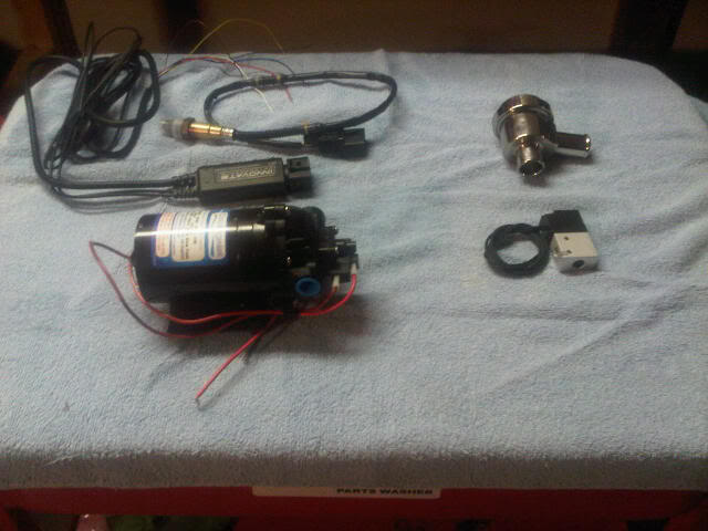
Currently, my MSPNP has been modified for a variable TPS which is fitted to my throttle body. In addition, I'll be pulling the MSPNP to add circuitry and wiring for:
1. LC-1 Wideband
2. Electronic Boost Control
3. Water Injection (have a basic Aquamist kit)
4. Spark Table switching based upon AC clutch power to improve idle with AC (thanks Brain and JP)
Also pictured is a BOV:
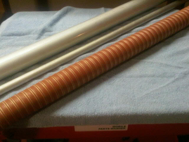
Much of the fabrication work will be on the intake. At this time, I'm planning to only use water injection and no intercooler -- we'll see. The WI nozzle will be mounted immediately post-turbo while the IAT sensor will be just ahead of the throttle plate. The idea is to vaporize as much of the injected water as possible so that the IAT sensor will see its effect as IAT reduction (much like an intercooler). I'm planning to get a dyno tune with WI on and WI off so that I get a sense for how much to reduce ignition advance and boost with increasing IAT. The squirt can be setup to do this automatically. Call it automatic WI flow sensing by looking at what really counts -- IAT reduction. I've got raw materials (6061-T6 for the intake, SCEET for pre-turbo to the cowl induction), a MIG welder and a friend with a beading tool. Should be fun. Pics:
Anyway, that's it for now. Not working on the car this weekend -- I've rented a 30HP Kubota with a loader and box blade to work the property -- a different kind of motorsport. Hopefully, I'll get back at it in the evenings next week.
Because I'm ---- about heat, I've got lots of shielding and insulation besides the ceramic coating. The stainless heat shield is from FM and fits great. Other stuff is from Summit. Pics:
Currently, my MSPNP has been modified for a variable TPS which is fitted to my throttle body. In addition, I'll be pulling the MSPNP to add circuitry and wiring for:
1. LC-1 Wideband
2. Electronic Boost Control
3. Water Injection (have a basic Aquamist kit)
4. Spark Table switching based upon AC clutch power to improve idle with AC (thanks Brain and JP)
Also pictured is a BOV:
Much of the fabrication work will be on the intake. At this time, I'm planning to only use water injection and no intercooler -- we'll see. The WI nozzle will be mounted immediately post-turbo while the IAT sensor will be just ahead of the throttle plate. The idea is to vaporize as much of the injected water as possible so that the IAT sensor will see its effect as IAT reduction (much like an intercooler). I'm planning to get a dyno tune with WI on and WI off so that I get a sense for how much to reduce ignition advance and boost with increasing IAT. The squirt can be setup to do this automatically. Call it automatic WI flow sensing by looking at what really counts -- IAT reduction. I've got raw materials (6061-T6 for the intake, SCEET for pre-turbo to the cowl induction), a MIG welder and a friend with a beading tool. Should be fun. Pics:
Anyway, that's it for now. Not working on the car this weekend -- I've rented a 30HP Kubota with a loader and box blade to work the property -- a different kind of motorsport. Hopefully, I'll get back at it in the evenings next week.
Reply
0
0


 02-20-2011, 08:39 PM
#8
Elite Member
Thread Starter
iTrader: (4)
Join Date: Mar 2008
Location: Granbury, TX
Posts: 6,301
Total Cats: 696
The big plus with the squirt is doing away with the AFM. The torque curve is much smoother without the AFM. 2000-3000 is useable with a NA 1.6. That's quite a change.
As for the Greddy components being old school, well, that's a testament to how long I've had these parts on my shelf. Like I said . . . "at long last."
Thanks for the kind words guys. A little encouragement goes a long way.
Reply
0
0
02-21-2011, 09:07 AM
#11
Elite Member
Thread Starter
iTrader: (4)
Join Date: Mar 2008
Location: Granbury, TX
Posts: 6,301
Total Cats: 696
There is some logic to this order, however. Having WI will let me get my IAT-related spark and boost decay values in one dyno tuning session. Note that these are good values to have whether you cool the intake charge with water or with an intercooler.
One thing to keep in mind with an intercooler is that it doesn't always cool the same. The intercooler's heat transfer mechanism is conduction. Thus, the main things that affect it are air flow and air temperature. It cools less going 25mph in 100�F air than it does going 70mph in 20�F air. So, less effective at the auto-X . . . great. Of course, the big plus is no moving parts -- reliability.
WI cooling (assuming that you aren't spraying so much water that it can't vaporize) will always remove the same amount of heat from the intake charge. The heat is removed by the phase change of the water -- and the heat removal is powerful. However, there are lots of parts here to go wrong.
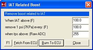
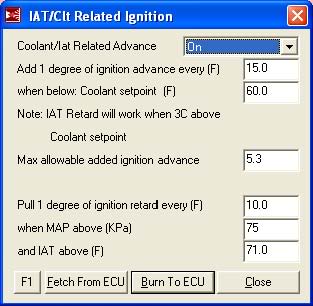
So, in both cases, some engine protection would seem to be in order. What we are protecting the engine against is high intake temperatures. These are the megasquirt areas that are going to give me that protection . . . :
Hey, it's a 182,000 mile short-nose 1.6. The way I see it, perfect for experimenting. I want a rebuild anyway.

Reply
0
0
02-21-2011, 06:04 PM
#13
Elite Member
Thread Starter
iTrader: (4)
Join Date: Mar 2008
Location: Granbury, TX
Posts: 6,301
Total Cats: 696
As for the engine:
1. High mileage (182,000)
2. Good compression
3. Been running synthetic
4. No lifter tick ("sort of" an indication of internal cleanliness)
5. 30K since timing belt and water pump
6. Short nose crank with Loctite fix
Running well at the moment.
Reply
0
0
02-23-2011, 10:34 AM
#14
Elite Member
Thread Starter
iTrader: (4)
Join Date: Mar 2008
Location: Granbury, TX
Posts: 6,301
Total Cats: 696
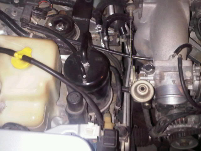
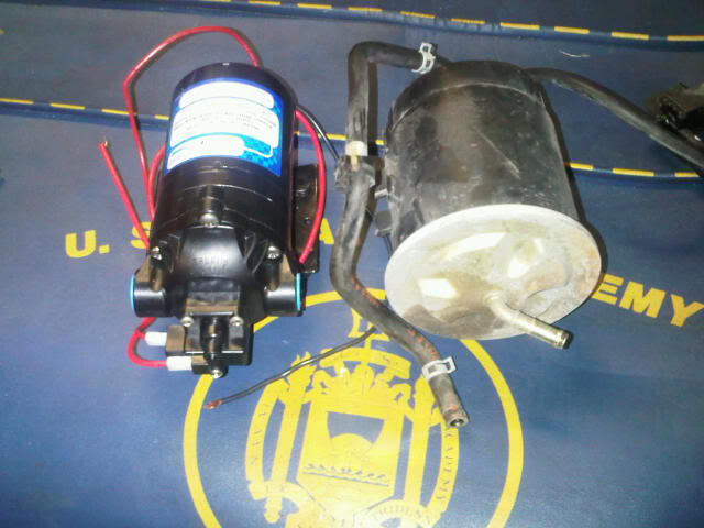
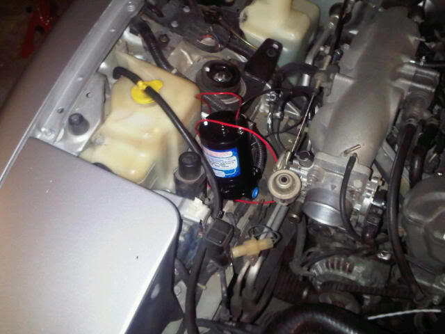
Well, not much progress. Waiting for parts and busy at work. I did do a test fit of the WI pump in the charcoal cannister area. Basic fit was OK, but there are some issues with inlet/outlet ports, etc. I'll need to weld up a bracket for this. Pics:
Also, there is some doubt on my plan to use MS to retard boost for high intake temperatures. For this to work, the MS EBC needs to be closed loop. It seems that no one is running their MSPNP or MS1's with closed loop EBC -- so there is some doubt that this is functional. Anyway, will give it a try. If it doesn't work, then it will be IC time because I really don't trust any other fail safe for WI. Too much to go wrong.
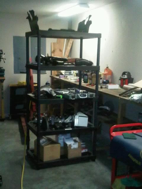
When I started this, my wife had some ventilated shelving in her closet that she wanted to get rid of. So, I moved it into the garage and as I began tearing down, stacked parts on it. This really works well! Keeps table and floor space available and is great for organizing parts and bringing them to eye level. Probably obvious to the rest of you, but I was surprised at what an improvement this made to work conditions.
That's it for now.
Also, there is some doubt on my plan to use MS to retard boost for high intake temperatures. For this to work, the MS EBC needs to be closed loop. It seems that no one is running their MSPNP or MS1's with closed loop EBC -- so there is some doubt that this is functional. Anyway, will give it a try. If it doesn't work, then it will be IC time because I really don't trust any other fail safe for WI. Too much to go wrong.
When I started this, my wife had some ventilated shelving in her closet that she wanted to get rid of. So, I moved it into the garage and as I began tearing down, stacked parts on it. This really works well! Keeps table and floor space available and is great for organizing parts and bringing them to eye level. Probably obvious to the rest of you, but I was surprised at what an improvement this made to work conditions.
That's it for now.
Reply
0
0
02-27-2011, 08:26 PM
#15
Elite Member
Thread Starter
iTrader: (4)
Join Date: Mar 2008
Location: Granbury, TX
Posts: 6,301
Total Cats: 696
Still waiting for parts. However, I was able to make a bit of progress this weekend. Pics:
Replaced all the garbage Greddy hardware. Drilled the new bolts for safety wire.
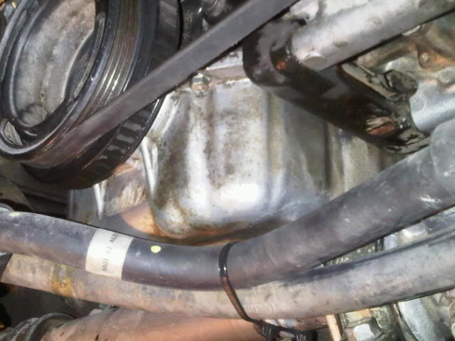
After spending a lot of time on the Hakuna Miata site (great pictures of the inside of the oil pan), it looked like this surface would provide the best protection against touching the pickup and would be easy to drill. AC lines temporarily zip tied out of the way.
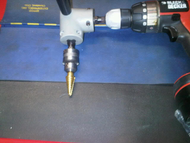
Drilling rig.
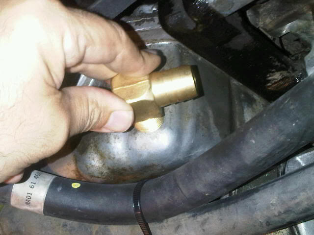
Mockup with 90� fitting.
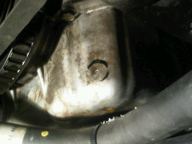
A bit of touchup paint on the fitting marks the spot. Pilot hole drilled.
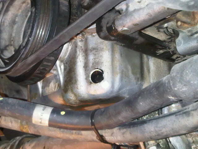
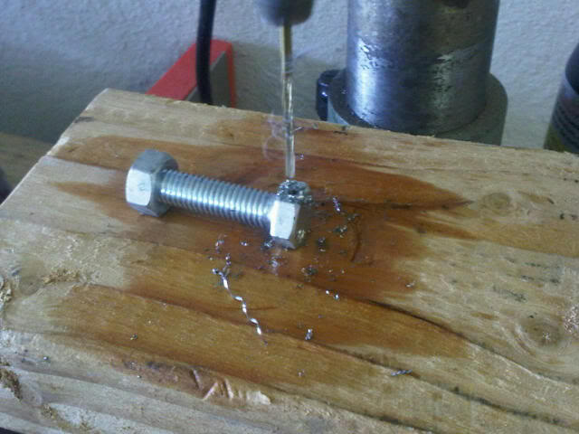
Drilled!! Compressed air on the PCV grommet + grease kept the chips out of the engine. I was able to get a finger into this hole to confirm that there weren't any chips inside. Plenty of clearance to the pickup tube from this angle.
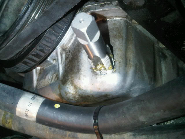
Cutting threads with compressed air and lots of grease. 1/2" NPT.
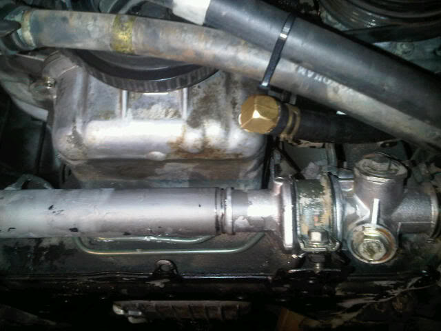
Finished.
Replaced all the garbage Greddy hardware. Drilled the new bolts for safety wire.
After spending a lot of time on the Hakuna Miata site (great pictures of the inside of the oil pan), it looked like this surface would provide the best protection against touching the pickup and would be easy to drill. AC lines temporarily zip tied out of the way.
Drilling rig.
Mockup with 90� fitting.
A bit of touchup paint on the fitting marks the spot. Pilot hole drilled.
Drilled!! Compressed air on the PCV grommet + grease kept the chips out of the engine. I was able to get a finger into this hole to confirm that there weren't any chips inside. Plenty of clearance to the pickup tube from this angle.
Cutting threads with compressed air and lots of grease. 1/2" NPT.
Finished.
Reply
0
0
 02-27-2011, 11:52 PM
#18
Elite Member
Thread Starter
iTrader: (4)
Join Date: Mar 2008
Location: Granbury, TX
Posts: 6,301
Total Cats: 696
Actually, I like how you did yours too. Nice AN hardware. I'm sure dropping the pan in place was a chore, but the results look great. I've got a Greddy, so the initial routing of the oil return is away from the block and forward to avoid the manifold. Your routing is a lot more direct. You're working with a BEGI kit, right?
Reply
0
0
02-28-2011, 06:54 AM
#19
Elite Member
Thread Starter
iTrader: (4)
Join Date: Mar 2008
Location: Granbury, TX
Posts: 6,301
Total Cats: 696
So, my list of things that may need to change in the future are:
1. Intercooler (if I can't setup reliable automatic WI protection through MS);
2. Oil Return Fitting (if I get oil consumption due to oil return back pressure).
Reply
0
0
02-28-2011, 11:50 PM
#20
Elite Member
Thread Starter
iTrader: (4)
Join Date: Mar 2008
Location: Granbury, TX
Posts: 6,301
Total Cats: 696
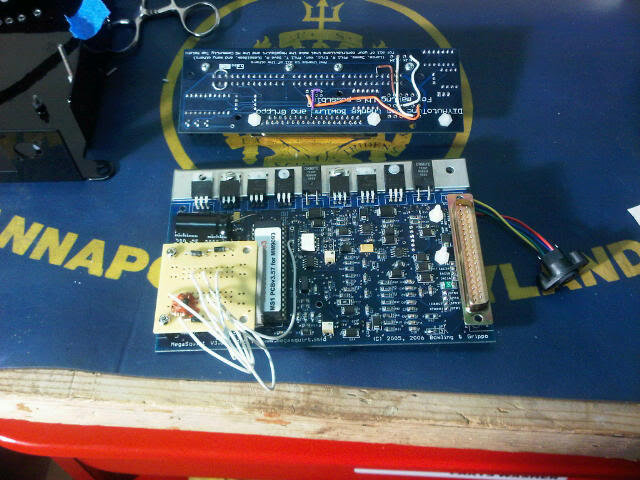
Worked on the squirt this evening. In addition to the standard MSPNP9093 stuff, the squirt has been modified for the following:
1. Variable TPS (Ref: MSPNP Manual � 5).
2. Water Injection Control Relay on JS0 (Ref: MS1 Extra Hardware Manual).
3. Spark Map Table Switching on JS9 (Ref: MS1 Extra Hardware Manual). I'm switching this with the AC relay control signal on pin 1J of the squirt. It will automatically switch to a spark table with ~5-10� more ignition advance in the idle region to offset the AC compressor load.
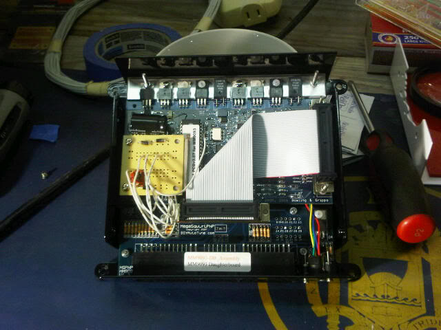
This picture shows the MS 3.57 board modified with my cobbled-up "grand-daughter" board along with the modified MSPNP daughter board:
It all fit back in the case nicely. All circuits checked at the external pins.
1. Variable TPS (Ref: MSPNP Manual � 5).
2. Water Injection Control Relay on JS0 (Ref: MS1 Extra Hardware Manual).
3. Spark Map Table Switching on JS9 (Ref: MS1 Extra Hardware Manual). I'm switching this with the AC relay control signal on pin 1J of the squirt. It will automatically switch to a spark table with ~5-10� more ignition advance in the idle region to offset the AC compressor load.
This picture shows the MS 3.57 board modified with my cobbled-up "grand-daughter" board along with the modified MSPNP daughter board:
It all fit back in the case nicely. All circuits checked at the external pins.
Reply
0
0


