Hybrid B6/ZM-DE engine build
 01-10-2012, 03:43 AM
#1
Junior Member
Thread Starter
iTrader: (1)

Join Date: Dec 2010
Location: California
Posts: 53
Total Cats: 21
My 1.6 turbo build.
The parts list as follows:
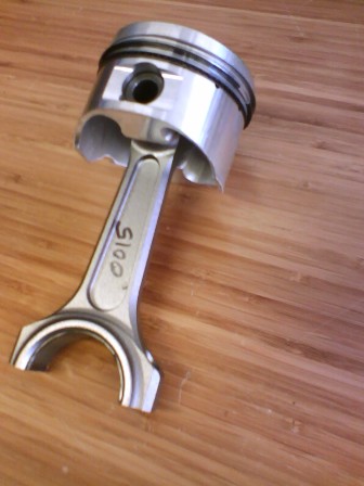
• Wiseco +1mm pistons and custom rings
• Carrillo A-beam rods
• ACL race bearings
• Supertech +1mm intake/exhaust valves
• Factory AT cams
• Ported head
• Polished and balanced crank
• Cometic head gasket
• ARP studs top and bottom
• Corksport Cam Gears
• Bountry Oil Pump Gears
• Custom sc40 tubular exhaust manifold
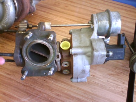
• Mini Cooper JCW turbo (KO3)
This build is intended to have a very modest output of 200-225hp. My parts selection is based on my day-to-day driving habits and commute, as well long-term durability and fuel consumption.
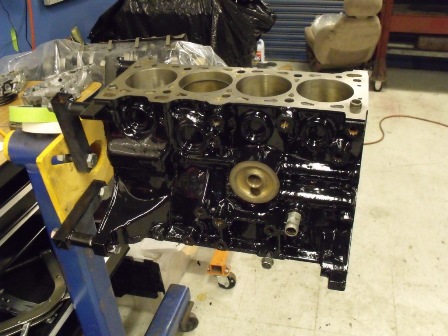
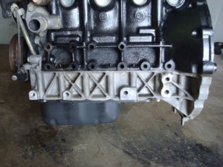
I started by polishing the inside of the engine block to remove any leftover casting debris and to aid in oil drain back to the oil pan. After I polished the inside of the block I decided to smooth the outside of the block as well in order to give the paint a smooth appearance. (Yes this was a lot of work)
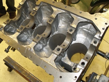
The oil passages from the oil pump to the oil filter mounting boss were ported and all the turns were radiused and enlarged.
I did various modifications to the oiling system based on my experience and research I have done over the last few years.
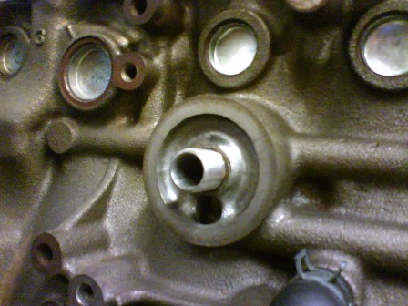
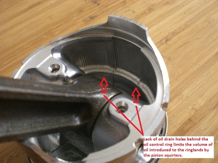
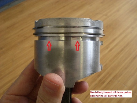
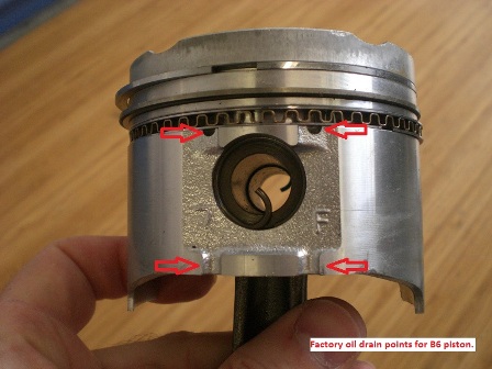
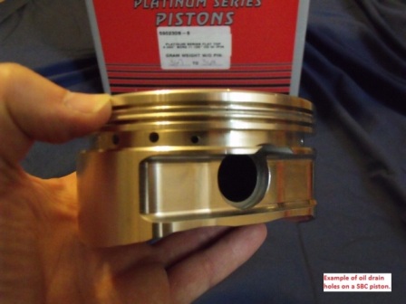
First I removed the oil squirters and plugged them with some bolts I modified. I did this to limit the amount of oil that must be controlled by the oil control ring. The stock Mazda pistons do not have oil drain holes drilled behind the oil control ring. Mazda used channels alongside piston skirt to channel excess oil from the oil control ring.
With the Wiseco pistons there are oil drain holes drilled in the ring lands behind the oil control ring, this is for oil drain purposes. However with the oil squirter in place the oil sprayed on the underside of the piston now has a path to the backside of the oil control ring and the ring must work harder to control the volume passing by. The oil squirters also increase the amount of windage within the crankcase, thus lowering engine efficiency.
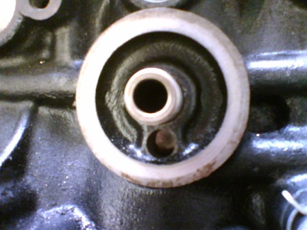
Removing the oil squirters should offset my other experiment. That is increasing the size of the oil restrictor to the cylinder head. I suspect a lack of oil flow/pressure is responsible for the infamous HLA tick. I drilled the restrictor from .089 to .095”.

The oil pump housing was also ported to improve flow and reduce cavitation.
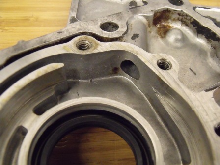
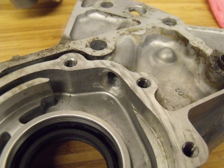
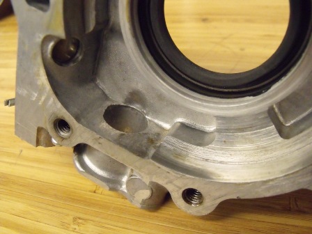
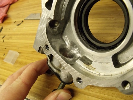
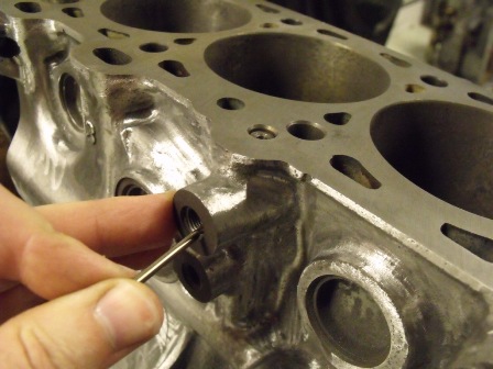
Rather than using the oil port on the exhaust side of the block as an oil feed to the turbo (which would lower the oil volume to the rear main bearing). I decided to drill the threaded boss under the intake manifold just above the stock oil pressure sending unit.
A small drill bit was use to intersect the oil passage leading to the cylinder head restrictor.
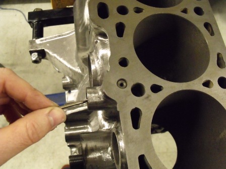
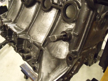
The exhaust side coolant supply port for the turbo was also drilled and taped for a Ľ NPT which is easier to find in a steel -6AN fitting.
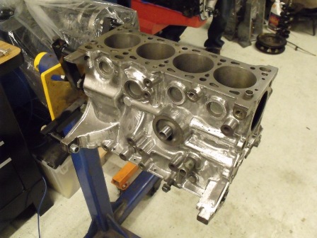
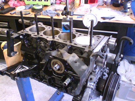
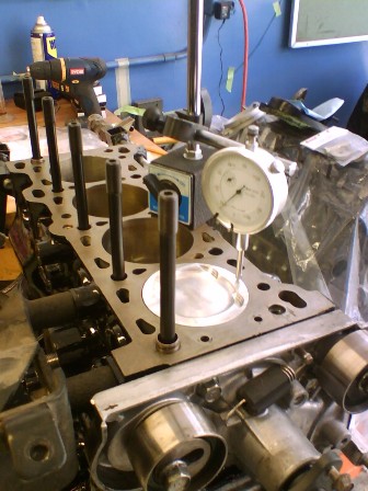
Once the block was prepped I had the cylinders bore and honed. I found during initial assembly that the Wiseco pistons sat -.020 in the cylinder. So I had the block decked to achieve a zero deck.
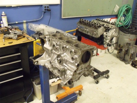
After the block came back from machining it was thoroughly cleaned and painted.
The bore clearance was set at .003, the mains at .0018 and rods at .0020
The pistons were installed and the piston to head clearance was checked, the clearance variation due to piston rock while cold was also factored into the clearance.
Originally I had planned to use the B6 cylinder head. I ported a spare head and did some flow comparisons on my flowbench to test various port shapes (The B6 head has a lot of material in the head and can accept a substantially larger port).
I decided to unshroud the valves and polish the combustion chambers as well as do a mild bowl blend around the valve seats but leave the ports stock in order to maximize port velocity. I did do substantial amount of work cleaning the upper portion of the cylinder head casting in order to remove casting debris and improve oil drain back to the pan, as well as drilling and tapping a fitting for the heater core on the back of the head just before the thermostat. The cams I choose are from an automatic B6, these cams have shorter duration and lift which I felt is well suited for my application.
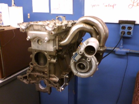
The exhaust manifold is a custom piece made from sc40 mild steel pipe. It was originally designed with a KKK k26 flange. I have since decided to use a k03 from a Mini Cooper S which provides a significant amount of boost by 1800rpm. This turbo is a twin scroll design which is easily adapted to the existing collector by welding a divider between the inner and outer cylinder pairs then twisting the divider in order to line up with the divider on the turbo.
The parts list as follows:
• Wiseco +1mm pistons and custom rings
• Carrillo A-beam rods
• ACL race bearings
• Supertech +1mm intake/exhaust valves
• Factory AT cams
• Ported head
• Polished and balanced crank
• Cometic head gasket
• ARP studs top and bottom
• Corksport Cam Gears
• Bountry Oil Pump Gears
• Custom sc40 tubular exhaust manifold
• Mini Cooper JCW turbo (KO3)
This build is intended to have a very modest output of 200-225hp. My parts selection is based on my day-to-day driving habits and commute, as well long-term durability and fuel consumption.
I started by polishing the inside of the engine block to remove any leftover casting debris and to aid in oil drain back to the oil pan. After I polished the inside of the block I decided to smooth the outside of the block as well in order to give the paint a smooth appearance. (Yes this was a lot of work)
The oil passages from the oil pump to the oil filter mounting boss were ported and all the turns were radiused and enlarged.
I did various modifications to the oiling system based on my experience and research I have done over the last few years.
First I removed the oil squirters and plugged them with some bolts I modified. I did this to limit the amount of oil that must be controlled by the oil control ring. The stock Mazda pistons do not have oil drain holes drilled behind the oil control ring. Mazda used channels alongside piston skirt to channel excess oil from the oil control ring.
With the Wiseco pistons there are oil drain holes drilled in the ring lands behind the oil control ring, this is for oil drain purposes. However with the oil squirter in place the oil sprayed on the underside of the piston now has a path to the backside of the oil control ring and the ring must work harder to control the volume passing by. The oil squirters also increase the amount of windage within the crankcase, thus lowering engine efficiency.
Removing the oil squirters should offset my other experiment. That is increasing the size of the oil restrictor to the cylinder head. I suspect a lack of oil flow/pressure is responsible for the infamous HLA tick. I drilled the restrictor from .089 to .095”.
The oil pump housing was also ported to improve flow and reduce cavitation.
Rather than using the oil port on the exhaust side of the block as an oil feed to the turbo (which would lower the oil volume to the rear main bearing). I decided to drill the threaded boss under the intake manifold just above the stock oil pressure sending unit.
A small drill bit was use to intersect the oil passage leading to the cylinder head restrictor.
The exhaust side coolant supply port for the turbo was also drilled and taped for a Ľ NPT which is easier to find in a steel -6AN fitting.
Once the block was prepped I had the cylinders bore and honed. I found during initial assembly that the Wiseco pistons sat -.020 in the cylinder. So I had the block decked to achieve a zero deck.
After the block came back from machining it was thoroughly cleaned and painted.
The bore clearance was set at .003, the mains at .0018 and rods at .0020
The pistons were installed and the piston to head clearance was checked, the clearance variation due to piston rock while cold was also factored into the clearance.
Originally I had planned to use the B6 cylinder head. I ported a spare head and did some flow comparisons on my flowbench to test various port shapes (The B6 head has a lot of material in the head and can accept a substantially larger port).
I decided to unshroud the valves and polish the combustion chambers as well as do a mild bowl blend around the valve seats but leave the ports stock in order to maximize port velocity. I did do substantial amount of work cleaning the upper portion of the cylinder head casting in order to remove casting debris and improve oil drain back to the pan, as well as drilling and tapping a fitting for the heater core on the back of the head just before the thermostat. The cams I choose are from an automatic B6, these cams have shorter duration and lift which I felt is well suited for my application.
The exhaust manifold is a custom piece made from sc40 mild steel pipe. It was originally designed with a KKK k26 flange. I have since decided to use a k03 from a Mini Cooper S which provides a significant amount of boost by 1800rpm. This turbo is a twin scroll design which is easily adapted to the existing collector by welding a divider between the inner and outer cylinder pairs then twisting the divider in order to line up with the divider on the turbo.

Reply
 5
5

5
 01-10-2012, 05:00 AM
#3
Junior Member
Thread Starter
iTrader: (1)
Join Date: Dec 2010
Location: California
Posts: 53
Total Cats: 21
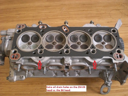
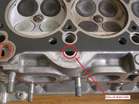
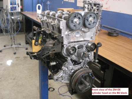
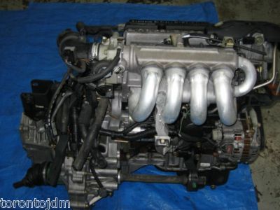
While doing some research on various Mazda engines I came across a 1.6L ZM-DE engine in a 2000 Protégé. The engine block looked remarkably close to a B6/BP so I did some disassembly to inspect. What I found is that the ZM-DE shares all the same dimensions with the B6 engine except it has an aluminum lower split-block design, and two extra oil drains on the exhaust side of the block/head assembly. Other than that the block, rotating assembly and accessories are identical.
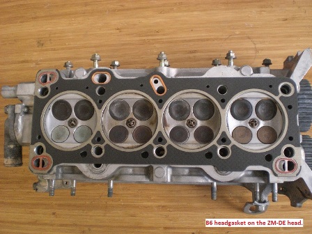
Here are a couple photos of a B6 head gasket on a ZM-DE head.
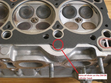
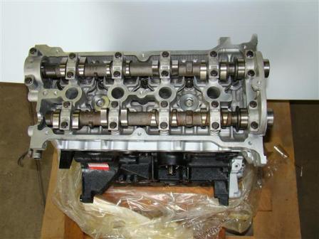
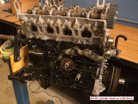
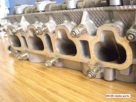
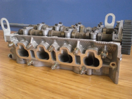
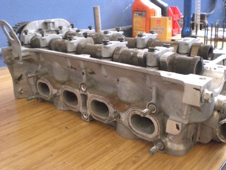
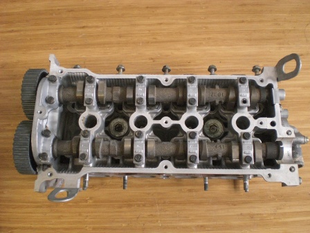
Here are some photos of the ZM-DE cylinder head on a B6 block.
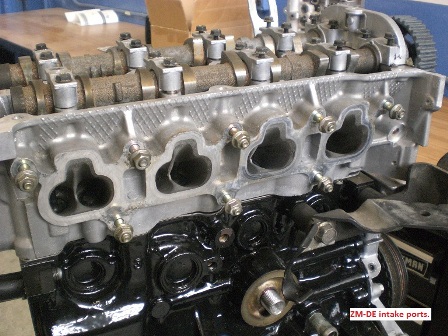
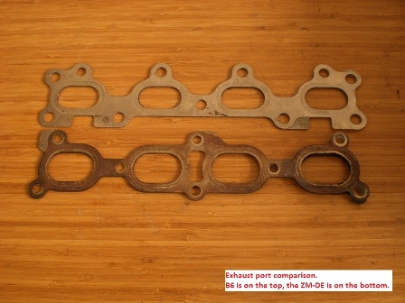
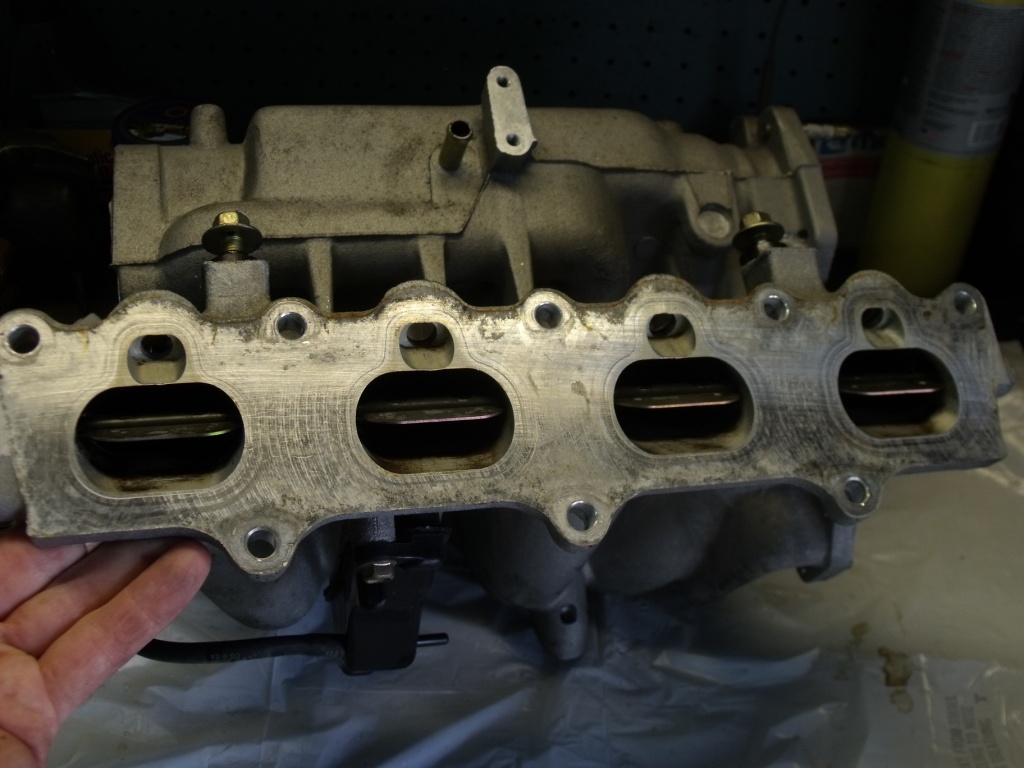
I took various measurements of the head to compare to the stock B6 head. The intake ports on the ZM-DE head measure 2.10 X 1.115 and are significantly higher from the deck surface and have a straighter shot to the valve than the B6 head. A visual comparison between the ZM-DE intake ports and the BP-4W intake ports indicates that they are almost identical (the ZM-DE is perhaps a little better due to the valve angles). The exhaust ports measure 1.7 X 1.065 and are visibly larger than the B6 ports and have a better transition at the port divider.
Here is a photo of the B6 and ZM-DE exhaust manifold gaskets (the ZM-DE is on the bottom).
The cam duration I found on the Protégé forums indicate the ZM-DE has and intake duration of 226*@.003, and I measured the lobe lift at .325” using micrometers. The exhaust duration is 233* @.003 and lobe lift is .310
• IVO = 1* BTDC
• IVC = 45* ABDC
• EVO = 52* BBDC
• EVC = 1* ATDC
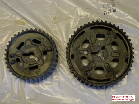
The lifters are also solid not hydraulic like the B6. The lobes are also much narrower than those found on the B6/BP engines. The lobes measure .400 wide at the nose of the cam lobe and tapers to .220 at the heel of the lobe. The cam spacing is 3.75 inches, which is much narrower than the “B” series engines. In order the get the valve angles tighter and the cams closer together the cam gears are smaller.
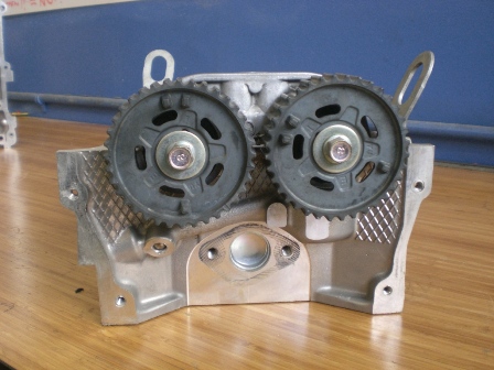
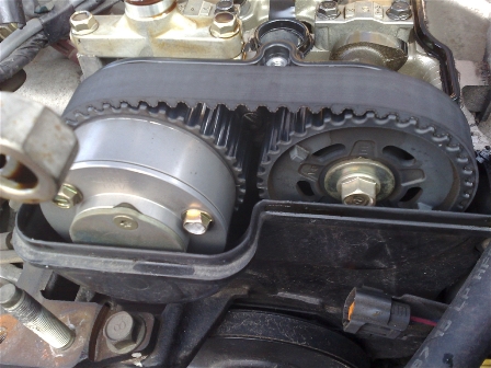
Here is a comparison between the ZM-DE cam gear and the BP-4W.
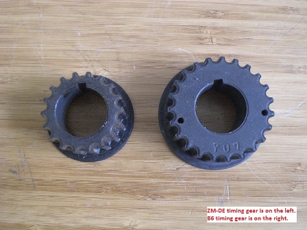
The lower drive gear on the crank must be paired with the upper.
Here are some photos of the upper portion of the cylinder head. Here you can see how much tighter the valve angles are. Tighter valve angles result in shallower combustion chambers which are generally more knock resistant.
I have yet to cc the combustion chambers. I will post the numbers when they become available. Here are the combustion chambers.
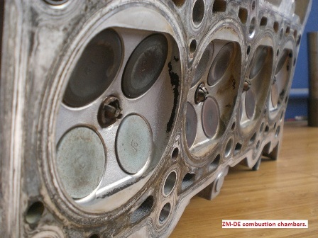
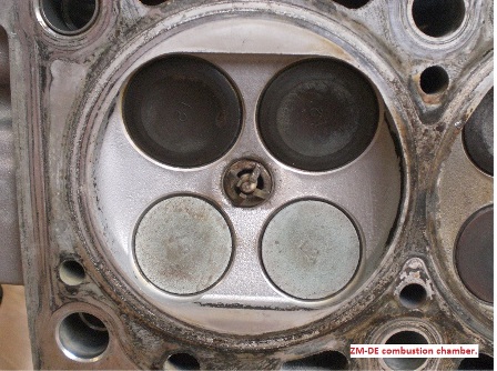
Because the combustion chambers are shallow the pistons have a significant dish to achieve the required compression ratio.
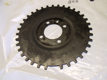
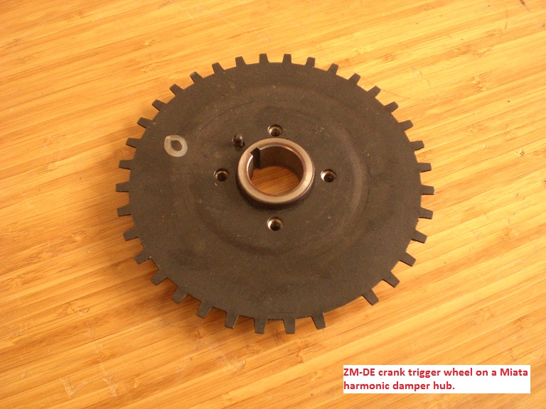
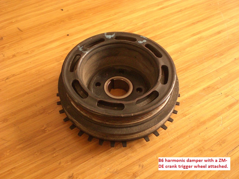
I was originally fabricating my own 36-1 ignition trigger. This design used a wheel that brazes to the damper hub.
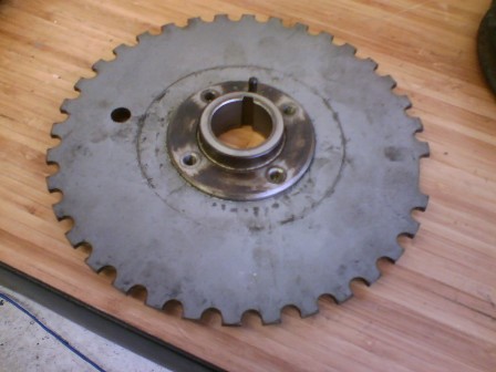
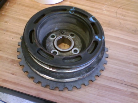
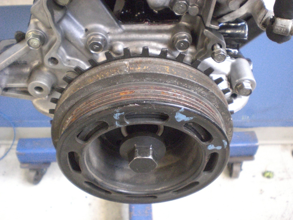
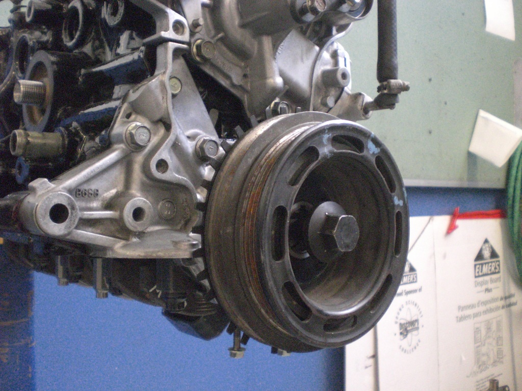
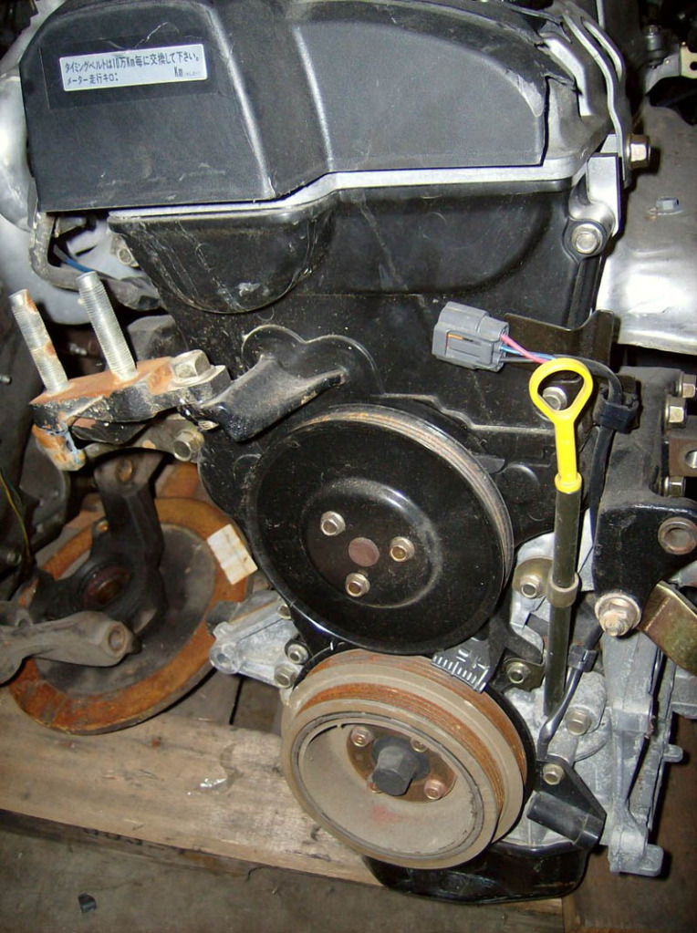
I then came across this while removing the lower timing belt drive gear from the ZM-DE engine.
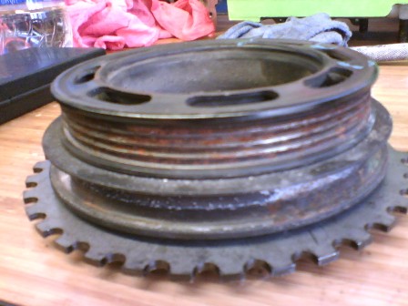
I took and laid a 99’ crank trigger wheel I had over the top of the ZM-DE trigger wheel.
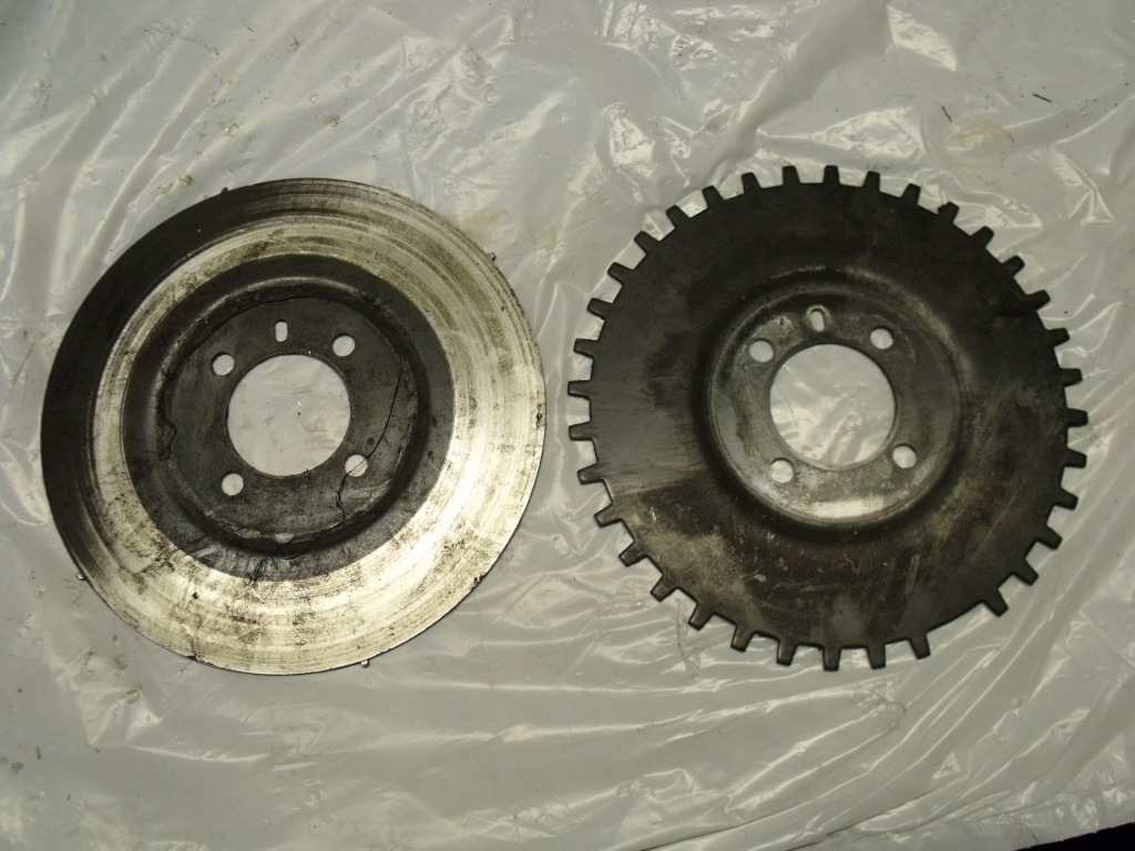
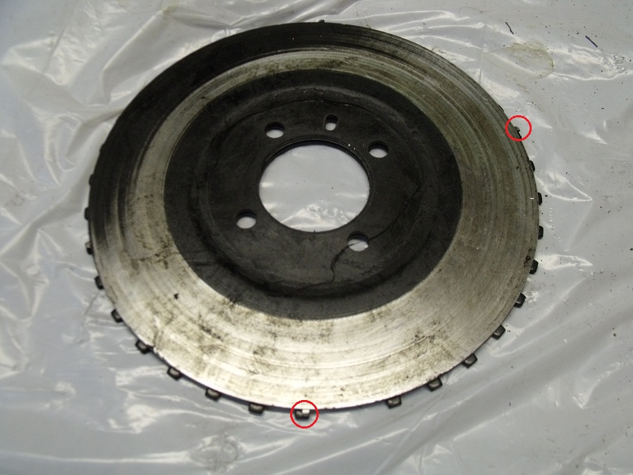
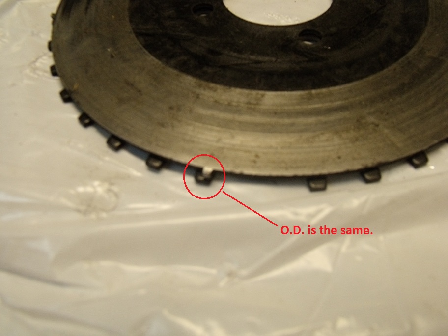
O.D. and the center bolt pattern are identical!
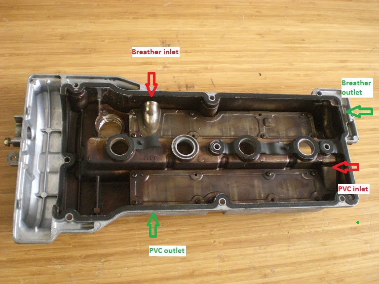
I had also purchased a 99’ BP-4W valve cover with the intention to cut and weld the front portion of the cover with the cam angle sensor to my original B6 valve cover. However the ZM-DE valve cover comes with a cam angle sensor built in. So that solves problem of generating a cam sync pulse for the Megasquirt.
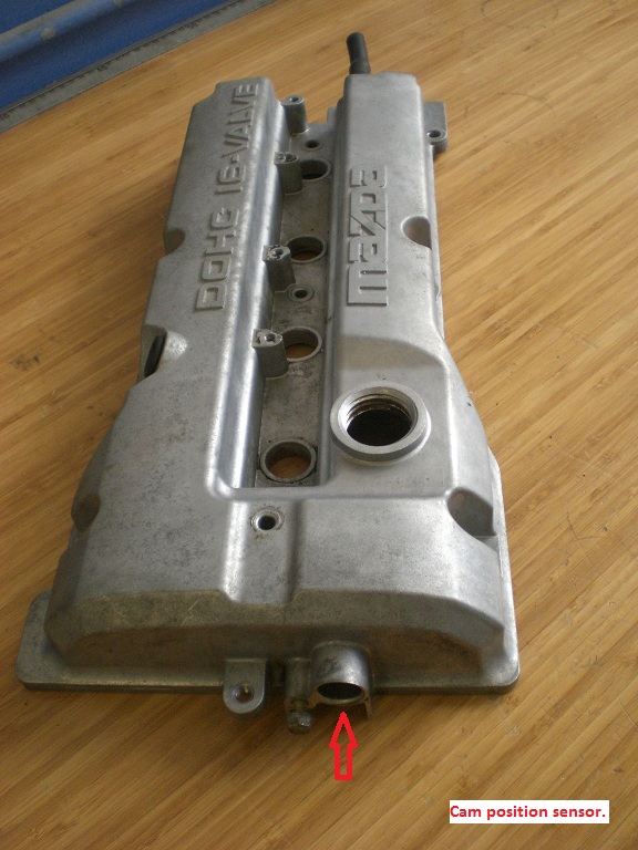
The valve cover breathers also look to be an improvement over the B6. The baffles at first glance appear to be higher flowing and have longer passages to help separate the oil from the blowby gases.
Out of curiosity I checked to see if the original CAS would fit.
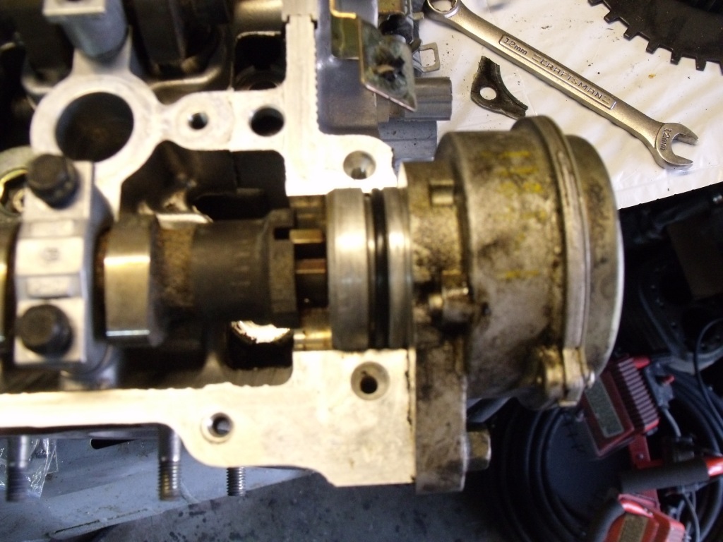
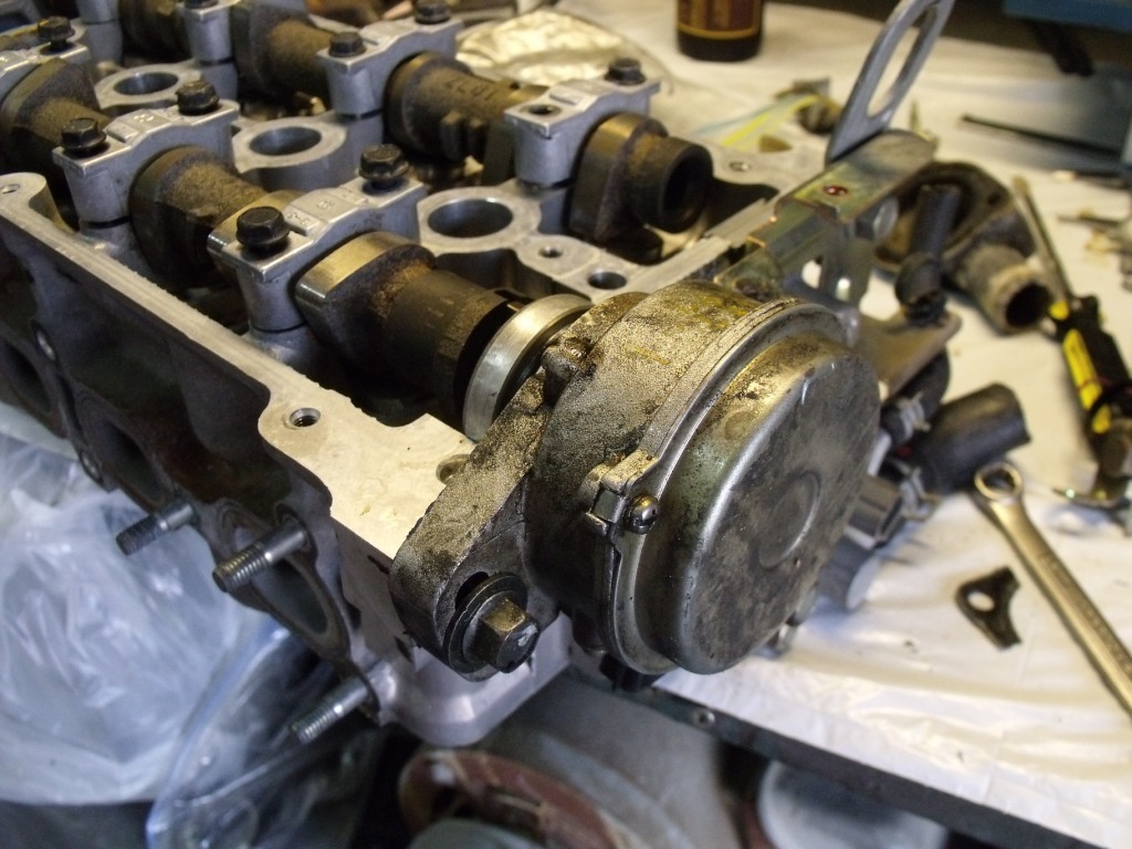
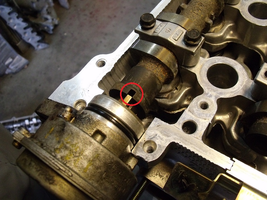
Everything bolts up and seals properly, however the one problem I found with running the stock CAS is the drive lug does not fully engage with the back of the exhaust cam. There are a couple ways to solve this problem.
1) Lathe the backside of the CAS so it sits further in the head
2) Remove the drive lug from the CAS and weld/extend the ears
3) Mill the backside of the head so the CAS sits closer to the cam
The first solution would be very simple, except if the CAS fails you would need to repair the original, or lathe the new one (kind of a pain). The second is a simple solution, however that “T” shaped drive lug is harder to get off than expected and damage could occur to the CAS. The third option is a good one, except mounting the head in mill could take some time.
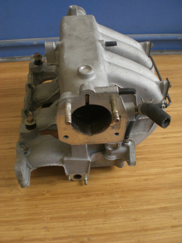
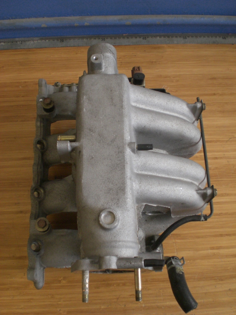
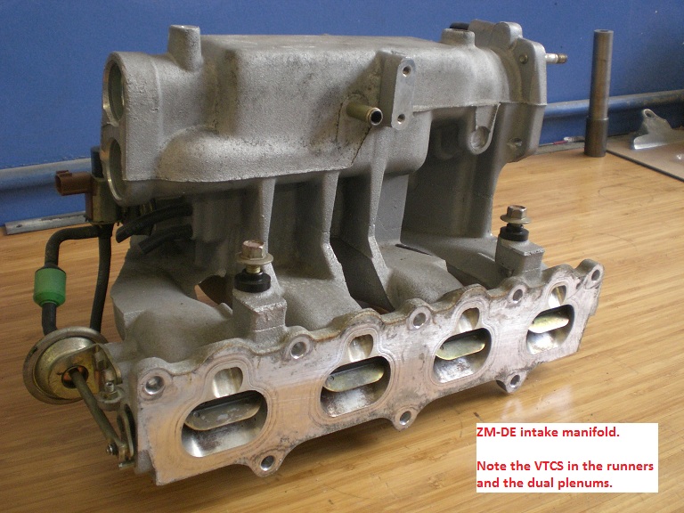
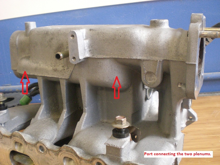
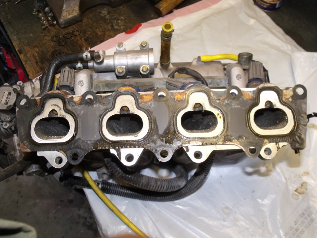
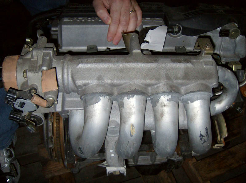
The intake manifold has some nice features.
• No water circulation passages
• Long tapered ports
• VTCS (most people remove)
• Equal length runners
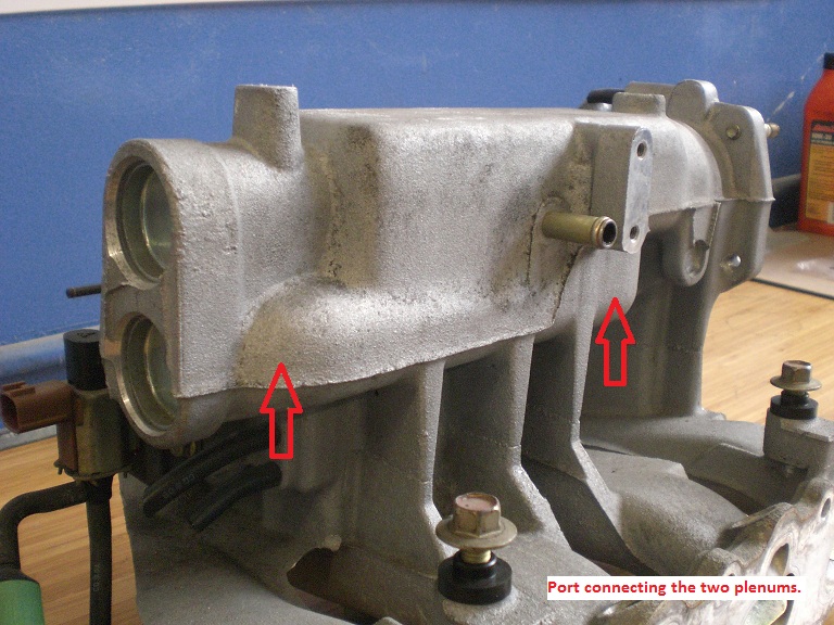
• Dual plenums
The most interesting feature is the dual plenums. The primary plenum is very small for throttle response. At the back of the primary plenum is a port that connects to a secondary plenum under the primary which I assume is being used as a Helmholtz resonation chamber.
My plans are to remove the primary and secondary plenums and weld a stock B6 plenum to the ZM-DE runners. This may not be the best flowing system by it would be a simple way of getting all the vacuum ports and various idle components functioning. I also live in California and would like to keep the engine modifications as discrete as possible.
The VTCS many people have stated only operates during warmup. The research I have done show that “tumble valves” increase the combustion rate and reduce the chances of detonation. Obviously these valves do not present a restriction for my power levels. If I was racing the engine I may remove them.
I am contemplating a way of using them as an IRTB system, which would provide better throttle response, and would limit the amount of exhaust gas reversion into the intake ports at lower throttle inputs (if I ever run cams with a higher valve overlap).
Here is a photo of the stock B6 intake manifold with the ZM-DE intake gasket laid over the top. The port height indicated by the gasket is misleading because the intake mounting surface of the ZM-DE is machined at an angle. However the width of the ports are a correct representation of the differences in port size.
The head bolts used by the ZM-DE are a little shorter than those found in the B6/BP engines. They also use a hex head socket. McMaster-Carr sells this same bolt (M10X1.50 X 100mm) in a 12.9 grade rated at 174,000psi, which is more than adequate.
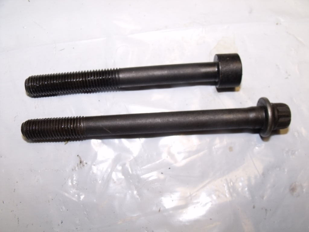
(Do not be misled by the thread length. The threads in the ZM-DE block are the same depth.)
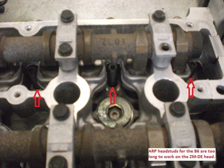
Because the ZM-DE shares all the same dimensions as the B6 (except the extra oil drains) the head gasket is backward compatible. The head gasket is a MLS style gasket with two layers. It is significantly thinner than the stock B6 composite gasket and I would not recommend its use on stock pistons due to the fact that they protrude .010 from the deck of the block and may contact the cylinder head if the ZM-DE head gasket is used.
If aftermarket pistons are used this headgasket should work fine and I assume would be a cost effective alternative to the Cometic head gaskets.
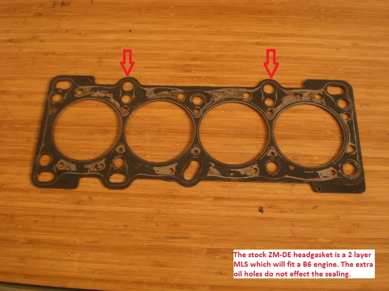
Here are a couple photos of a B6 head gasket on a ZM-DE head.
Here are some photos of the ZM-DE cylinder head on a B6 block.
I took various measurements of the head to compare to the stock B6 head. The intake ports on the ZM-DE head measure 2.10 X 1.115 and are significantly higher from the deck surface and have a straighter shot to the valve than the B6 head. A visual comparison between the ZM-DE intake ports and the BP-4W intake ports indicates that they are almost identical (the ZM-DE is perhaps a little better due to the valve angles). The exhaust ports measure 1.7 X 1.065 and are visibly larger than the B6 ports and have a better transition at the port divider.
Here is a photo of the B6 and ZM-DE exhaust manifold gaskets (the ZM-DE is on the bottom).
The cam duration I found on the Protégé forums indicate the ZM-DE has and intake duration of 226*@.003, and I measured the lobe lift at .325” using micrometers. The exhaust duration is 233* @.003 and lobe lift is .310
• IVO = 1* BTDC
• IVC = 45* ABDC
• EVO = 52* BBDC
• EVC = 1* ATDC
The lifters are also solid not hydraulic like the B6. The lobes are also much narrower than those found on the B6/BP engines. The lobes measure .400 wide at the nose of the cam lobe and tapers to .220 at the heel of the lobe. The cam spacing is 3.75 inches, which is much narrower than the “B” series engines. In order the get the valve angles tighter and the cams closer together the cam gears are smaller.
Here is a comparison between the ZM-DE cam gear and the BP-4W.
The lower drive gear on the crank must be paired with the upper.
Here are some photos of the upper portion of the cylinder head. Here you can see how much tighter the valve angles are. Tighter valve angles result in shallower combustion chambers which are generally more knock resistant.
I have yet to cc the combustion chambers. I will post the numbers when they become available. Here are the combustion chambers.
Because the combustion chambers are shallow the pistons have a significant dish to achieve the required compression ratio.
I was originally fabricating my own 36-1 ignition trigger. This design used a wheel that brazes to the damper hub.
I then came across this while removing the lower timing belt drive gear from the ZM-DE engine.
I took and laid a 99’ crank trigger wheel I had over the top of the ZM-DE trigger wheel.
O.D. and the center bolt pattern are identical!
I had also purchased a 99’ BP-4W valve cover with the intention to cut and weld the front portion of the cover with the cam angle sensor to my original B6 valve cover. However the ZM-DE valve cover comes with a cam angle sensor built in. So that solves problem of generating a cam sync pulse for the Megasquirt.
The valve cover breathers also look to be an improvement over the B6. The baffles at first glance appear to be higher flowing and have longer passages to help separate the oil from the blowby gases.
Out of curiosity I checked to see if the original CAS would fit.
Everything bolts up and seals properly, however the one problem I found with running the stock CAS is the drive lug does not fully engage with the back of the exhaust cam. There are a couple ways to solve this problem.
1) Lathe the backside of the CAS so it sits further in the head
2) Remove the drive lug from the CAS and weld/extend the ears
3) Mill the backside of the head so the CAS sits closer to the cam
The first solution would be very simple, except if the CAS fails you would need to repair the original, or lathe the new one (kind of a pain). The second is a simple solution, however that “T” shaped drive lug is harder to get off than expected and damage could occur to the CAS. The third option is a good one, except mounting the head in mill could take some time.
The intake manifold has some nice features.
• No water circulation passages
• Long tapered ports
• VTCS (most people remove)
• Equal length runners
• Dual plenums
The most interesting feature is the dual plenums. The primary plenum is very small for throttle response. At the back of the primary plenum is a port that connects to a secondary plenum under the primary which I assume is being used as a Helmholtz resonation chamber.
My plans are to remove the primary and secondary plenums and weld a stock B6 plenum to the ZM-DE runners. This may not be the best flowing system by it would be a simple way of getting all the vacuum ports and various idle components functioning. I also live in California and would like to keep the engine modifications as discrete as possible.
The VTCS many people have stated only operates during warmup. The research I have done show that “tumble valves” increase the combustion rate and reduce the chances of detonation. Obviously these valves do not present a restriction for my power levels. If I was racing the engine I may remove them.
I am contemplating a way of using them as an IRTB system, which would provide better throttle response, and would limit the amount of exhaust gas reversion into the intake ports at lower throttle inputs (if I ever run cams with a higher valve overlap).
Here is a photo of the stock B6 intake manifold with the ZM-DE intake gasket laid over the top. The port height indicated by the gasket is misleading because the intake mounting surface of the ZM-DE is machined at an angle. However the width of the ports are a correct representation of the differences in port size.
The head bolts used by the ZM-DE are a little shorter than those found in the B6/BP engines. They also use a hex head socket. McMaster-Carr sells this same bolt (M10X1.50 X 100mm) in a 12.9 grade rated at 174,000psi, which is more than adequate.
(Do not be misled by the thread length. The threads in the ZM-DE block are the same depth.)
Because the ZM-DE shares all the same dimensions as the B6 (except the extra oil drains) the head gasket is backward compatible. The head gasket is a MLS style gasket with two layers. It is significantly thinner than the stock B6 composite gasket and I would not recommend its use on stock pistons due to the fact that they protrude .010 from the deck of the block and may contact the cylinder head if the ZM-DE head gasket is used.
If aftermarket pistons are used this headgasket should work fine and I assume would be a cost effective alternative to the Cometic head gaskets.
Reply
1
1
01-10-2012, 05:12 AM
#4
Junior Member
Thread Starter
iTrader: (1)
Join Date: Dec 2010
Location: California
Posts: 53
Total Cats: 21
There is a Japanese spec engine referred to as the ZL-VE which is 1.5L with a bore of 78mm and stroke of 83.6mm. This engine is equipped with a cam phaser on the intake cam similar to the 01+ BP engines. This cylinder head would also be a bolt-on for the B6 Miata block.
My future plans may include using the ZL-VE head with a larger turbo such as the k04 found on the Pontiac Solstice GXP. The VVT head would retain the spool characteristics of the k03 but with less exhaust backpressure and more topend.
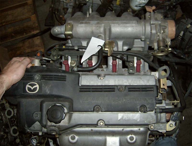
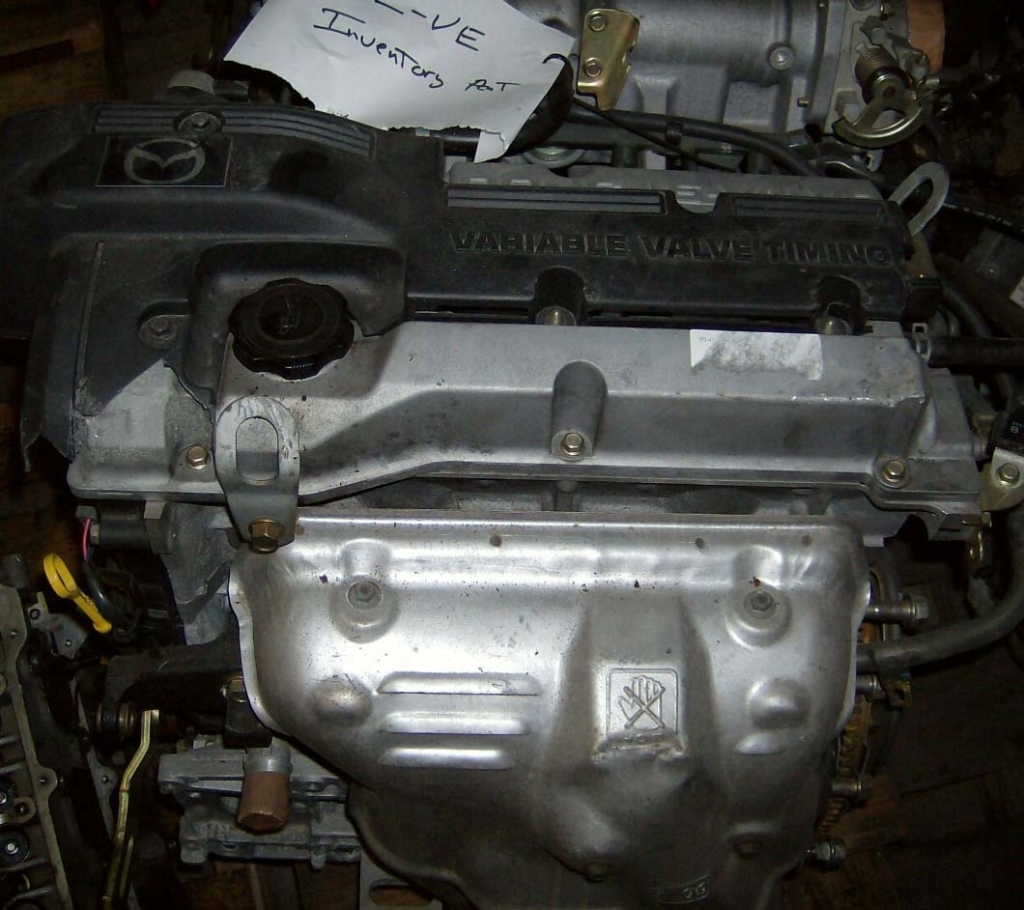
Note the ZL-VE intake manifold also uses the same dual plenum intake manifold. From what I have found online the ZM-DE intake manifold is an upgrade for the ZL-VE.
My future plans may include using the ZL-VE head with a larger turbo such as the k04 found on the Pontiac Solstice GXP. The VVT head would retain the spool characteristics of the k03 but with less exhaust backpressure and more topend.
Note the ZL-VE intake manifold also uses the same dual plenum intake manifold. From what I have found online the ZM-DE intake manifold is an upgrade for the ZL-VE.
Reply
2
2


 01-11-2012, 02:13 AM
#15

Fantastic thread to say the least. Have you flow tested the ZM head (since you mention having the equipment) vs the stock B6 head? I didn't see that mentioned anywhere if you have. And definitely keep this updated as to the use of the ZL VVT head if you get it installed.
Reply
0
0
01-14-2012, 05:35 AM
#16
Junior Member
Thread Starter
iTrader: (1)
Join Date: Dec 2010
Location: California
Posts: 53
Total Cats: 21
Originally Posted by Faeflora
One question though. Why all this effort for 250hp?
One question though. Why all this effort for 250hp?
It’s best not to judge an engine based only on its peak power output. Area under the curve is a better representation of the engines true output (most people who talk only about big numbers know nothing about cars). For example, say we have an engine where the turbo is sized too big and the boost comes in at 5000rpm and then it pulls hard to 7000rpm where it makes 250hp and then dies because the cylinder heads don’t flow well (or not running enough boost). Thus producing a narrow useable powerband and a car that is hard to drive fast without a close ratio gearbox. Then consider an engine which is making good boost at 2000rpm and pulls hard to 7000rpm, this engine has lots of midrange torque and a wide useable powerband that pulls strong out of the turns and is more forgiving of driver error. That is what I am building. Ultimately I would like to get about 300hp out of the engine but my current turbo does not provide the CFM necessary
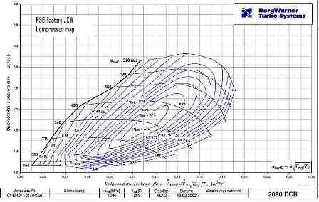
(The Mini Cooper turbo has a 36mm inducer and 49mm exducer. I need a turbo that flows at least 25 lbs/min which = .1889 kg/sec to make 250hp. At a 2.2 pressure ratio (18psi) and a .1889kg/sec flowrate this turbo is operating at 60% efficiency. So 250hp is actually optimistic for this turbo.
The K04 has a 42mm inducer and a 56mm exducer, with a flowrate of .19kg/sec @ 18psi which is right within the peak efficiency island.)
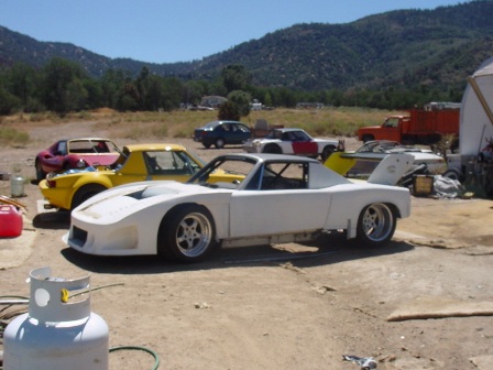
This is the car I am finishing which is my street/track terror, the miata is my daily driver.
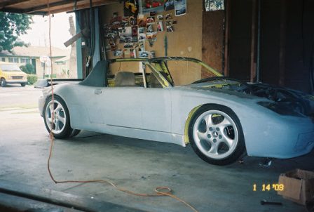
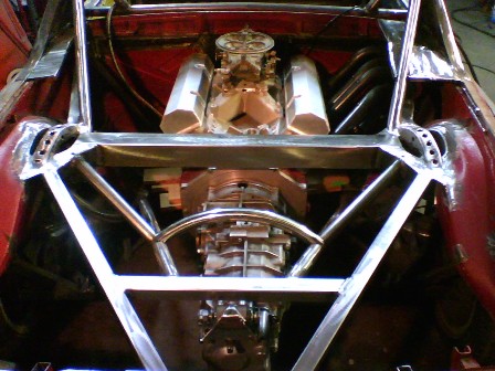
2400lbs with a 525hp small block chevy and a g50 transaxle.
Finished this a few years back for a customer.
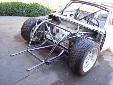
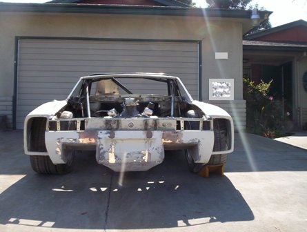
2200lbs with 700hp.
Originally Posted by Fireindc
Very informative. What kind of benefits are you expecting from this VVT head? Spool gains? Top end?
Very informative. What kind of benefits are you expecting from this VVT head? Spool gains? Top end?
• IVO = -3* to +32* BBDC
• IVC = 53* to +18* ABDC
Altering the IVC point changes where the engine makes torque. (a later point produces more topend, earlier produces more lowend).
Closing the intake valve sooner will generate more lowend torque which will help spool the turbo. Then by rotating the cam gear to retard the cam, you close the intake valve later creating more topend.
Originally Posted by bcrx7
Aluminum at 1000F expands about 0.012in and even more when forged. Does your head gasket allow enough expansion of the piston so it is not interfering with the head?
Aluminum at 1000F expands about 0.012in and even more when forged. Does your head gasket allow enough expansion of the piston so it is not interfering with the head?
The surface of a piston is protected by a thin boundary layer. When the shockwave produced by detonation occurs, the boundary layer is distorted/removed from the surface of the piston and the combustion gases are allowed to contact the surface of the piston, this is why you often see erosion around the ringlands of a piston that has be subjected to detonation.
To answer your other question. The stock B6 pistons actually sit .010 out the top of the block. If I recall correctly the stock headgasket is .056 compressed, that leaves .046 of clearance between the piston and head. Most engine builders do not recommend running less than .035 of clearance. (unless you have small bores, tight bore clearances, and strong rods with lightweight pistons to minimize rod stretch).
My engine has a zero deck meaning the piston is flush with the deck. My headgasket has a compressed thickness of .040, giving me a clearance of .040.
However the pistons rock in the bore which effects the clearance. I measured .005-.008 change in piston to deck clearance while cold. Of course once the engine is at operation temperature the pistons will no longer rock in the bore.
I think on my next build I will install Supertech pistons and run tighter clearances.
Originally Posted by matthewdesigns
Fantastic thread to say the least. Have you flow tested the ZM head (since you mention having the equipment) vs the stock B6 head? I didn't see that mentioned anywhere if you have. And definitely keep this updated as to the use of the ZL VVT head if you get it installed.
Fantastic thread to say the least. Have you flow tested the ZM head (since you mention having the equipment) vs the stock B6 head? I didn't see that mentioned anywhere if you have. And definitely keep this updated as to the use of the ZL VVT head if you get it installed.
Yes, I have a flowbench but it is a custom design, built for testing wet flow characteristics at very high vacuum levels around 136 inches of water (28 is what everyone else tests at). I can reconfigure my machine to test at lower pressures but there is no guarantee its numbers will be accurate with say a Superflow 600 due to calibration differences. What I can do are comparison tests to evaluate the flow differences between the B6, BP-4W and ZM-DE (all of which I have laying around).
I’m not sure when I will get around to doing the testing. I’ve got a lot of projects that need attention.
Reply
0
0

 01-18-2012, 04:15 PM
#20
Pistons don’t operate at 1000*F. They would fall apart!
The surface of a piston is protected by a thin boundary layer. When the shockwave produced by detonation occurs, the boundary layer is distorted/removed from the surface of the piston and the combustion gases are allowed to contact the surface of the piston, this is why you often see erosion around the ringlands of a piston that has be subjected to detonation.
To answer your other question. The stock B6 pistons actually sit .010 out the top of the block. If I recall correctly the stock headgasket is .056 compressed, that leaves .046 of clearance between the piston and head. Most engine builders do not recommend running less than .035 of clearance. (unless you have small bores, tight bore clearances, and strong rods with lightweight pistons to minimize rod stretch).
My engine has a zero deck meaning the piston is flush with the deck. My headgasket has a compressed thickness of .040, giving me a clearance of .040.
However the pistons rock in the bore which effects the clearance. I measured .005-.008 change in piston to deck clearance while cold. Of course once the engine is at operation temperature the pistons will no longer rock in the bore.
I think on my next build I will install Supertech pistons and run tighter clearances.
Looking good. Keep us posted!
Reply
0
0


