Nothing to see here, just project Sisyphus, move along
 08-30-2015, 12:27 AM
#1902
Elite Member
Thread Starter
iTrader: (37)

Join Date: Apr 2010
Location: Very NorCal
Posts: 10,441
Total Cats: 1,899
Ungh! Stupid ginormous Treadstone intercooler is being a bastard. Sunburned, dehydrated and frustrated I eventually gave up when it got to dark to work. I knew this was going to suck but I guess I was in denial as to how much of a PITA it was going to be. I'll hit it again tomorrow.
I need to cut some steel out of the passenger side radiator mount to get the intercooler where I want it. Hornets cardboard templates are super helpful, though I'm going to have to do some work on the "bottom" section as it does not quite line up with the NB nose, and there are some additional screw holes I can use for duct mounting.
Almost there, tomorrow should see plenty of progress now that I've spent most of today figuring out how not to do this.

Reply
 0
0

0
08-30-2015, 11:05 PM
#1903
Elite Member
Thread Starter
iTrader: (37)
Join Date: Apr 2010
Location: Very NorCal
Posts: 10,441
Total Cats: 1,899
Progress was made.
Step 1 was to do some cutting.
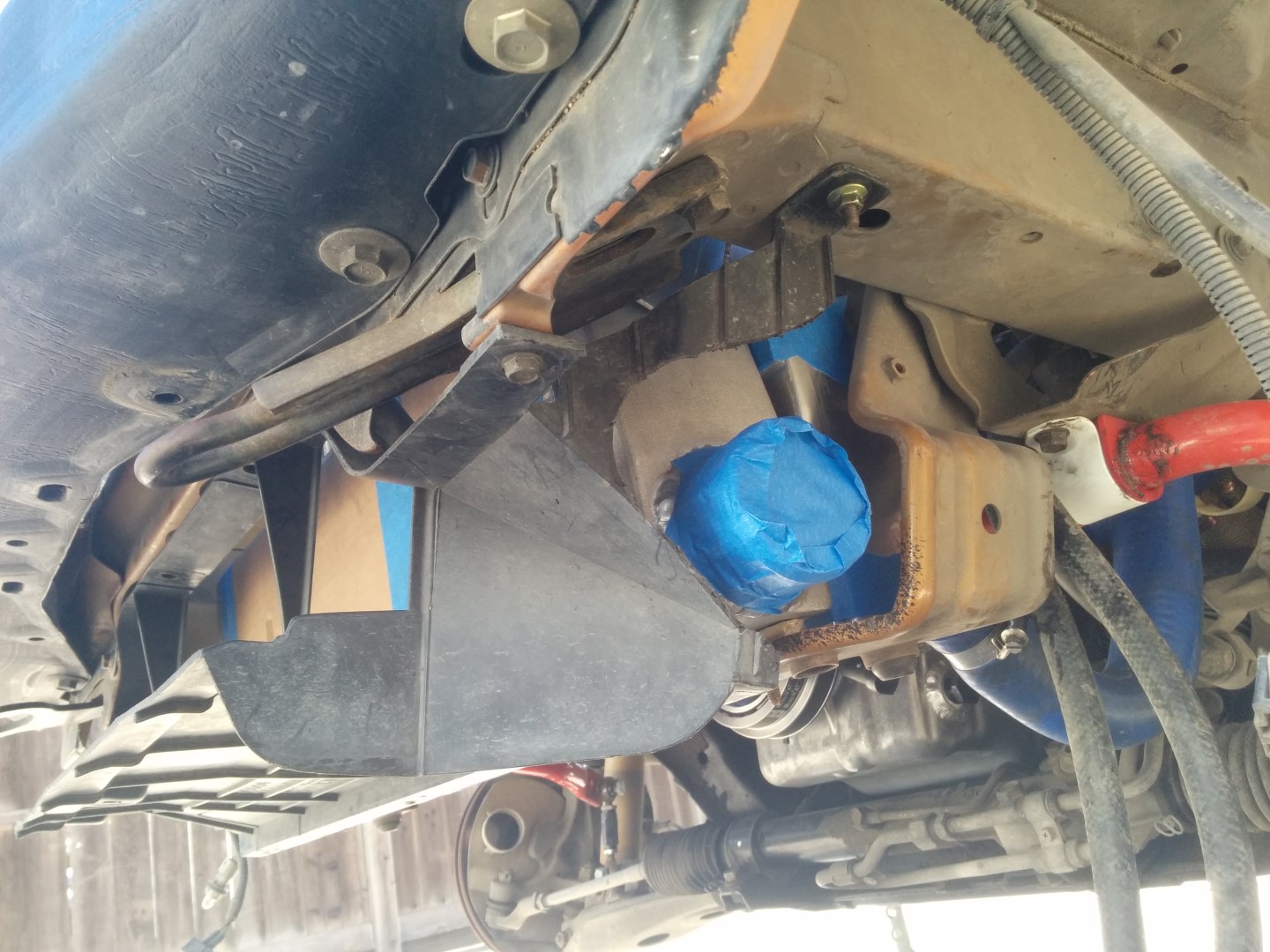
Chuck the intercooler up there and now there is clearance.
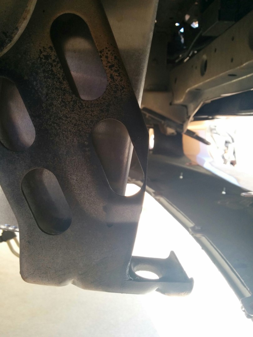
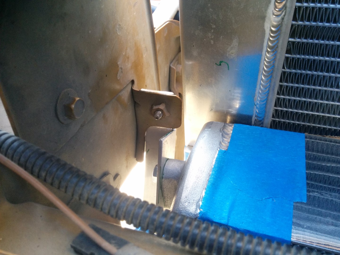
Looking up from the bottom you can just barely see the tab for the AC condenser mount. I plan on using this for the upper intercooler mount.
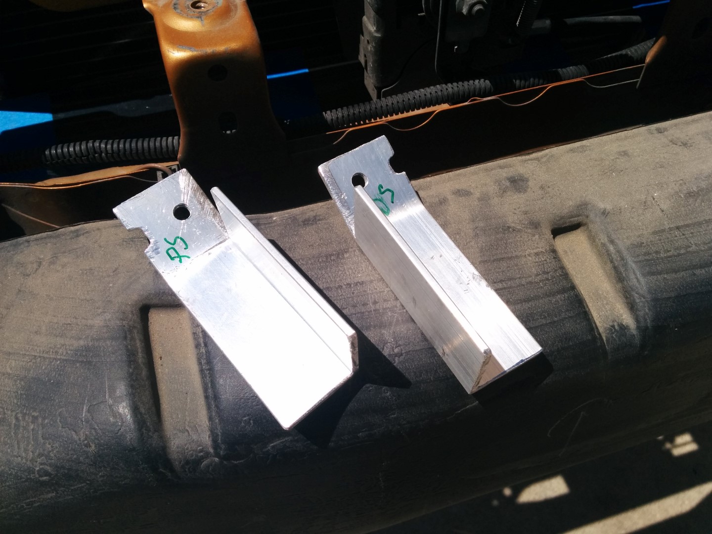
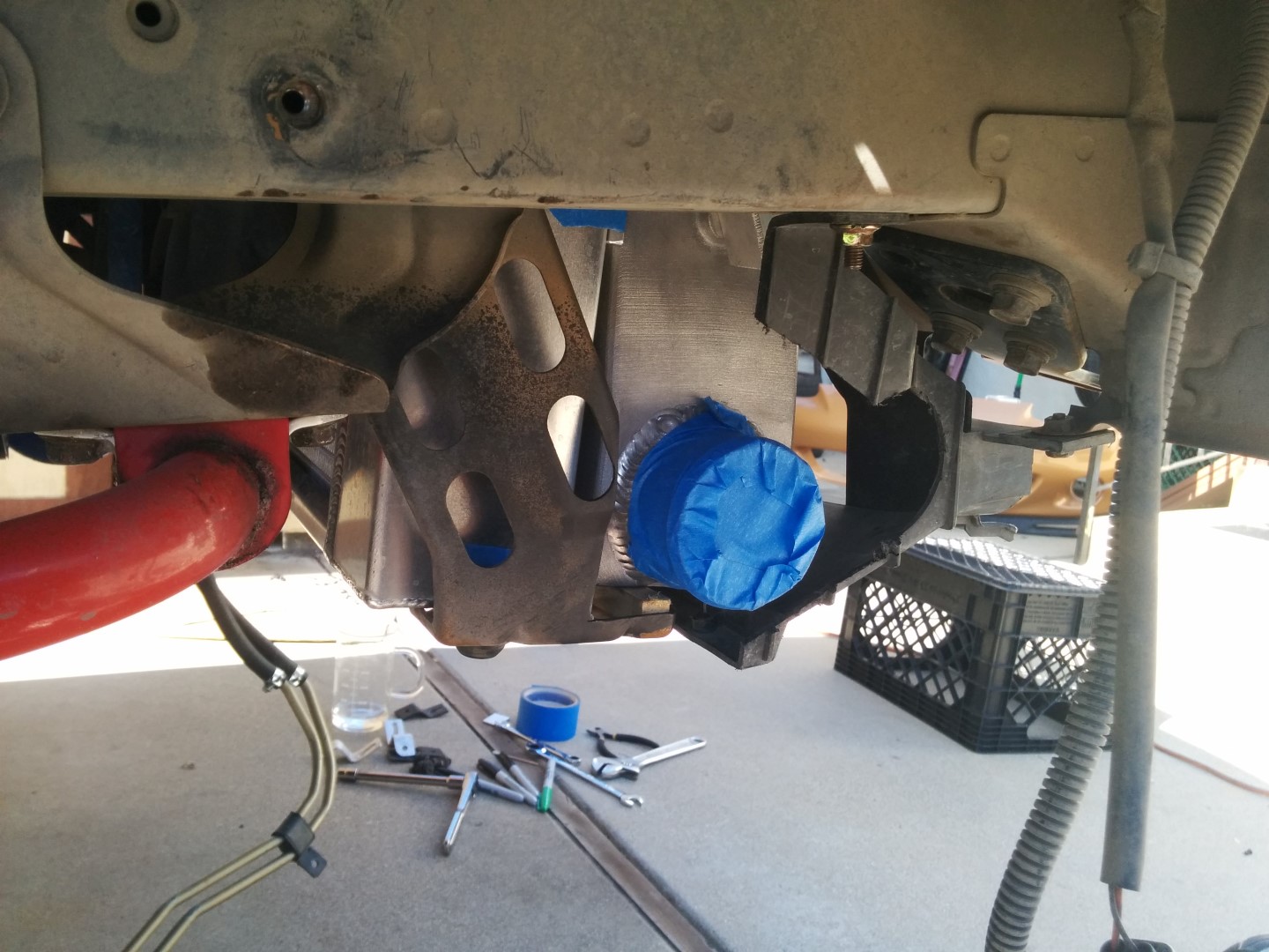
Upper mounting brackets nearly complete. I ended up cutting another .25" off the edge with the notch and slotting the holes for a little left/right adjustability.

Here is the tab and the top outside edge mount for the intercooler.
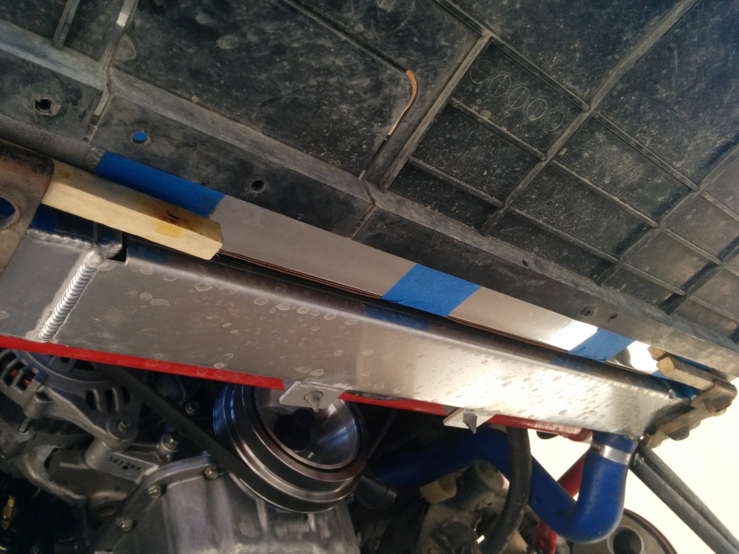
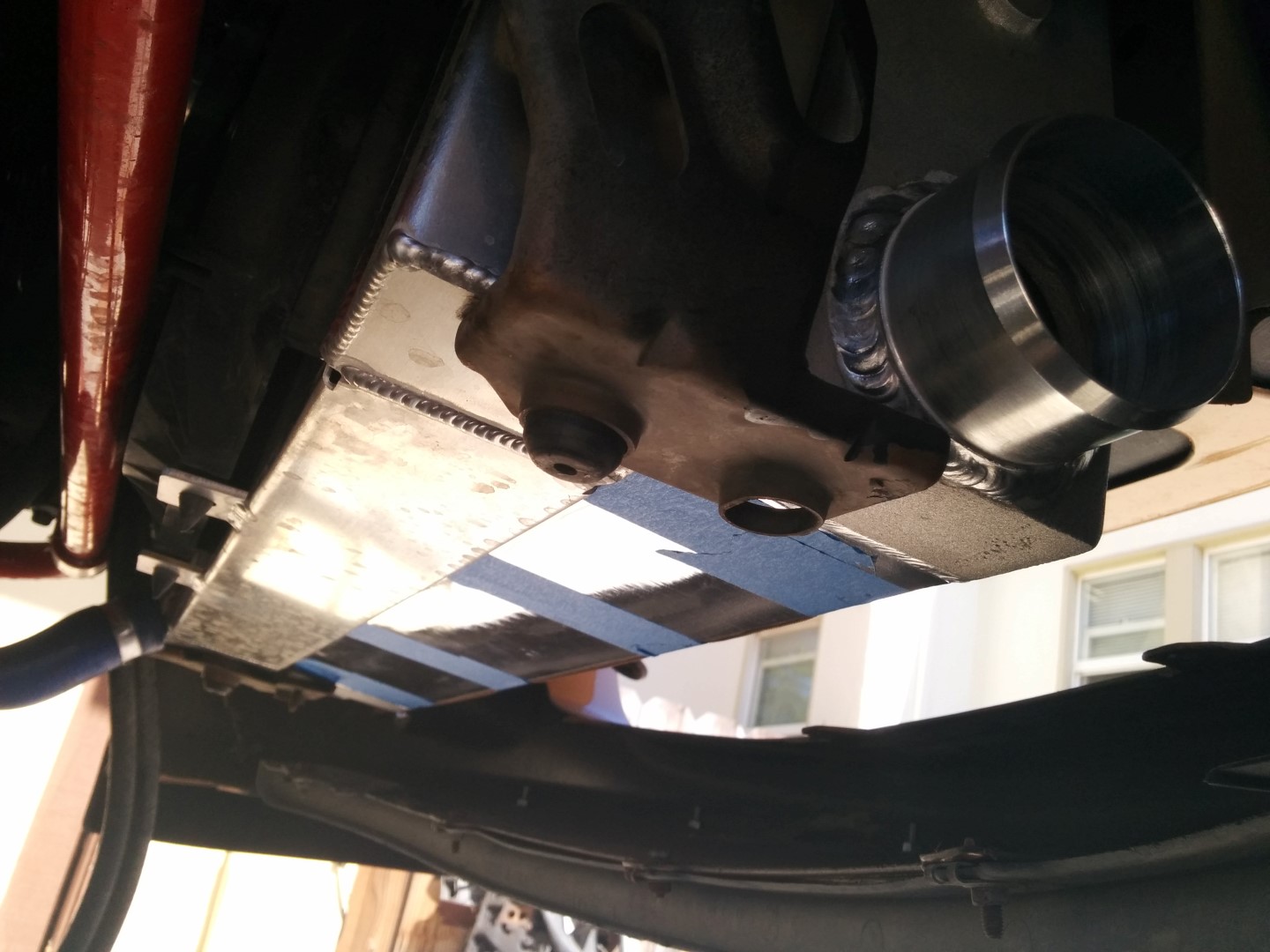
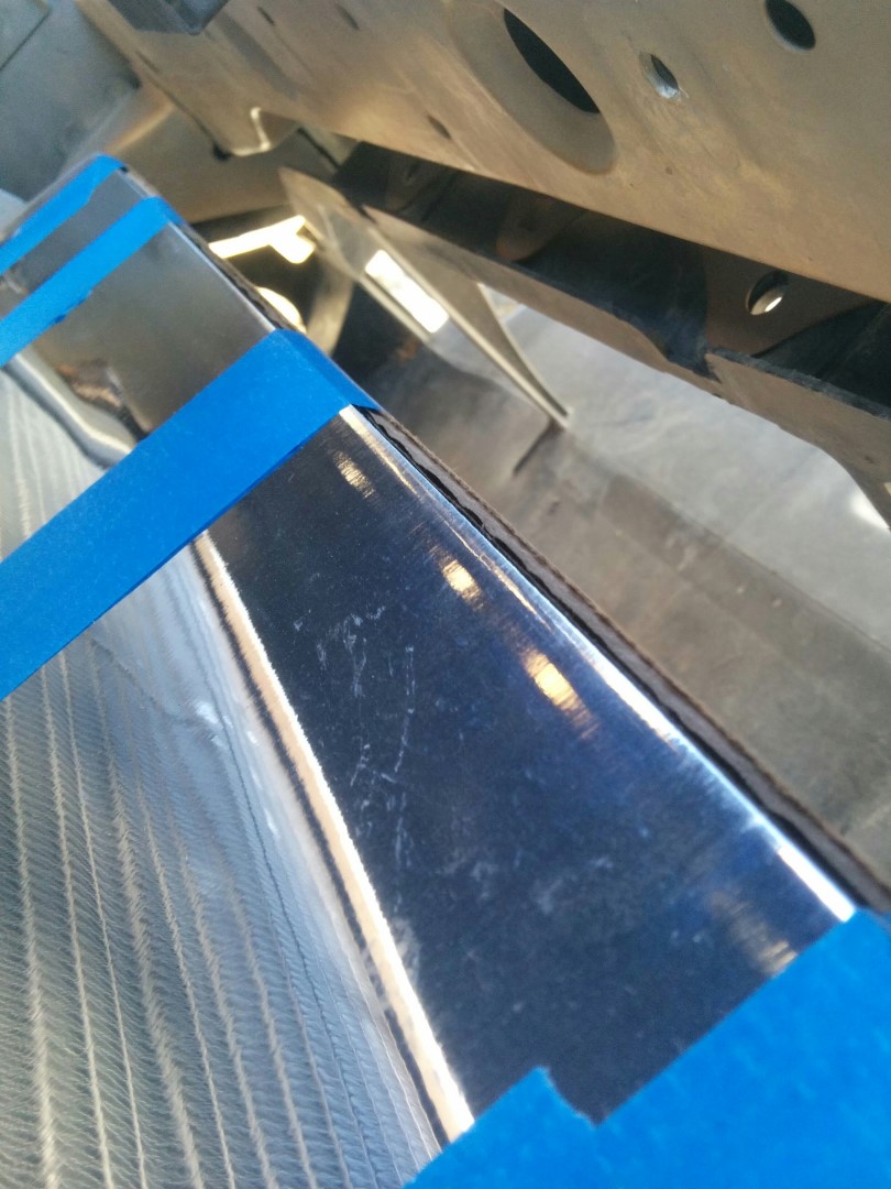
I spaced the intercooler up .5" from the top of the lower bracket, thus the square dowel. Not shown .25" spacer between the radiator and intercooler end tanks. More on this later.
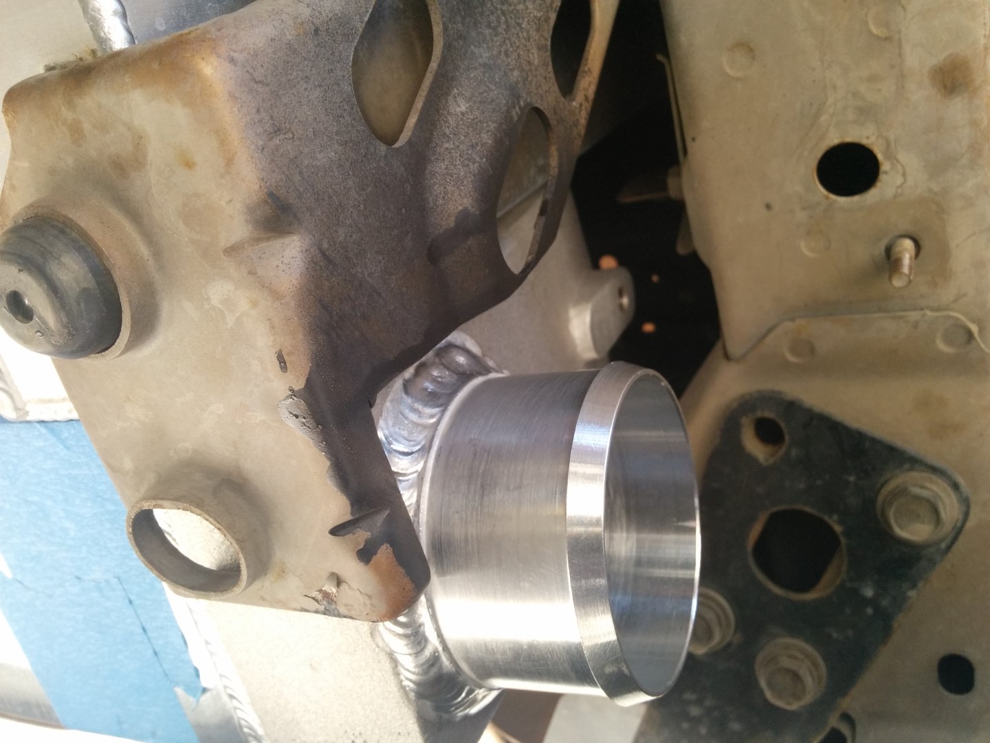
Boom! Upper mounting bracket.
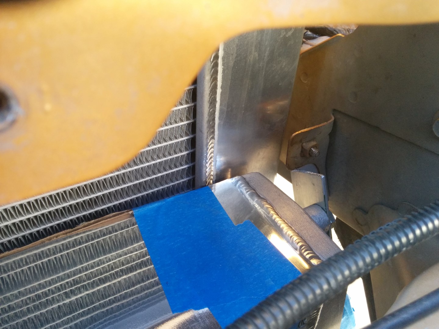
And here she is on the other side.
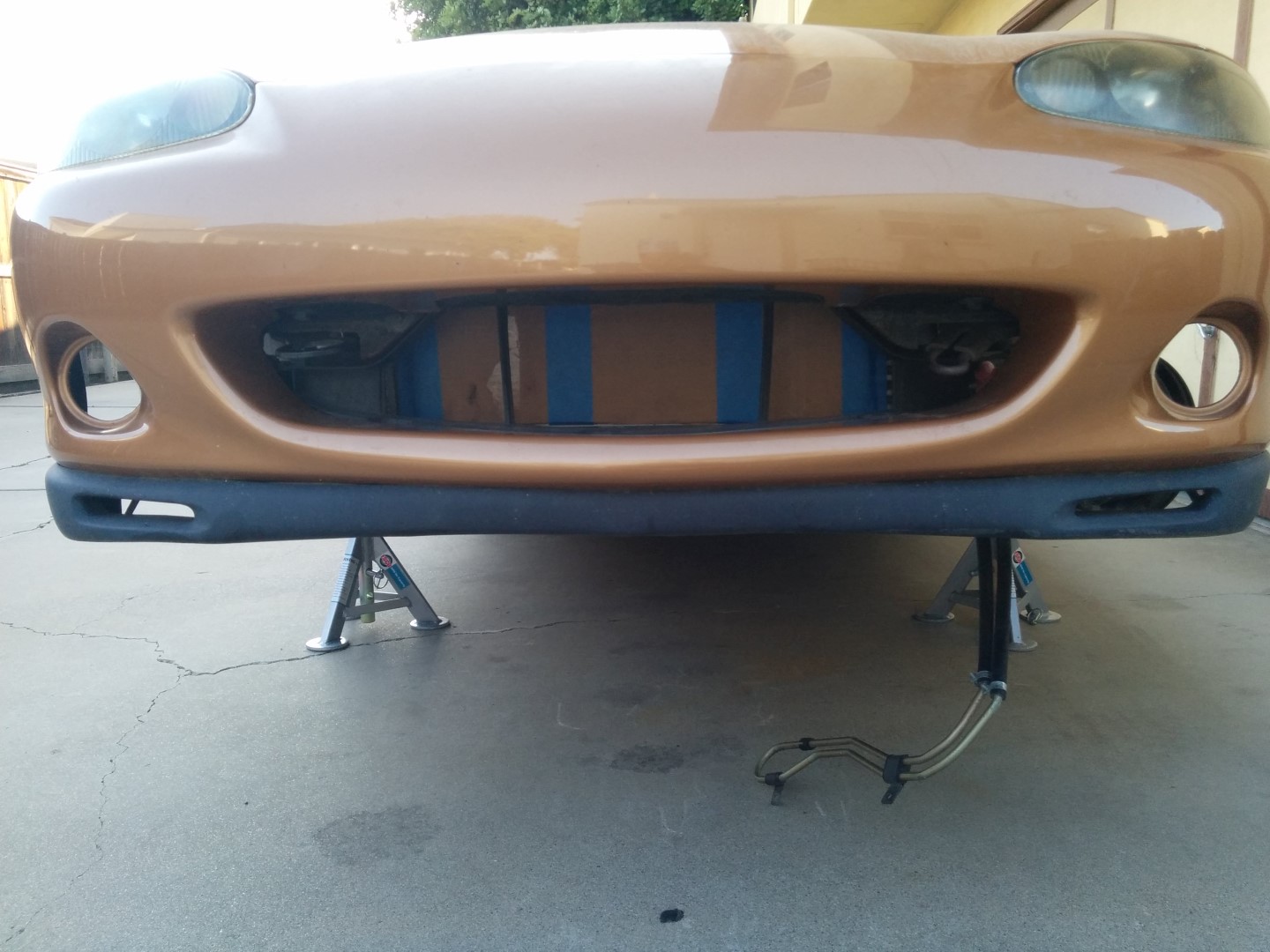
Here is the clearance between the factory front air guide and the intercooler core. Big bastard ain't it?
Oh yeah, did I mention I made the front air guide fit? I made the front air guide fit.
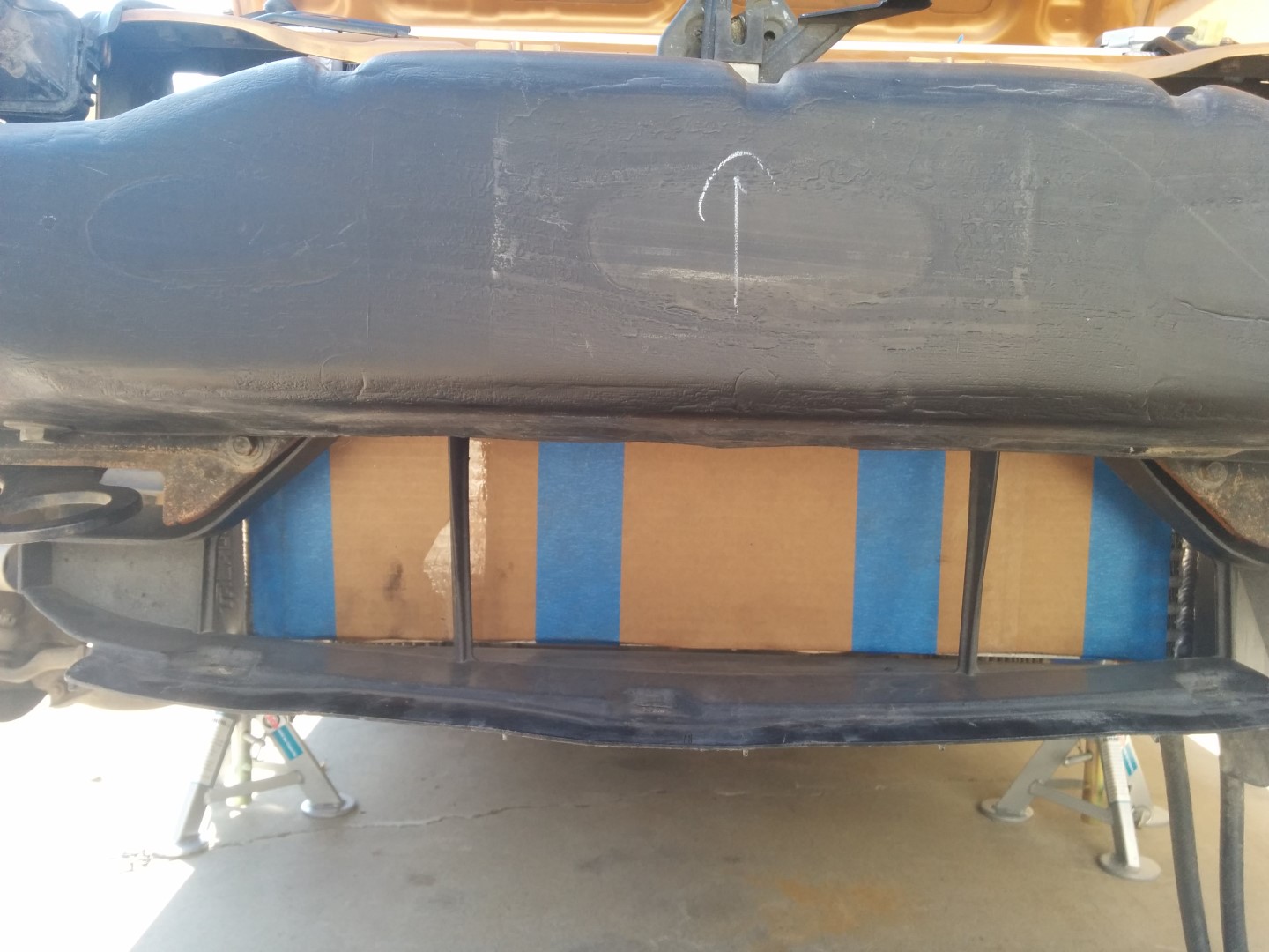
It actually fits quite well if I do say so myself.
This is the air guide I cut up for the Rotrex intercooler install. Obviously I need to close up the ends or replace it and cut up another one. Under-tray will need to be trimmed as well, the IC hits almost perfectly in the middle of where the tray and guide come together.
As to the lower mount, my intention is to replace the .5" square dowels with a T shaped stepped spacer spun up on the lathe and then welded to the bottom of the end tanks. After that, reuse the rubber lower mount from the AC condenser to keep them off the steel bracket, just like how the radiator mounts but smaller. This should provide plenty of support and allow a little movement while keeping it restrained. Hopefully I can convince Gesso to do the lathe and welding the next time I'm up at his place
On to the plumbing!
I'm going to follow the MSM routing on the drivers side in 2" pipe. The compressor to pipe connection will most likly be one of those hump connectors, so as to allow the engine to move a bit and not pull the plumbing apart.
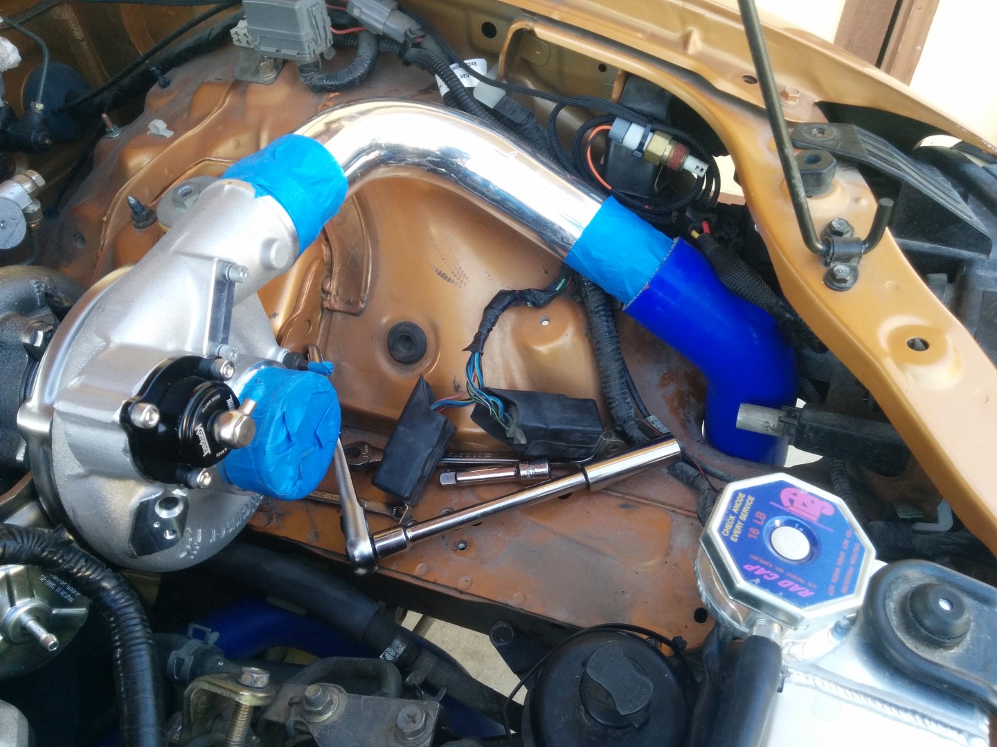
Another angle of the aluminum 90� going into the silicone 45� section. If I have time/inclination I'll build tabs to secure the tube.

Another 2" 90� and the silicone 45� section shown previously. I need another 45� and a joiner. I also need a 2.5" to 2" adapter for the end tank.
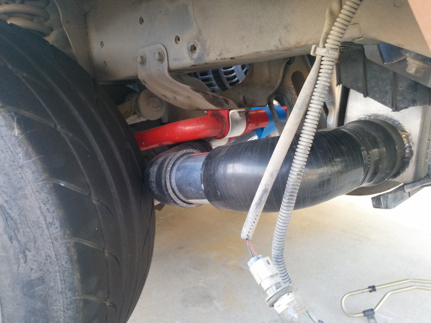
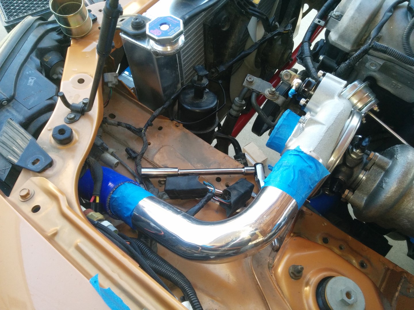
Passenger side is the traditional up from the bottom route because I don't feel like drilling a giant hole behind the headlight. Its currently plumbed in 2.25" and as you can see, I have a liiiiitle clearance problem. I'm using a 2.5" to 2.25" adapter at the end tank joined to the first silicone 90� section. I can save several inches at that connection by replacing those parts with a 2.5" to 2.25" silicone 90� converter. This will eliminate another joint and thus another point of failure. Yay!
I've certainly seen (and done) worse! All in all, solid progress. I'm super glad to be moving forward for once.
Step 1 was to do some cutting.
Chuck the intercooler up there and now there is clearance.
Looking up from the bottom you can just barely see the tab for the AC condenser mount. I plan on using this for the upper intercooler mount.
Upper mounting brackets nearly complete. I ended up cutting another .25" off the edge with the notch and slotting the holes for a little left/right adjustability.
Here is the tab and the top outside edge mount for the intercooler.
I spaced the intercooler up .5" from the top of the lower bracket, thus the square dowel. Not shown .25" spacer between the radiator and intercooler end tanks. More on this later.
Boom! Upper mounting bracket.
And here she is on the other side.
Here is the clearance between the factory front air guide and the intercooler core. Big bastard ain't it?
Oh yeah, did I mention I made the front air guide fit? I made the front air guide fit.
It actually fits quite well if I do say so myself.
This is the air guide I cut up for the Rotrex intercooler install. Obviously I need to close up the ends or replace it and cut up another one. Under-tray will need to be trimmed as well, the IC hits almost perfectly in the middle of where the tray and guide come together.
As to the lower mount, my intention is to replace the .5" square dowels with a T shaped stepped spacer spun up on the lathe and then welded to the bottom of the end tanks. After that, reuse the rubber lower mount from the AC condenser to keep them off the steel bracket, just like how the radiator mounts but smaller. This should provide plenty of support and allow a little movement while keeping it restrained. Hopefully I can convince Gesso to do the lathe and welding the next time I'm up at his place
On to the plumbing!
I'm going to follow the MSM routing on the drivers side in 2" pipe. The compressor to pipe connection will most likly be one of those hump connectors, so as to allow the engine to move a bit and not pull the plumbing apart.
Another angle of the aluminum 90� going into the silicone 45� section. If I have time/inclination I'll build tabs to secure the tube.
Another 2" 90� and the silicone 45� section shown previously. I need another 45� and a joiner. I also need a 2.5" to 2" adapter for the end tank.
Passenger side is the traditional up from the bottom route because I don't feel like drilling a giant hole behind the headlight. Its currently plumbed in 2.25" and as you can see, I have a liiiiitle clearance problem. I'm using a 2.5" to 2.25" adapter at the end tank joined to the first silicone 90� section. I can save several inches at that connection by replacing those parts with a 2.5" to 2.25" silicone 90� converter. This will eliminate another joint and thus another point of failure. Yay!
I've certainly seen (and done) worse! All in all, solid progress. I'm super glad to be moving forward for once.
Reply
0
0
08-31-2015, 12:47 AM
#1905
Elite Member
Thread Starter
iTrader: (37)
Join Date: Apr 2010
Location: Very NorCal
Posts: 10,441
Total Cats: 1,899
Thanks! Its temporary, plan is to replace it with gaffers tape for ALLOFIT
The factory guide is somewhat less than optimal, but for now its cheap and easy. I'll probably rivet some ABS to it to try to close up some of the gaps. Speaking of gaps, I need to come up with a clever way to seal the huge gaps around the sides of the radiator. I figured the TSE would have filled more of that space but it looks to be about .75" on both sides. Thats a lot of lost air that could be doing work.
Gotta remember to place the order with Silicone Intakes in the early AM.
Reply
0
0
 08-31-2015, 11:12 AM
#1907
Elite Member
Thread Starter
iTrader: (37)
Join Date: Apr 2010
Location: Very NorCal
Posts: 10,441
Total Cats: 1,899
Thanks! I think that's the 3rd revision with this combination? I decided not to show the other 3-4 sets of fail brackets
If I were to do this all over again (and I might) I would try to emulate the OEM condenser upper rubber mounts in order to avoid the upper hard mounts I had to make. I'm not sure the OEM ones could be reused because this IC is beastially heavy, but I do like the design. Another project for another time.
If I were to do this all over again (and I might) I would try to emulate the OEM condenser upper rubber mounts in order to avoid the upper hard mounts I had to make. I'm not sure the OEM ones could be reused because this IC is beastially heavy, but I do like the design. Another project for another time.
Reply
0
0
08-31-2015, 12:40 PM
#1908

My only concern is that I'd like to see a bit more air gap between the IC and radiator. I've always heard that heat exchangers should not touch. Having them that close might negatively affect both. Of course, this falls into the realm of "I heard on the internet" and might be complete BS, so . . . .
I'd like to see more aluminum tubing and fewer silicone joiners on a build of this caliber (see the psychological trick I'm trying to use there?). Takes a bit more time, but the end result is cleaner, space saving (might fix your tire rubbing issue) and eliminates joints. The pipe-expander + aluminum brazing method I was using worked out really well if you don't have easy access to someone that aluminum welds.
Jeffbucc has become suggestion-resistant lately. Let's see how I do here.
Reply
0
0
08-31-2015, 12:45 PM
#1909
SADFab Destructive Testing Engineer


iTrader: (5)
Join Date: Apr 2014
Location: Beaverton, USA
Posts: 18,642
Total Cats: 1,866
<p>He has master welder gesso at his service <img alt="Giggle" src="https://www.miataturbo.net/images/smilies/gay.gif" style="height:21px; width:15px" title="Giggle" /></p>
Reply
0
0
08-31-2015, 01:05 PM
#1911
Elite Member
Thread Starter
iTrader: (37)
Join Date: Apr 2010
Location: Very NorCal
Posts: 10,441
Total Cats: 1,899
Re air gap: I've got a .25" spacer in there right now between the IC and radiator. It will be removed and replaced with some sort of single sided door sealing sealing foam on the sides and bottom, top gap will be left open. My goal was to make sure they didn't actually contact but I have searched and searched and even asked here on the forum and couldn't get a straight answer as to HOW MUCH gap I actually need. We seem to have 40,000 intercooler threads but no real discussion about clearances, so I just decided to do my own thing.
The IC is going to heat soak with the engine off while the radiator ...radiates but I'm not sure how to solve that without radically changing the setup. I can push the IC out another .25" without too much issue, but I really want to use those lower condenser OEM mount points/rubbers. Beyond .5" and I have to re-engineer the lower mount.
Re silicone: Yes, there is a lot of it. The problem I'm running into is that the radius on the aluminum bends is way way way too wide to fit into most of these spaces. Right now I just need to get it built and functioning, I can redesign it later. I absolutely would like to have a minimum amount of silicone in the system, I promise.
Re Gesso: Who has already offered to tig it all in aluminum, but I'm not sure I can get all the bends and radii I want before this weekend. We have limited time and I don't want to monopolize it with intercooler plumbing. I will order all the parts, but it may not happen. I owe him some time on his projects as well. We both need to have our respective heaps up and running for M@MRLS in October.
Reply
0
0
 08-31-2015, 01:12 PM
#1915
Elite Member
Thread Starter
iTrader: (37)
Join Date: Apr 2010
Location: Very NorCal
Posts: 10,441
Total Cats: 1,899
Reply
0
0
08-31-2015, 01:32 PM
#1916
Elite Member
Join Date: Mar 2007
Location: Santa Clara, CA
Posts: 5,172
Total Cats: 856
I've actually been considering this, but based on prior experience there is no way in hell FM can get me that part before the weekend. FM makes great stuff, but their shipping is horribly slow and massively overpriced. The only place I've seen that's worse is BEGI. Now that I don't have AC that pipe would probably fit just fine. I may look for an aluminum 180� for that section for the future rebuild.
Well, this is me we are talking about
Well, this is me we are talking about
Almost everything I've ordered there ships out the following day (because I don't wake up early enough to call them before their UPS pickup). Brandon did warn me that they'd be doing inventory on Monday and that would delay shipping of my LS3 coil kit, though.
Combining replies:
A crutch for the 99%-ile FM customer who couldn't fab their way out of a cardboard box.

--Ian
Reply
0
0
08-31-2015, 01:59 PM
#1917
Elite Member
Thread Starter
iTrader: (37)
Join Date: Apr 2010
Location: Very NorCal
Posts: 10,441
Total Cats: 1,899
I can't find the post IC hose by itself on the website. The last time I purchased one I believe it was in the $75 range? Maybe more? I'm lazy but not that lazy. I'd rather spend the money on an IC pipe bead tool.
Reply
0
0
08-31-2015, 02:02 PM
#1918
SADFab Destructive Testing Engineer
iTrader: (5)
Join Date: Apr 2014
Location: Beaverton, USA
Posts: 18,642
Total Cats: 1,866
Reply
0
0
08-31-2015, 02:05 PM
#1920
Elite Member
Thread Starter
iTrader: (37)
Join Date: Apr 2010
Location: Very NorCal
Posts: 10,441
Total Cats: 1,899
<p></p><p>you're doin it wrong</p><p>DIY $5 charge pipe bead roller - D-series.org</p><p> </p>
Unrelated, thank you for changing your user icon. I started checking my notified threads yesterday and it was a sea of whatever kind of wiener that was. Bleh.
Reply
0
0


