The Portabull LFX Build
 01-22-2016, 05:50 PM
#21
Newb

Join Date: Jan 2016
Posts: 15
Total Cats: 0
This is a terrific build and one many will be following for sure, It will help me make up my mind as whether for the Ford Duratec, or this GM LLT/LFX route. I found an outfit in California that makes new harnesses for most newer Chevys they are called HotRodHarness in my search for various components to build a price list. They run around the $400+ for new harness with your plugs.

Reply
 0
0

0
02-07-2016, 07:21 PM
#23
Senior Member
Thread Starter

Join Date: May 2007
Location: Atlanta
Posts: 997
Total Cats: 156
I'm not so sure about that - there's a push-lock AN adapter for the NB that sucked, and that put a lot of FUD about the fittings. I've seen threads where people have complained, and when you look up the PN they used (if they mention it) they've used a 3/8ths instead of a 5/16ths adapter.
I need to throw together another update. We just finished up the cooling system (well, once the final radiator hose gets here), fabricated the ECU mount today, which means I can finally marry the miata and GM harnesses. And the hood has had a couple more hours of metalwork. And the intake is done. And the battery cables. Waiting on backordered low-pressure hose for the steering cooler.
I need to throw together another update. We just finished up the cooling system (well, once the final radiator hose gets here), fabricated the ECU mount today, which means I can finally marry the miata and GM harnesses. And the hood has had a couple more hours of metalwork. And the intake is done. And the battery cables. Waiting on backordered low-pressure hose for the steering cooler.
Reply
0
0
02-07-2016, 07:28 PM
#24
SADFab Destructive Testing Engineer


iTrader: (5)
Join Date: Apr 2014
Location: Beaverton, USA
Posts: 18,642
Total Cats: 1,866
You need the all aluminum ones. The push lock plastic ones suck.
The aluminum one threads in and works fine.
For the NA your best option is to cut and flare your hard-line.
Or run AN bulkhead connectors and skip the stock hard-line everywhere.
The aluminum one threads in and works fine.
For the NA your best option is to cut and flare your hard-line.
Or run AN bulkhead connectors and skip the stock hard-line everywhere.
Reply
0
0
02-12-2016, 12:10 PM
#25
Newb
Join Date: Jan 2016
Posts: 15
Total Cats: 0
I don't mean to hijack another web, but help is where you find it for fuel lines
Fuel Line Question - v8 Miata Forum - Home of the v8 Miata Conversion
Fuel Line Question - v8 Miata Forum - Home of the v8 Miata Conversion
Reply
0
0
02-12-2016, 03:46 PM
#26
Junior Member

Join Date: Feb 2016
Location: Livermore, CO
Posts: 193
Total Cats: 84
Man what I would give for that lift of yours! It is a SERIOUS pain to stab that LFX through the top by yourself!
Thanks for all of your help and input in your threads. It has made a world of difference on MANY occasions.
Between you and Carnut most of the basic build stuff is covered now.
Thanks for all of your help and input in your threads. It has made a world of difference on MANY occasions.
Between you and Carnut most of the basic build stuff is covered now.
Reply
0
0
02-12-2016, 10:42 PM
#28
Senior Member
Thread Starter
Join Date: May 2007
Location: Atlanta
Posts: 997
Total Cats: 156
We've had some cold weather here, and as everyone knows, busting a knuckle is thousand times worse when it's cold. And I really don't think we'd ever want to attempt this swap without a lift. Especially when you're test fitting everything multiple times, painting the underside with faux-lizardskin heatshielding, bending fuel line that needs to be checked a dozen times. Hell, I'm not sure if I even want to change brakepads without a lift anymore.
Plus you get to make stuff like this.

Those are some 4x4 fence posts cut to the width of the subframe on harbor freight dolly's. It's all screwed together with lag bolts and deck hardware - if I had to do it over again, I'd add another dolly on the front as we had a close call with the engine tipping forward without the transmission installed. But with this we could wheel the engine out of the way with relative ease. The added height of the fence posts allowed us to hit the subframe mounting points without needing to jack the subframe up while lowering the body down.
I've had a few people ask me about wiring - and I promise, I'll get to it - but it's a *major* job on this project and I want to make sure I've done it right before leading someone astray. Plus I have to grab all my notes and notebooks. The good news is that we finished up the coolant plumbing and intake, and this weekend is once again freezing, so I'll see if I can bang out a chapter.
Our todo list is now.. battery terminals, alternator wiring, ECU fusebox wiring, power steering plumbing, horns (putting in some buick horns, bye bye meep meep hello honk honk), instrument cluster, fluids, and running through everything with a torque wrench.
Plus you get to make stuff like this.
Those are some 4x4 fence posts cut to the width of the subframe on harbor freight dolly's. It's all screwed together with lag bolts and deck hardware - if I had to do it over again, I'd add another dolly on the front as we had a close call with the engine tipping forward without the transmission installed. But with this we could wheel the engine out of the way with relative ease. The added height of the fence posts allowed us to hit the subframe mounting points without needing to jack the subframe up while lowering the body down.
I've had a few people ask me about wiring - and I promise, I'll get to it - but it's a *major* job on this project and I want to make sure I've done it right before leading someone astray. Plus I have to grab all my notes and notebooks. The good news is that we finished up the coolant plumbing and intake, and this weekend is once again freezing, so I'll see if I can bang out a chapter.
Our todo list is now.. battery terminals, alternator wiring, ECU fusebox wiring, power steering plumbing, horns (putting in some buick horns, bye bye meep meep hello honk honk), instrument cluster, fluids, and running through everything with a torque wrench.
Reply
0
0
02-13-2016, 07:28 AM
#29
Junior Member

Join Date: Jan 2016
Posts: 55
Total Cats: 5
When you were test fitting the engine, did the left side scrape really hard or just not fit. I don't have a lift and this going to be tough with a lot of trial and error. Without a lift, the strategy will be to drop the engine in with the lower suspension cradle lowered and bring the cradle up after the engine is down. It's a headache, but I've done it before that way on 99 vette.
With all the sledge hammer engineering to the firewall, how much clearance is left on the inside to the heater core? I thought it was tight to begin with.
With all the sledge hammer engineering to the firewall, how much clearance is left on the inside to the heater core? I thought it was tight to begin with.
Reply
0
0
02-13-2016, 05:33 PM
#30
Senior Member
Thread Starter
Join Date: May 2007
Location: Atlanta
Posts: 997
Total Cats: 156
I don't envy you coming from the top - Carnut might be able to give you some guidance there. When we lowered the body, we had to position the engine forward of the firewall, bring the body to just above the studs near the upper control arms till they would almost touch, then push the engine back and lower the body down the rest of the way. The back of the drivers side cylinder head would touch the firewall without the pocket, and the subframe mounts weren't square (front subframe stud would meet, but the rear stud had a gap of 1/8 - 1/4in and the engine would be tilted forward by the motor mounts.)
So.. Scrape. It'll fit, but it won't fit right - I wouldn't want to run the studs up all the way.
We cut our heatercore lines and ran new aluminum lines. I'll hit this bit up in the cooling chapter.

So.. Scrape. It'll fit, but it won't fit right - I wouldn't want to run the studs up all the way.
We cut our heatercore lines and ran new aluminum lines. I'll hit this bit up in the cooling chapter.
Reply
0
0
02-14-2016, 07:45 PM
#31
Junior Member
Join Date: Feb 2016
Location: Livermore, CO
Posts: 193
Total Cats: 84
Cujoel,
I think I recall seeing gooflophaze mention it in one of his posts but grind off as much of the inside edge of the engine bay as you can but not into the seam welds. If you are going in from the top by yourself it will make life MUCH easier to have that little extra space.
I have had the LFX in and out 3 times now and the way you described with the vette is how I have done it each time. I figure I will drop my process in your thread so others without a lift can benefit from my trial and error.
A small 4 wheel cart under the middle of the subframe and loosen the 6 bolts so the subframe is just barely attached. ( I tried just using the struts to keep the subframe in place but it turned out to be a bigger pain.)
Pull the 4 bolts that hold the NB rack so it can be lowered out of the way.
Engine on the lift and with the car on the wheels and stab the motor and trans working it slowly down and back
An additional small 4 wheel cart is a BIG help on the tail of the trans so it moves back easier.
You will hit the point where the engine will not fit between the subframe and the firewall thanks to the oil pan hitting the subframe. When you hit that point remove the 6 bolts that hold up the subframe so that it is now just resting on the cart.
jack the body up about 4-6" and the motor will slide into place.
Lower the motor to the subframe and attach the motor to the subframe. (I have tried both ways and found that having the engine mounts attached to the subframe first and then once you lower the motor into place just dropping in the 6 bolts to the motor was MUCH easier. I have thrown out many LOUD and intense profanities trying to line up those two engine mount bolts the other way.)
Lower the body back down on the subframe and bolt it up.
I think if you were to get the modified oil pan from V8R you may not need to drop the subframe but I spent the money elsewhere.
Hopefully this makes sense and it will help someone else.
Reply
0
0
02-15-2016, 10:31 AM
#32
Newb
Join Date: Jan 2016
Posts: 15
Total Cats: 0
Griff, so does the oil pan just fit between the cross member? and are you stiil able to clear the rack and keep the engine level and low enough? I am not concerned at all about the hood and I will remove the bracing where needed and "blister" the hood. Also, I have done the V8 install and in that case, the rear firewall area does have to be messaged a bit and trimming the edge bracing as well. I did not have to hammer much as I used a t-5 for the trans
Reply
0
0
02-15-2016, 10:57 AM
#33
Junior Member
Join Date: Feb 2016
Location: Livermore, CO
Posts: 193
Total Cats: 84
Miles,
I have NOT been able to fit the factory pan past the rack or the subframe with the subframe bolted up. I have had to lift the body up about 4" off the subframe to get the motor to clear everything and slide back into place. Not hard to do but time consuming if you are by yourself.
I would love to know if a modified V8R pan avoids dropping the subframe because it just may make it worth it to some folks.
I find this the most interesting comment so far though:
"and the subframe mounts weren't square (front subframe stud would meet, but the rear stud had a gap of 1/8 - 1/4in and the engine would be tilted forward by the motor mounts."
My car was the exact same way and it forced me to take a 30 minute sanity break the first time I put the motor in. Seeing that you had the same issue makes me feel a bit better I guess but it appears that V8R may be off on a measurement or two.
I hope you don't mind me dropping these in here Gooflophaze. I did not plan to do another build thread for mine since you and Carnut have done such an amazing job already documenting the process with outstanding photos.
Last edited by griff; 02-15-2016 at 11:48 AM.
Reply
0
0
02-15-2016, 11:29 AM
#34
Bannisheded

Join Date: Jun 2008
Location: Senatobia, MS
Posts: 165
Total Cats: -1
We've had some cold weather here, and as everyone knows, busting a knuckle is thousand times worse when it's cold. And I really don't think we'd ever want to attempt this swap without a lift. Especially when you're test fitting everything multiple times, painting the underside with faux-lizardskin heatshielding, bending fuel line that needs to be checked a dozen times. Hell, I'm not sure if I even want to change brakepads without a lift anymore.
Plus you get to make stuff like this.
Those are some 4x4 fence posts cut to the width of the subframe on harbor freight dolly's. It's all screwed together with lag bolts and deck hardware - if I had to do it over again, I'd add another dolly on the front as we had a close call with the engine tipping forward without the transmission installed. But with this we could wheel the engine out of the way with relative ease. The added height of the fence posts allowed us to hit the subframe mounting points without needing to jack the subframe up while lowering the body down.
I've had a few people ask me about wiring - and I promise, I'll get to it - but it's a *major* job on this project and I want to make sure I've done it right before leading someone astray. Plus I have to grab all my notes and notebooks. The good news is that we finished up the coolant plumbing and intake, and this weekend is once again freezing, so I'll see if I can bang out a chapter.
Our todo list is now.. battery terminals, alternator wiring, ECU fusebox wiring, power steering plumbing, horns (putting in some buick horns, bye bye meep meep hello honk honk), instrument cluster, fluids, and running through everything with a torque wrench.
Reply
0
0
02-15-2016, 01:00 PM
#35
Newb
Join Date: Jan 2016
Posts: 15
Total Cats: 0
Griff, I have not seen the LS pan, only photos, but is is considerably longer from the LFX I would guess. They do according to photos cut a portion of the pan back to what appears to be 6-8 inches. Partly I think is because of its length plus depth. My 302 ford was cut just behind where the oil pump is located and gave good clearance. I placed my engine about 1/2 inch from the firewall and not closer. You are correct about the mounts as I made my own, and adjusted the several times in all directions to get them where I needed them to be. I am not too sure how accurate mounting the engine to the subframe approach workd out..if you are luck it might be close enough
Reply
0
0
02-15-2016, 01:31 PM
#36
Junior Member
Join Date: Feb 2016
Location: Livermore, CO
Posts: 193
Total Cats: 84
I'm not so sure about that - there's a push-lock AN adapter for the NB that sucked, and that put a lot of FUD about the fittings. I've seen threads where people have complained, and when you look up the PN they used (if they mention it) they've used a 3/8ths instead of a 5/16ths adapter.
I need to throw together another update. We just finished up the cooling system (well, once the final radiator hose gets here), fabricated the ECU mount today, which means I can finally marry the miata and GM harnesses. And the hood has had a couple more hours of metalwork. And the intake is done. And the battery cables. Waiting on backordered low-pressure hose for the steering cooler.
I need to throw together another update. We just finished up the cooling system (well, once the final radiator hose gets here), fabricated the ECU mount today, which means I can finally marry the miata and GM harnesses. And the hood has had a couple more hours of metalwork. And the intake is done. And the battery cables. Waiting on backordered low-pressure hose for the steering cooler.
Reply
0
0
02-15-2016, 04:12 PM
#37
Senior Member
Thread Starter
Join Date: May 2007
Location: Atlanta
Posts: 997
Total Cats: 156
I'll write up the cooling bit tonight. It'll be a doozy.
But I can write up the oil pan real quick.
The oil pan on the LFX is the lowest point on the car, and the modified oil pan.. is really just 3/4in shorter.
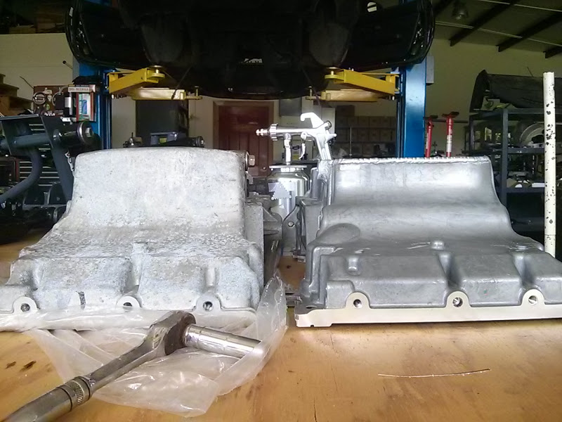
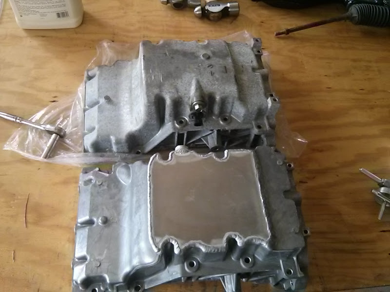
It also deletes the low oil sensor bung, and moves the oil drain plug to the other side.

To install the pan, the engine needs to be on an engine stand. So you'll need to find some long-ish M12x1.5 (todo verify this) bolts to pop on the stand. I think I used old Xterra head bolts from my brothers car. You can see there are 3 bolts that run along the front of the pan that go to the timing cover, and to get to the middle one you'll have to pull the harmonic damper.
We tried to sneak it past. No go. And none of our standard pullers worked (which is a shame because we have a plethora of them, just too large), so we had to run out to NAPA real quick and grab one. This one worked like a champ.
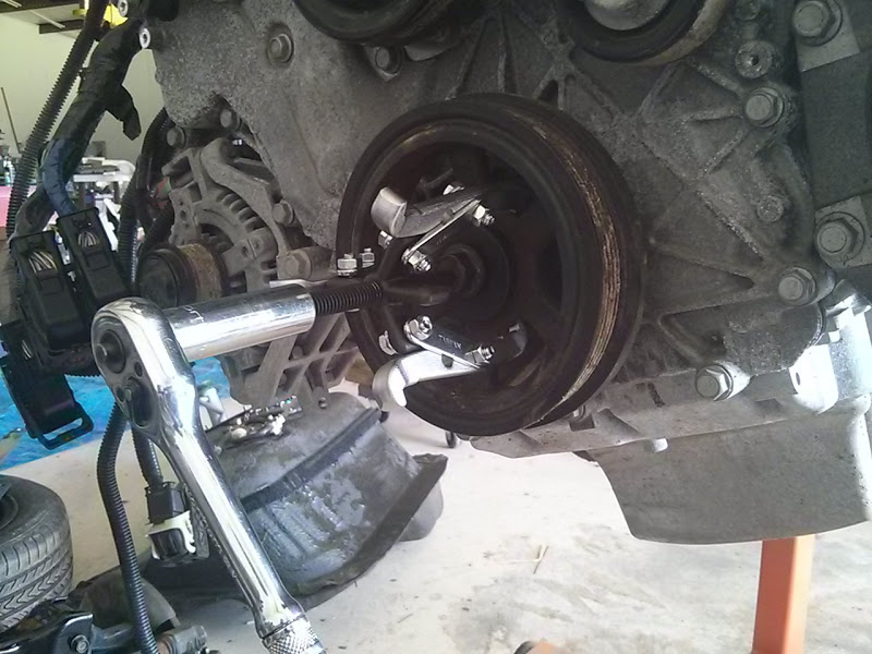
You'll also need to pick up a new crank pulley bolt, as the bolt is torque to yield. Torque spec is 74ft/lbs, then 150 degrees. We had to wait until the transmission, brakes, and parking brakes were put back in to stop the motor from turning. The 2 piece flywheel also fought us while torquing this bolt, as you'd have to take up.. 45-60 degrees of wrench travel just taking up the slack in the clutch. With a breaker bar and jack handle slipped over as a cheater bar, I'd say I was probably putting 150ft - 200ft/lbs on the bolt. We had to disconnect the sway bar from the body to get clearance. The bolt is only $5 from GM, and it's PN 11569873.
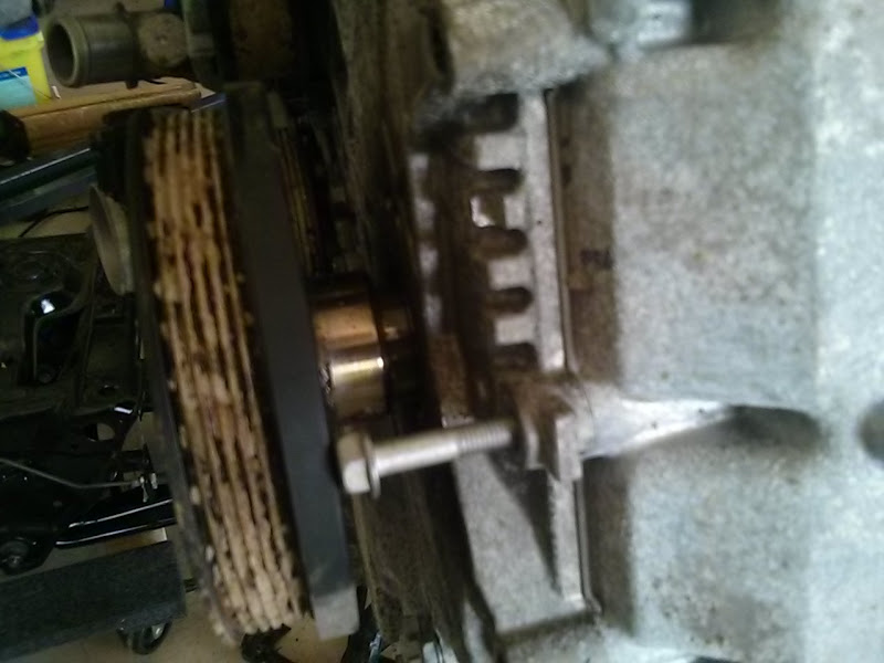
With the bolts out, we popped the oil pan off. There are 2 slots big enough to fit a pry bar that won't mar the pan too badly.

And finally you can look up her skirt.
Since our engine only had 7k miles, we didn't feel any need to inspect the bearings. I wish I had gotten a picture of the faceted grinds on the crank weights. I didn't take many pictures after this as my hands were dirty from cleaning oil and scraping the old gasket material off - which is straightforward razorblades and brake clean. Pay special attention to the timing cover, as you don't want to remove too much of the gasket material where block and oil pan meet. The v8r pan came with new bolts (not really necessary) and tube of GM gasket maker.
I believe GM assembled the oil pan to the block then mounted the timing cover - because you'll have to wedge the oil pan forward to the timing cover then down to the block, making sure you'll hit the 2 alignment pins on the passenger side. This is annoying because the wedge move will scrape some of the gasket material off the timing cover face. We ended up with a small oil leak at the front I was (hopefully) successful in scabbing over with gray RTV. With everything on, we did what I was taught - or maybe mistaught - tightened all the bolts on the oil pan in an X formation to let the RTV squish, then loosed them for the RTV to set, then tightened them back down to give the RTV a more mechanical force. (Note: what I was taught - black (adhesive) RTV is torque once and done. Gray RTV is rigid and can be more mechanical). Torque spec is 89in/lbs, so just "snug".

You can see the oil leak on the right side. Successfully scabbed over (I hope).

Now, things that I didn't do that I still might - see the casting dimple in the front middle? It almost touches the steering rack body. I'll have to inspect it once we drive the car some, and I might have to pull the 4 bolts for the rack and swing it out of the way to hit the nub with a die grinder. Just a smidge, you can see in the photo it's a bolt hole for the windage tray.
But I can write up the oil pan real quick.
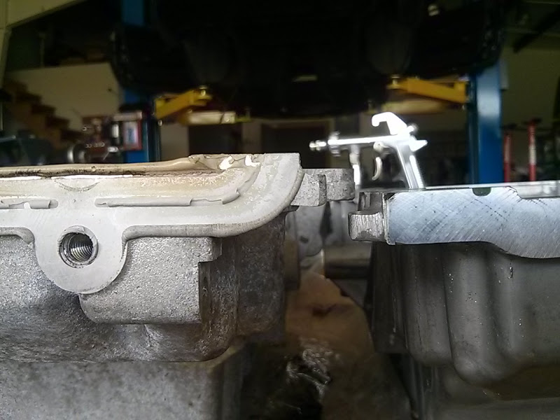
The oil pan on the LFX is the lowest point on the car, and the modified oil pan.. is really just 3/4in shorter.
It also deletes the low oil sensor bung, and moves the oil drain plug to the other side.
To install the pan, the engine needs to be on an engine stand. So you'll need to find some long-ish M12x1.5 (todo verify this) bolts to pop on the stand. I think I used old Xterra head bolts from my brothers car. You can see there are 3 bolts that run along the front of the pan that go to the timing cover, and to get to the middle one you'll have to pull the harmonic damper.
We tried to sneak it past. No go. And none of our standard pullers worked (which is a shame because we have a plethora of them, just too large), so we had to run out to NAPA real quick and grab one. This one worked like a champ.
You'll also need to pick up a new crank pulley bolt, as the bolt is torque to yield. Torque spec is 74ft/lbs, then 150 degrees. We had to wait until the transmission, brakes, and parking brakes were put back in to stop the motor from turning. The 2 piece flywheel also fought us while torquing this bolt, as you'd have to take up.. 45-60 degrees of wrench travel just taking up the slack in the clutch. With a breaker bar and jack handle slipped over as a cheater bar, I'd say I was probably putting 150ft - 200ft/lbs on the bolt. We had to disconnect the sway bar from the body to get clearance. The bolt is only $5 from GM, and it's PN 11569873.
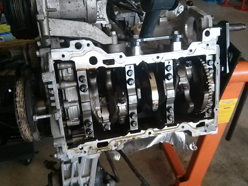
With the bolts out, we popped the oil pan off. There are 2 slots big enough to fit a pry bar that won't mar the pan too badly.
And finally you can look up her skirt.
Since our engine only had 7k miles, we didn't feel any need to inspect the bearings. I wish I had gotten a picture of the faceted grinds on the crank weights. I didn't take many pictures after this as my hands were dirty from cleaning oil and scraping the old gasket material off - which is straightforward razorblades and brake clean. Pay special attention to the timing cover, as you don't want to remove too much of the gasket material where block and oil pan meet. The v8r pan came with new bolts (not really necessary) and tube of GM gasket maker.
I believe GM assembled the oil pan to the block then mounted the timing cover - because you'll have to wedge the oil pan forward to the timing cover then down to the block, making sure you'll hit the 2 alignment pins on the passenger side. This is annoying because the wedge move will scrape some of the gasket material off the timing cover face. We ended up with a small oil leak at the front I was (hopefully) successful in scabbing over with gray RTV. With everything on, we did what I was taught - or maybe mistaught - tightened all the bolts on the oil pan in an X formation to let the RTV squish, then loosed them for the RTV to set, then tightened them back down to give the RTV a more mechanical force. (Note: what I was taught - black (adhesive) RTV is torque once and done. Gray RTV is rigid and can be more mechanical). Torque spec is 89in/lbs, so just "snug".
You can see the oil leak on the right side. Successfully scabbed over (I hope).
Now, things that I didn't do that I still might - see the casting dimple in the front middle? It almost touches the steering rack body. I'll have to inspect it once we drive the car some, and I might have to pull the 4 bolts for the rack and swing it out of the way to hit the nub with a die grinder. Just a smidge, you can see in the photo it's a bolt hole for the windage tray.
Last edited by gooflophaze; 02-15-2016 at 05:40 PM.
Reply
0
0
02-15-2016, 05:07 PM
#39
Senior Member
Thread Starter
Join Date: May 2007
Location: Atlanta
Posts: 997
Total Cats: 156
Thanks, one of the hats I wore at my previous job was as a technical writer. I'll go ahead and borrow from that experience and say feel free to ask questions / clarifications, because the only way documentation improves is by people asking. It's also why I sprinkle "todo" throughout the writing, as eventually I'll have my notebooks beside me and I can look up the thread pitch / pn.
Reply
0
0


