
The Definitive "VVT swap into 90-97 chassis" Megathread.
 04-06-2015, 07:28 PM
#121
Junior Member

Join Date: Jul 2009
Location: Orange County, CA
Posts: 419
Total Cats: 45
I used the wiring from the pressure up solenoid in for my VVT solenoid (see earlier responses). I did it because the pressure up solenoid (a switched 12v+ and trigger) was already a part of the injector wiring harness. I just added the VVT pigtail to the existing wiring and moved the trigger wire on the ECU side (AEM EMS). It was a lot easier than having to patch into the 12v+ from the injectors and run a new trigger.
Is there anything similar I can use for the knock sensor? Maybe the unused factory O2 plug? Or one of the EGR plugs? Will investigate...

Reply
 0
0

0
04-07-2015, 12:36 PM
#122
Elite Member
iTrader: (15)

Join Date: Jan 2007
Location: Murfreesboro,TN
Posts: 2,043
Total Cats: 265
With the AEM I just moved the pin from one spot in the ECU plug to another (I think they are in the same plug). Just buy a tool to remove the pins and its makes life much easier.
Reply
0
0
04-12-2015, 09:29 PM
#123
Junior Member

Join Date: Mar 2010
Location: Melissa, TX
Posts: 172
Total Cats: 20
How exactly did you get this to work?
I ripped apart the Fuel rail harness the motor came with since it came with both sides of the 8 pin connector. Patched in my two coolant temperature sensors into this connector (1 2 pin sensor and 1 1 pin sensor in place of the 2004 3 pin sensor) with the intention of redoing the mating side. I figured I might as well leave the other 5 pins alone so that I can do sequential fuel injection and have a handy disconnect for removing the motor. However
I forgot to request that my MSLabs MS3 basic to have sequential fueling outputs. DOH. I guess I will just patch the chassis side of the cable to split out the 1/4 and the 2/3 signals to each individual injector, and run the extra wires in the bundle so that if I ever decide that I need it, I will just need to remove the jumper in the harness and do a bit of work on the ECU.
Also after seeing how the spark plug condensor and ground were run, I disliked it immensely. The condenser and ground are hooked up by running out the spark plug harness connector, back into a 4 pin connector at the front of the motor that is bundled with the FI harness and mounted at the rear of the motor. The condensor is supposed to help with voltage drop, why would you hang it off an unnecessarily long length of cable?!? Tore this apart and patched the condensor connector and the grounds directly into the injector harness, eliminating the 4 pin connector at the front of the motor, so now all that is up there is the 8 pin Fuel injector connector and the 2 pin knock sensor connector on the left and the Crank angle sensor connector on the right.
Reply
0
0
04-12-2015, 10:49 PM
#124
Cpt. Slow

iTrader: (25)
Join Date: Oct 2005
Location: Oregon City, OR
Posts: 14,189
Total Cats: 1,135
The timing wheel is just a disc, it can be removed and bolted in behind the 1.6 wheel, I'm assuming. It comes off after the 4 m6 bolts are removed.
All MS3s have sequential injection as far as I know, but if you order it in batch, Rev will jumper them together and send a batched base map. A few jumper changes and wiring changes, and you'll be set for sequential.
All MS3s have sequential injection as far as I know, but if you order it in batch, Rev will jumper them together and send a batched base map. A few jumper changes and wiring changes, and you'll be set for sequential.
Reply
0
0
04-17-2015, 08:32 PM
#126
Junior Member
Join Date: Mar 2010
Location: Melissa, TX
Posts: 172
Total Cats: 20
Well. I discovered something else. 1.6 alternator, or 1.8, you will need the alternator bracket from a 1994 or later. The 1.6L bracket wont fit, interferes with the mount point for the 1994+ bracket on the water pump...
Reply
0
0
04-20-2015, 04:00 PM
#132
Junior Member
Join Date: Mar 2010
Location: Melissa, TX
Posts: 172
Total Cats: 20
Moving along. For the purpose of documentation, the Reverent MSLabs MS3 basic does support sequential injectors out of the box, however it will not be wired to the DB-37 unless requested, which I neglected to do. If one were to desire to hook them up the following changes would need to be made:
I am already buying pins and tools to service the ECU connector because one of the wires was messed up when I removed the ECU (details here: https://www.miataturbo.net/meet-gree...-rescue-79959/) so I will probably be hooking this up.
Next up:
Looking for an answer on this from Reverant for using one of his MS3 Basic PNPs for a 90-93. I suspect that I would have to purchase a middle connector for the ECU and add wires to it as if it was for a 1994-1997. On the middle connector pin "I" would be the 5V reference, On "F" would be the signal, and pin "O" would serve as ground.
Otherwise (if not requested), they can be brought out of the main connector (but you first need to place a jumper on header JP11, and move the jumper on header JP10 from 1-2 to 2-3
Injector 1 goes to pin 2U
Injector 2 goes to pin 2V
Injector 3 goes to pin 2Y
Injector 4 goes to pin 2Z
Injector 1 goes to pin 2U
Injector 2 goes to pin 2V
Injector 3 goes to pin 2Y
Injector 4 goes to pin 2Z
Next up:
TPS:
The 90-93 manual chassis did not originally come with a 0-5v variable TPS. To use a 94-05 0-5v throttle position sensor in a 90-93 chassis, consult with your ECU supplier to confirm the wiring changes that are necessary.
The 90-93 manual chassis did not originally come with a 0-5v variable TPS. To use a 94-05 0-5v throttle position sensor in a 90-93 chassis, consult with your ECU supplier to confirm the wiring changes that are necessary.
Reply
0
0
04-20-2015, 05:44 PM
#133
Junior Member
Join Date: Mar 2010
Location: Melissa, TX
Posts: 172
Total Cats: 20
Nope. Much easier Than that per the man himself. For MS labs MS3 Basic 90-93 PNP:
Make sure the pull the fuse as specified in the directions.
No, you'll be using the stock TPS wiring instead:
- Red: 5V
- Black/Light Green: Ground
- Green/White: Signal.
- Red: 5V
- Black/Light Green: Ground
- Green/White: Signal.
Last edited by Ziggo; 04-20-2015 at 11:11 PM.
Reply
0
0
04-22-2015, 10:50 AM
#134
Junior Member

Join Date: Mar 2012
Location: Portugal
Posts: 200
Total Cats: -12
I ordered the 99-00 fuel rail from a scrappy expecting it to only have a fuel damper on the return end. But it came with a fuel pressure valve and return, and doesn't use fittings for the fuel pipes (it's clamp and hose). Otherwise it looks exactly like the 99-00.
It mated to the VVT engine, only needed to slightly bend the inlet pipe for it to clear the timing belt cover. I'm guessing it will work but I'm curious... If this is not an 99-00 rail, which one is it?
So... What have I been sent, do you guys have an idea?
Getting pics as soon as I get out from work.
Reply
0
0
 04-22-2015, 01:51 PM
#136
Junior Member
Join Date: Mar 2012
Location: Portugal
Posts: 200
Total Cats: -12
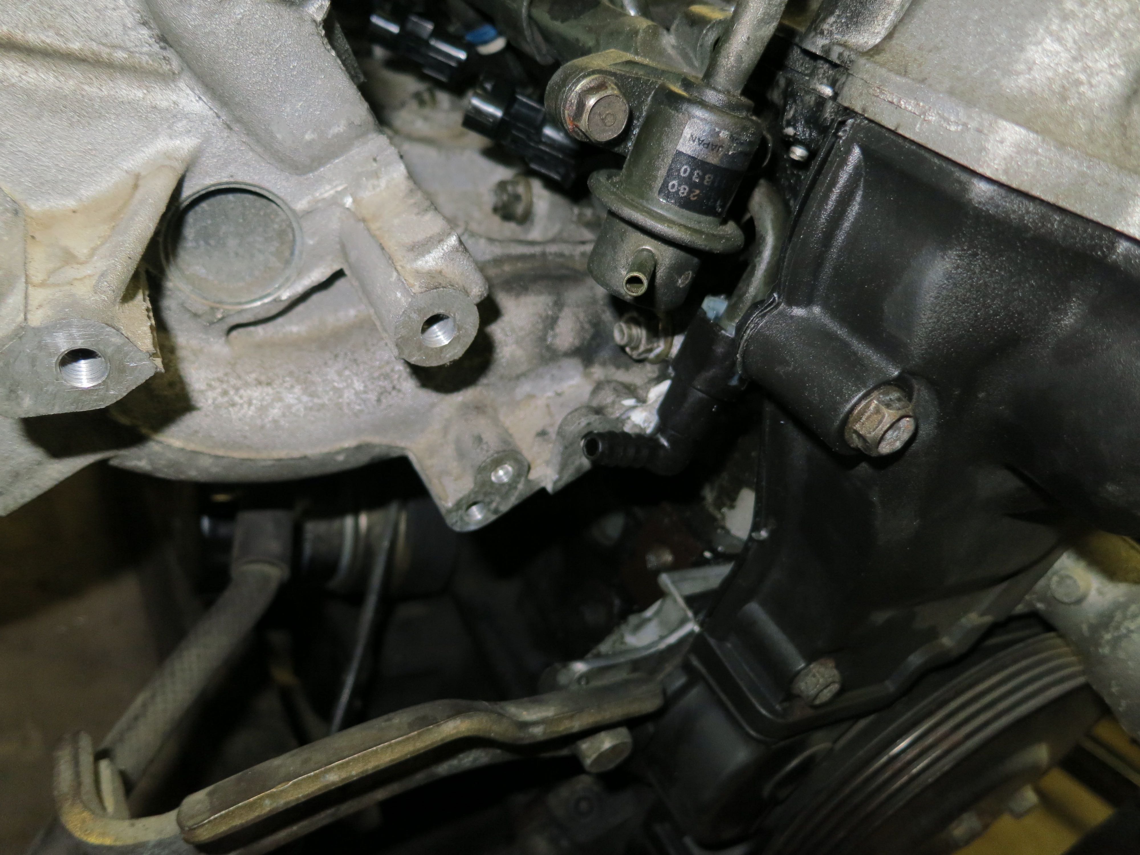
Don't really know, but it mounts perfectly to the engine and the FPR return line does not interfere with the head. It's the pipe on the rail itself that does, which doesn't really match what's in the first post:
I'll get pics in a couple hours.
I'll get pics in a couple hours.
Reply
0
0
04-22-2015, 04:14 PM
#137
Junior Member
Join Date: Mar 2012
Location: Portugal
Posts: 200
Total Cats: -12
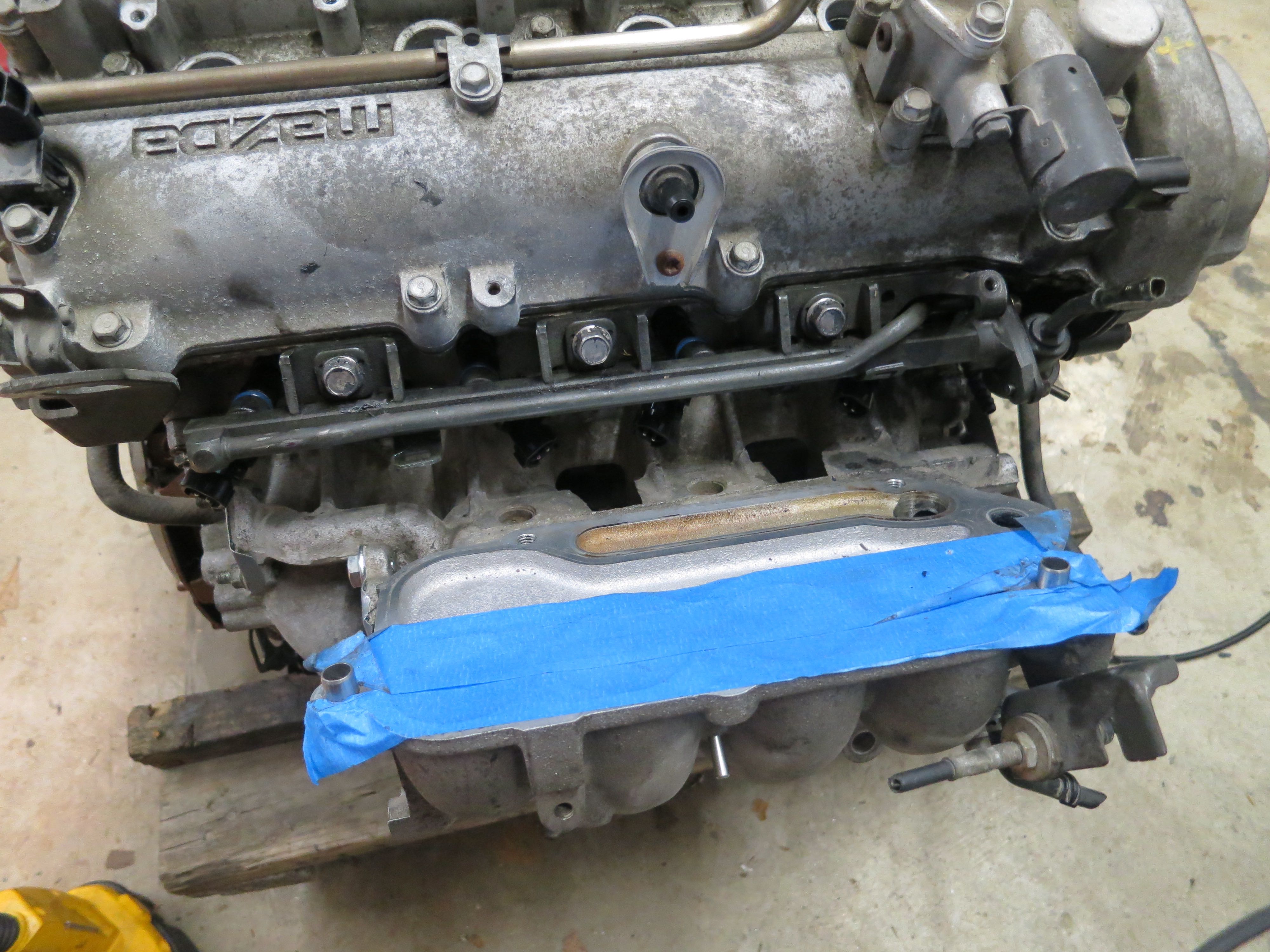
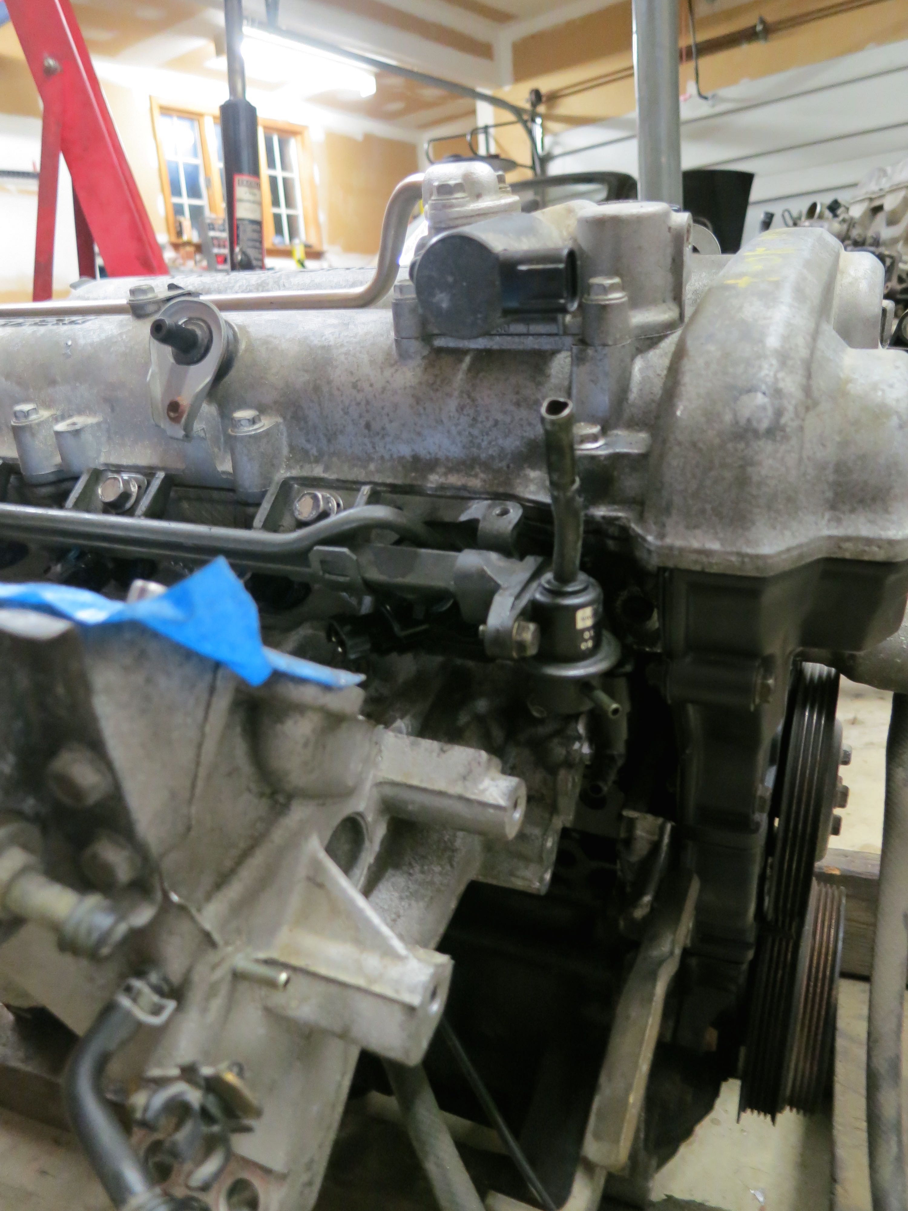
Okay, here are the photos of that rail I got. I took a (bad) picture of it in place without the top part of the manifold, and another one on my desk:


You can see the pipe that goes around the rail is slightly bent to clear the head. Otherwise the rail is as it was, still with the fuel pipes on and all...
You can see the pipe that goes around the rail is slightly bent to clear the head. Otherwise the rail is as it was, still with the fuel pipes on and all...
Reply
0
0

 04-22-2015, 05:37 PM
#140
Junior Member
Join Date: Mar 2012
Location: Portugal
Posts: 200
Total Cats: -12
Apart from the pipe that I had to slightly bend, the manifold clears the fuel rail just fine. Both pipes come out on below the throttle body. This is using the flat top manifold of course, I'm unsure about the VICS or VTCS ones...
Now, the rail looks just like gjsmith66's, except for the connector on the inlet pipe and the fact that it came with an FPR. Does it belong to a 94-97 then?
Now, the rail looks just like gjsmith66's, except for the connector on the inlet pipe and the fact that it came with an FPR. Does it belong to a 94-97 then?
Reply
0
0


