Is this Machinable? (FSAE Senior Project)
 10-28-2013, 11:13 PM
#1
Senior Member
Thread Starter
iTrader: (8)

Join Date: Jan 2012
Location: Azusa, CA
Posts: 1,407
Total Cats: 116
I figured this would be a good place to ask since there quite a few talented and experienced machinist in here.
These components are for an FSAE Carbon Fiber A-arm suspension. They will be made out of aluminum most likely. The tabs will probably be machined in (they aren't modeled that way because these are just a crude concept sketchs). These are for mounting the push/pull rods.
The first CAD model is the ideal method to save weight. The CF tube ID will slip over the insert rods.
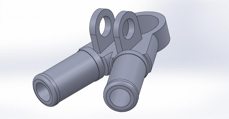
The second CAD model was an attempt to make machining more reasonable. The OD of he CF tubes will insert into the holes of the piece.
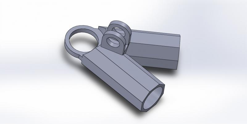
I will shed more weight from these models and refine the designs later but I am more concerned about manufacturability at this point. What do you guys think?
.
These components are for an FSAE Carbon Fiber A-arm suspension. They will be made out of aluminum most likely. The tabs will probably be machined in (they aren't modeled that way because these are just a crude concept sketchs). These are for mounting the push/pull rods.
The first CAD model is the ideal method to save weight. The CF tube ID will slip over the insert rods.
The second CAD model was an attempt to make machining more reasonable. The OD of he CF tubes will insert into the holes of the piece.
I will shed more weight from these models and refine the designs later but I am more concerned about manufacturability at this point. What do you guys think?
.

Reply
 0
0

0
 10-29-2013, 12:59 AM
#5
Senior Member
Thread Starter
iTrader: (8)
Join Date: Jan 2012
Location: Azusa, CA
Posts: 1,407
Total Cats: 116
Thanks for the advice. Once again, just concept sketches... Small issues like that will be addressed when later in the design phase.
Reply
0
0
10-29-2013, 05:07 AM
#9
Elite Member

iTrader: (5)
Join Date: Oct 2011
Location: Detroit (the part with no rules or laws)
Posts: 5,677
Total Cats: 800
Completely possible. Like what he said though, it needs a few small changes.
Other than that, it's going to have to be fixtured like 4 different ways. Plus it's going to be pretty costly.
Other than that, it's going to have to be fixtured like 4 different ways. Plus it's going to be pretty costly.
Reply
0
0

 10-29-2013, 11:18 AM
#13
Elite Member
iTrader: (9)
Join Date: Jun 2006
Location: Chesterfield, NJ
Posts: 6,893
Total Cats: 399
Not being a programmer but dealing with crybaby programmers daily, either look 3axis doable once you make the walls straight, as been mentioned.
Hell, you could also do it on a bridgeport depending on how much you value your time. I'm amazed at what some of the old-timers in the prototype shop can do with manual machines and proper tooling & fixturing.
Hell, you could also do it on a bridgeport depending on how much you value your time. I'm amazed at what some of the old-timers in the prototype shop can do with manual machines and proper tooling & fixturing.
Last edited by TurboTim; 10-29-2013 at 11:41 AM.
Reply
0
0
10-29-2013, 11:19 AM
#14
Elite Member
iTrader: (5)
Join Date: Oct 2011
Location: Detroit (the part with no rules or laws)
Posts: 5,677
Total Cats: 800
The shop i work at makes a ton of little parts like that. 95% of the time it's more than one piece. I'm usually welding it, or someone is, then it goes out for heat treatment and stress relief. Sometimes even goes back into the machine for finish work.
With the proper weld and a good process it should be just as strong as a billet unit.
With the proper weld and a good process it should be just as strong as a billet unit.
Reply
0
0
10-29-2013, 11:35 AM
#15
Cpt. Slow
iTrader: (25)
Join Date: Oct 2005
Location: Oregon City, OR
Posts: 14,192
Total Cats: 1,135
Yeah, anything is possible.
Coming from the manufacturing world, if you want to make a bunch and have them be strong, lathe the steel tubes, stamp or laser cut the tabs, machine the Y shaped boss on a burn table followed by a 3-axis mill (burn-face-flip-face-bore) then weld the three together.
But again, for a one-off piece (or I'm guessing two-off), it's all doable as one piece.
Reply
0
0
10-29-2013, 12:41 PM
#16
Senior Member
Thread Starter
iTrader: (8)
Join Date: Jan 2012
Location: Azusa, CA
Posts: 1,407
Total Cats: 116
The shop i work at makes a ton of little parts like that. 95% of the time it's more than one piece. I'm usually welding it, or someone is, then it goes out for heat treatment and stress relief. Sometimes even goes back into the machine for finish work.
With the proper weld and a good process it should be just as strong as a billet unit.
With the proper weld and a good process it should be just as strong as a billet unit.
Yeah, anything is possible.
Coming from the manufacturing world, if you want to make a bunch and have them be strong, lathe the steel tubes, stamp or laser cut the tabs, machine the Y shaped boss on a burn table followed by a 3-axis mill (burn-face-flip-face-bore) then weld the three together.
But again, for a one-off piece (or I'm guessing two-off), it's all doable as one piece.
Coming from the manufacturing world, if you want to make a bunch and have them be strong, lathe the steel tubes, stamp or laser cut the tabs, machine the Y shaped boss on a burn table followed by a 3-axis mill (burn-face-flip-face-bore) then weld the three together.
But again, for a one-off piece (or I'm guessing two-off), it's all doable as one piece.
The other option I am looking into is making them out of titanium and having them welded.
Not being a programmer but dealing with crybaby programmers daily, either look 3axis doable once you make the walls straight, as been mentioned.
Hell, you could also do it on a bridgeport depending on how much you value your time. I'm amazed at what some of the old-timers in the prototype shop can do with manual machines and proper tooling & fixturing.
Hell, you could also do it on a bridgeport depending on how much you value your time. I'm amazed at what some of the old-timers in the prototype shop can do with manual machines and proper tooling & fixturing.
Ya, it as amazing what some machinist are capable of. Unfortunately I am not one. lol. These would either need to be simplified or we have access to a 3 axis CNC mill at school.
Another option I'm looking into is titanium rapid prototyping if we can find a vendor to sponsor us.
Thanks everyone for the input.
Reply
0
0
10-29-2013, 01:04 PM
#17
Elite Member
iTrader: (5)
Join Date: Oct 2011
Location: Detroit (the part with no rules or laws)
Posts: 5,677
Total Cats: 800
This is all depending on number of parts...
You're going to pay loads less on welding a few pieces together than you would trying to CnC one piece....
Unless you have someone to program and run a CnC for free.
You're going to pay loads less on welding a few pieces together than you would trying to CnC one piece....
Unless you have someone to program and run a CnC for free.
Reply
0
0

Thread
Thread Starter
Forum
Replies
Last Post


