adding a knock sensor to DIYPnP 1.6
 01-09-2012, 10:02 AM
#41
Junior Member

Join Date: Jun 2009
Posts: 126
Total Cats: 4
Yes...............??

I was going to wire the yellow from the DTEC-FC connector on the knocklite via the db15 on the DIYPNP to ADC1 on the main board , am I on the right track? I am a bit unsure of the settings to use in tunerstudio though....
Barry
Last edited by Baz; 01-09-2012 at 10:25 AM.

Reply
 0
0

0
01-16-2012, 01:05 PM
#42
Junior Member
Join Date: Jun 2009
Posts: 126
Total Cats: 4
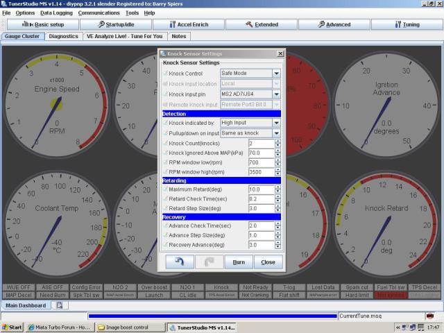
Need a bit of help guys, please be gentle with me!! I have wired up the yellow DTEC-FC wire from my knocklite to AD1 via the db15 on the DITPNP. I have turned on the knock sensor settings and selected safe mode, high input, I have kept the remaining settings as default.
On starting the car, ms pulls 10 degrees all the time, the knock retard gauge is reading 10 and I am idling at 4 degrees instead of 14 (according to the Ingnition advance Gauge).
When I rev the car the knock retard gauge drops to zero and then goes back to 10 degrees, I was expecting to see the retard gauge at zero then react to the knocklite if there was a knock event. I have set the knock lite to 1 (most sensitive) and it does flash at high revs (Noise not knock).
here is a pic of the settings I am using, appreciate any help/advice...
Do I need to do anything in output port settings? I'm a liitle confused here as Matt suggested I wire my Boost circuit to PA0, but in output port settings PA0 is the knock output Help................
Barry
On starting the car, ms pulls 10 degrees all the time, the knock retard gauge is reading 10 and I am idling at 4 degrees instead of 14 (according to the Ingnition advance Gauge).
When I rev the car the knock retard gauge drops to zero and then goes back to 10 degrees, I was expecting to see the retard gauge at zero then react to the knocklite if there was a knock event. I have set the knock lite to 1 (most sensitive) and it does flash at high revs (Noise not knock).
here is a pic of the settings I am using, appreciate any help/advice...
Do I need to do anything in output port settings? I'm a liitle confused here as Matt suggested I wire my Boost circuit to PA0, but in output port settings PA0 is the knock output
Help................Barry
Reply
0
0
01-16-2012, 01:48 PM
#43
Boost Pope


iTrader: (8)
Join Date: Sep 2005
Location: Chicago. (The less-murder part.)
Posts: 33,027
Total Cats: 6,593
This is the opposite of what the MS expects to see. (It makes no sense, I know.)
In order for this to work, the signal will need to be inverted. This can be accomplished with one NPN transistor and a couple of resistors, as such:
This circuit can be built inside the MS, and it simply causes the signal hitting the MS to be opposite the signal coming in from the KnockLite. When the knocklite is at 0v, the transistor is off, and +5 flows through the resistor to the MS's JS10 terminal. When the knocklite goes to +5, it causes the transistor to turn on and drains the pullup voltage to ground, causing 0v to appear at the MS's JS10 terminal.
Reply
0
0
01-16-2012, 02:36 PM
#44
Junior Member
Join Date: Jun 2009
Posts: 126
Total Cats: 4
Thanks Joe, appreciate that, so I could build this in the proto area? you will have to excuse the questions as I have never built a circuit from scratch before!! I think I have the 1k resistors, Is this NPN I need?
http://www.ebay.co.uk/itm/10-x-2N440...item43a663307b
So basically:
output from knocklite to the centre pin of the NPN with a 1k in between.
outer pin to ground.
remaining outer pin to 5v with a 1k in between and a jumper from that pin to js10
Does it matter which way round the outer pins go ?
I take it this totally bypasses AD1, and I dont need to do anything in the output port settings?
Again sorry for the seemingly stupid questions Joe........
Barry
Reply
0
0
 01-16-2012, 05:21 PM
#46
Boost Pope
iTrader: (8)
Join Date: Sep 2005
Location: Chicago. (The less-murder part.)
Posts: 33,027
Total Cats: 6,593
I think I have the 1k resistors, Is this NPN I need?
http://www.ebay.co.uk/itm/10-x-2N440...item43a663307b
http://www.ebay.co.uk/itm/10-x-2N440...item43a663307b
EDIT: Yes, Maplins. Thanks, richyvrlimited
I usually employ the PN2222 or 2N2222 transistor for this sort of task, but having glanced briefly at the datasheet for the 2N4401, it would seem to be adequate. Frankly, this is a very simple circuit, and the exact specifications for the transistor are not critical. You could practically pick a transistor up off the ground at random, and so long as it was NPN, it would probably work in this circuit.
Does it matter which way round the outer pins go ?
In the diagram I posted, the leg on the left is the Base. The upper-right leg is the Collector, and the lower-right leg (with the arrow) is the Emitter. Each of these has a specific function and polarity. In the datasheet for whichever transistor you choose there will be a diagram showing which lead is which function, such as this:
I take it this totally bypasses AD1, and I dont need to do anything in the output port settings?
As I don't have a high degree of familiarity with the DIYPnP, all I can say as to the specific physical pin you need to use is "ask someone else." I know that it needs to hit the microprocessor at either AD6-1 (AN06) or AD7-1 (AN07) from the point of view of the CPU itself, and which I think correspond to pads called "ADC1" or "ADC2" on the DIYPnP board. (I cannot be certain of this, as no schematics have been published for the DIYPnP mainboard, which means that I cannot compare it to the pinout on the schematic for the MicroSquirt Module which it uses as a processor.)
Reply
0
0
01-16-2012, 06:24 PM
#47
Elite Member
iTrader: (1)

Join Date: Jun 2006
Location: Warrington/Birmingham
Posts: 2,642
Total Cats: 42
Joe, rather than Barry build this circuit, could he not just change the setting 'knock indicated by' from going high to going low?
Or have I grasped the wrong stick?
Or have I grasped the wrong stick?
Reply
0
0
01-16-2012, 08:07 PM
#48
Boost Pope
iTrader: (8)
Join Date: Sep 2005
Location: Chicago. (The less-murder part.)
Posts: 33,027
Total Cats: 6,593
(slaps self on forehead smiley)
I keep thinking about this in MS1 terms, where you're stuck with the polarity they give you. Didn't even realize that MS2 allowed you to change this until I looked more closely at the screenshot posted above.
Or have I grasped the wrong stick?
Reply
0
0
01-17-2012, 02:44 AM
#49
Junior Member
Join Date: Jun 2009
Posts: 126
Total Cats: 4
Thanks Joe/Richy. So, I guess I dont need to build the circuit now as I can change the 'knock Indicated by' setting to High (knocklite gives 5v signal when knock occurs). I am pretty sure that whilst testing this I did have it set to high, so maybe I have one or some of the other settings wrong.
Assumption From TurboXS above - The knocklite outputs a 0-5v square wave for knock signal on the yellow wire. On the blue wire, it outputs rpm.
and....
when the knocklite detects knock, the pin that connects to the DTEC-FC outputs 5v. when not detecting knock, it outputs 0V. that should be able to easily integrate into darn near any engine management system.
Input Wiring From diyautotune's diypnp documentation - You can also use external knock signal conditioning devices, which are often more accurate. To use one of these, you can bring its input in through the DB15 to the ADC1 or ADC2 pin. Normally, the signal the DIYPNP is looking for is a 5 volt signal that is pulled to 0 volts when knock occurs, though firmware allows switching this.
ADC1 or 2 are not labled on the mainboard (they are labled AD1 and AD2) so as per Matt Cramers advice, I have the yellow knocklite wire soldered (via the db15) direct to AD1 (located just below the db9 connector)
Knock sensor settings (above)
Knock input Pin There are 2 options in the pulldown menu:
1. ms2 AD7/js4
2. ms2 AD6/js5
Niether relate to ADC1 or AD1 / ADC2 or AD2 (how confusing is this!!) Which option do I choose?
Pull up/down on input The MSExtra manual states Whether an internal pull-resistor should be applied and in what direction. Setting to 'same as' means that if the connection to the knock module breaks then the Megasquirt will automatically assume that knock is happening and pull timing. Set it to this unless you know otherwise.
Options are - Same as knock, none, pull up and pull down. I have this set to 'same as'.
Knock ignored above MAP (kpa) The default setting is 70kpa, surely this cant be right? I assume I would want to monitor knock over most of the MAP?
Output Port Settings As MS is looking for a 'knock Input' of 5v I assume I do not need to touch any of these settings?
This all may not work but I really want to give it a go so any help/advice would be welcome.
Barry
Last edited by Baz; 01-17-2012 at 03:18 AM.
Reply
0
0
01-17-2012, 03:28 AM
#50
Elite Member
iTrader: (1)
Join Date: Jun 2006
Location: Warrington/Birmingham
Posts: 2,642
Total Cats: 42
Yeah you want knock ignore above kpa value to be way WAY higher than that 
The pin labelling thing is a major bugbear of mine, every single pin seems to have 3 names for it and there doesn't seem to be a lookup table anywhere to translate it.
The pin labelling thing is a major bugbear of mine, every single pin seems to have 3 names for it and there doesn't seem to be a lookup table anywhere to translate it.
Reply
0
0
01-17-2012, 04:00 AM
#51
Junior Member
Join Date: Jun 2009
Posts: 126
Total Cats: 4
Found a bit more info on the pin ID's (Thanks Reverant!!):
JS0 = PT6 = IAC1
JS2 = PT7 = IAC2
JS4 = ADC7 = DIYPNP ADC2
JS5 = ADC6 = DIYPNP ADC1
JS7 = PE0
JS11 = PA0
R1 = PE1
FP = PE4
Fidle = PM2
INLED = PM3
ALED = PM4
WLED = PM5
So I am using AD1 (ADC1) input therefore I need to use the ms2 AD6/JS5 setting on the dropdown box I think.
diyautotune should really sort out the pin identification, or at least produce a good look up guide.......
Reply
0
0
01-17-2012, 04:53 AM
#52
Elite Member
iTrader: (1)
Join Date: Jun 2006
Location: Warrington/Birmingham
Posts: 2,642
Total Cats: 42
I don't think it's DIY autotunes place to fix the developers decisions. They may well have made sense to them, but for someone new to the platform they're very confusing.
Reply
0
0
01-17-2012, 05:54 AM
#53
Junior Member
Join Date: Jun 2009
Posts: 126
Total Cats: 4
Ok, been out and done some testing:
Ignition on, set knock input pin to MS2 AD6 JS5 on High input. when I burn, the knock retard gauge stays at zero, when I start the car the gauge reads 10 degrees and pulls 10 degrees of timing at idle and at all revs - Not good!!
I then switched off and disconnected the knocklite yellow wire and it does exactly the same as above.
If I change to knock indicated by 'low input', with the knocklite wire connected the retard gauge stays at 0 when I start the car. If I disconnect the wire the gauge jumps to 10 degrees.
set at low input I went for a drive, with the knocklite set at its most sensitive setting the knocklite lit but there was no indication of timing retard on the datalog.
Help.........please..
Barry
Reply
0
0
01-17-2012, 07:10 AM
#56
Junior Member
Join Date: Jun 2009
Posts: 126
Total Cats: 4
I have just put a meter across the yellow knocklite wire and ground, it is showing 4.85v at idle, this goes against what TurboXS said (when the knocklite detects knock, the pin that connects to the DTEC-FC outputs 5v. when not detecting knock, it outputs 0V).
I assume if I go for a drive and with the meter across the yellow wire, get the knocklite to register knock and see if it goes from 5v to zero? If it does then at least we know how the knocklite works and we can go from there...hopefully....
Barry
I assume if I go for a drive and with the meter across the yellow wire, get the knocklite to register knock and see if it goes from 5v to zero? If it does then at least we know how the knocklite works and we can go from there...hopefully....
Barry
Reply
0
0
01-17-2012, 07:49 AM
#57
Junior Member
Join Date: Jun 2009
Posts: 126
Total Cats: 4
Just been out for a drive to test the knocklite yellow wire output, wife holding meter. With the meter across the yellow and ground I got a steady 5v when driving, with the knocklite on its most sensitive setting I planted my right foot and and the locklite lit up (noise not knock), the 5v remained constant, it did not drop to zero, no fluctuation whatsoever.
When I tested the Blue wire (turboxs state that this is RPM) I got a steady 5v at ignition and the voltage dropped as the revs got higher, so I think this wire is rpm as they state.
I dont want to give up on this but I think I have just wasted 2 days of my life!! I await a reply from TurboXS......
Barry
Reply
0
0
01-17-2012, 08:38 AM
#58
Junior Member
Join Date: Jun 2009
Posts: 126
Total Cats: 4
Found this on the net (not confirmed by turboxs):
'The output signal on the yellow wire pulls down from 5 volts temporarily for a few microseconds (2-10uS) for each time the noise exceeds the threshold'
And
'If you wanted the signal from the Knocklite to pulse for longer, you could put a capacitor between the wire and signal ground (assuming the output from the Knocklite is an open-collector, which pulls to ground in the 'on' state).
To choose the capacitor value, the time constant (in seconds) = 100,000 * capacitance (eg. 10 microfarads = 1 second)'
If this is confirmed, maybe my meter would not pick it up? Could a MS Guru confirm if MS would pick up the drop in signal if it is that quick?
Barry
Reply
0
0
01-17-2012, 11:30 AM
#59
Junior Member
Join Date: Jun 2009
Posts: 126
Total Cats: 4
Just tried something else. With everything connected, the yellow knocklite wire is providing 5v to MS (which is what MS wants), on low input setting and the the engine running, if I momentarily disconnect the yellow wire (for a split second) the Retard gauge goes up to 10, MS retards the timing, then gradually recovers back to zero, so MS is working perfectly. The time between 5v-disconnection-5v determines the degrees that are pulled, if I do it really quick it just pulls 3 degrees then recovers back to zero.
So if the yellow wire does go to zero volts when knock is detected it is doing it too quick for MS to detect. Could someone explain the 'Retard Check Time' in the knock sensor settings? how low could I go with that setting? could it match the time the knocklite is putting out?
If this is not possible I guess the next stage will be for TurboXS to confirm the 2-10uS microsecond voltage pull down time and build a circuit to extend that time (I would not have a clue here!!) so MS could react.
At least it shows that the MS bit works a treat!
Barry
Reply
0
0


