MS Part 2 - The search for more pain! (WTF 5k rev-limit pls help)
 04-09-2009, 05:50 AM
#1
Junior Member
Thread Starter
iTrader: (1)

Join Date: Apr 2008
Location: Bristol
Posts: 439
Total Cats: 0
Some of you may, though most of you probably will not remember my build a while back. MS1 built inside a Mazda case, nice and stealth but plagued by a missfire and bad tach signal.
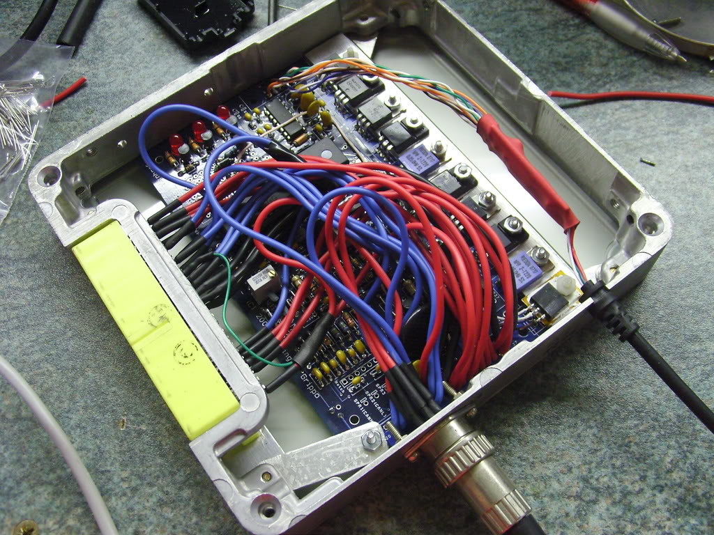
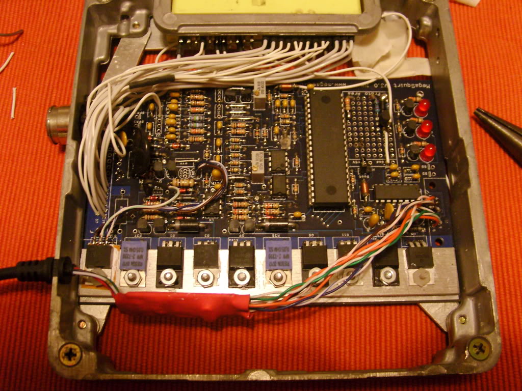
Eventually I gave up and went back to the stock ECU. One rainy weekend I decided to give it another go and build a 36-1 wheel system and whilst I was there I also totally rewired the MS using teflon coated aircraft wire that I swiped from work.
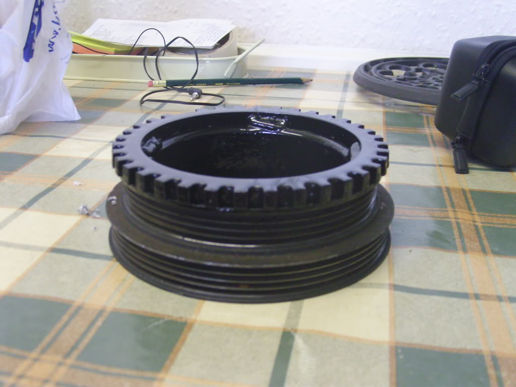
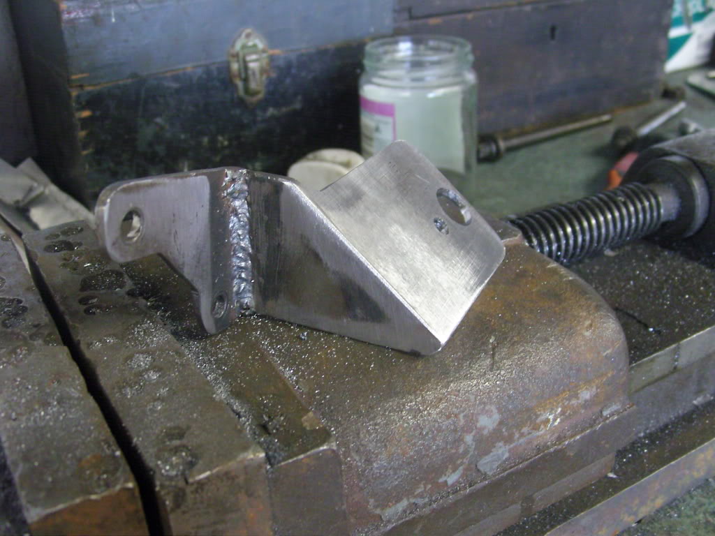
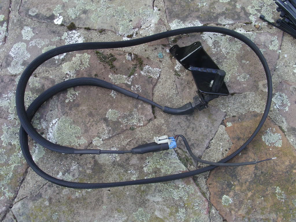
The trigger wheel was cut from 8mm steel plate and then welded to the inner ring of the harmonic balancer that is directly connected to the crank. I then turned it on my lathe to remove any runout . The interesting looking bracket bolts through the first 2 bolts on the left hand side of sump so the sensor is looking at the wheel from about 8 o'clock.
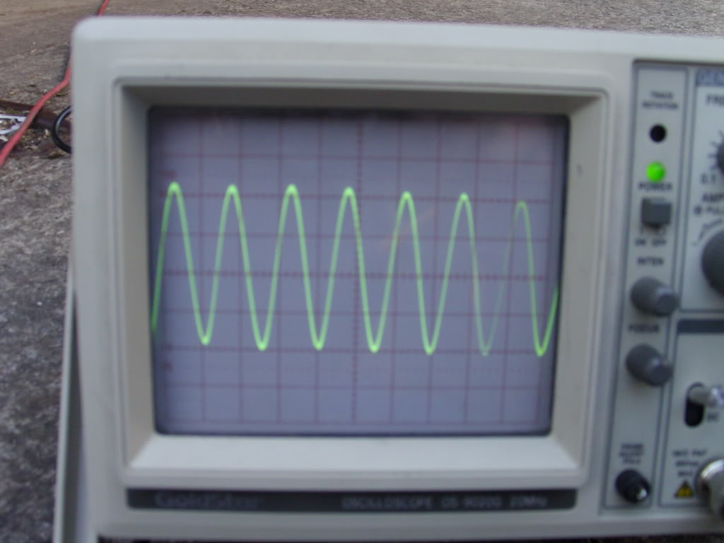
And the result is a nice looking waveform from the sensor yay!! I tried to capture the zero crossing but couldn't get the camera to do it :(
The car now runs smooth as silk with no missfires and I am a very happy man.....Untill I try to rev past 4.5 - 5k boom bang splutter buck clank ****.
I have a nice screen cap of the log showing my various problems.
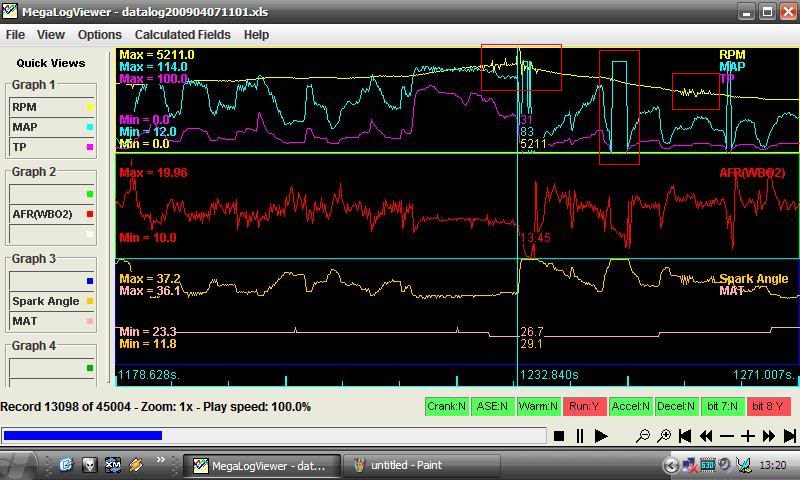
The first little red box shows the RPM as it goes nuts at 5k and jumps around (this also manifests itself on the car tach as the needle jumping around). The second red box shows how sometimes when slowing on 0% throttle my MAP jumps from 0-100kpa!!??. And the third shows a small blip on the tach signal at around 3k but it can pull through this one.
I think that the tach signal is probably the result of wrongly adjusted resistors on the VR conditioner. ATM I'm running the MS base settings of both pots fully counter clockwise. Any suggestions?
The MAP signal baffles the hell out of me.
Any suggestions or advice on the above is greatly appreciated.
Thanks
Eventually I gave up and went back to the stock ECU. One rainy weekend I decided to give it another go and build a 36-1 wheel system and whilst I was there I also totally rewired the MS using teflon coated aircraft wire that I swiped from work.
The trigger wheel was cut from 8mm steel plate and then welded to the inner ring of the harmonic balancer that is directly connected to the crank. I then turned it on my lathe to remove any runout . The interesting looking bracket bolts through the first 2 bolts on the left hand side of sump so the sensor is looking at the wheel from about 8 o'clock.
And the result is a nice looking waveform from the sensor yay!! I tried to capture the zero crossing but couldn't get the camera to do it :(
The car now runs smooth as silk with no missfires and I am a very happy man.....Untill I try to rev past 4.5 - 5k boom bang splutter buck clank ****.
I have a nice screen cap of the log showing my various problems.
The first little red box shows the RPM as it goes nuts at 5k and jumps around (this also manifests itself on the car tach as the needle jumping around). The second red box shows how sometimes when slowing on 0% throttle my MAP jumps from 0-100kpa!!??. And the third shows a small blip on the tach signal at around 3k but it can pull through this one.
I think that the tach signal is probably the result of wrongly adjusted resistors on the VR conditioner. ATM I'm running the MS base settings of both pots fully counter clockwise. Any suggestions?
The MAP signal baffles the hell out of me.
Any suggestions or advice on the above is greatly appreciated.
Thanks
Last edited by Duckie_uk; 04-29-2009 at 05:48 PM.

Reply
 0
0

0
04-09-2009, 06:10 AM
#2
Newb

Join Date: Sep 2008
Location: UK
Posts: 39
Total Cats: 0
When i used to race rc cars i learnt that for signal wires, crossing them is really bad news as it creates a huge amount of interference. I notice that all your db9 wires are all crossed, try uncrossing them as you shouldn't be getting that much noise. Your log shows a LOT of noise! In general you have a lot of wires in close proximity i am no expert but it dosen't look too good.
Reply
0
0
04-09-2009, 06:26 AM
#3
Junior Member
Thread Starter
iTrader: (1)
Join Date: Apr 2008
Location: Bristol
Posts: 439
Total Cats: 0
Serial communications are digital they either work or they dont. They dont suffer from noise superimposing itself on the signal. The only noisy signal I can see on the log is the AFR which is either down to my rough tune or the LC-1 controllers built in GAYNESS about where its grounded.
Reply
0
0
 04-11-2009, 06:10 PM
#5
Junior Member
Thread Starter
iTrader: (1)
Join Date: Apr 2008
Location: Bristol
Posts: 439
Total Cats: 0
Do you mean the LC-1 or the MS? LC-1 has both earths wired directly into the MS board and the MS has the 4 earths on the stock harness wired directly to the board.
Thinking about it now didn't Joe have a problem with not being able to rev just before his car died and needed a toe home? Turned out to be the VR sensor in reverse polarity. Me thinks I'll go over the install with a scope again and maybe try reversing the sensor wires.
Thinking about it now didn't Joe have a problem with not being able to rev just before his car died and needed a toe home? Turned out to be the VR sensor in reverse polarity. Me thinks I'll go over the install with a scope again and maybe try reversing the sensor wires.
Reply
0
0
04-11-2009, 07:21 PM
#6
Boost Pope


iTrader: (8)
Join Date: Sep 2005
Location: Chicago. (The less-murder part.)
Posts: 33,052
Total Cats: 6,615
If you can grab a capture of a missing tooth on the scope, that would help diagnose the problem. Ideally, the raw signal into the MS on channel A, and the output of the VR decoder into the CPU on channel B.
Reply
0
0
04-14-2009, 04:34 AM
#7
Junior Member
Thread Starter
iTrader: (1)
Join Date: Apr 2008
Location: Bristol
Posts: 439
Total Cats: 0
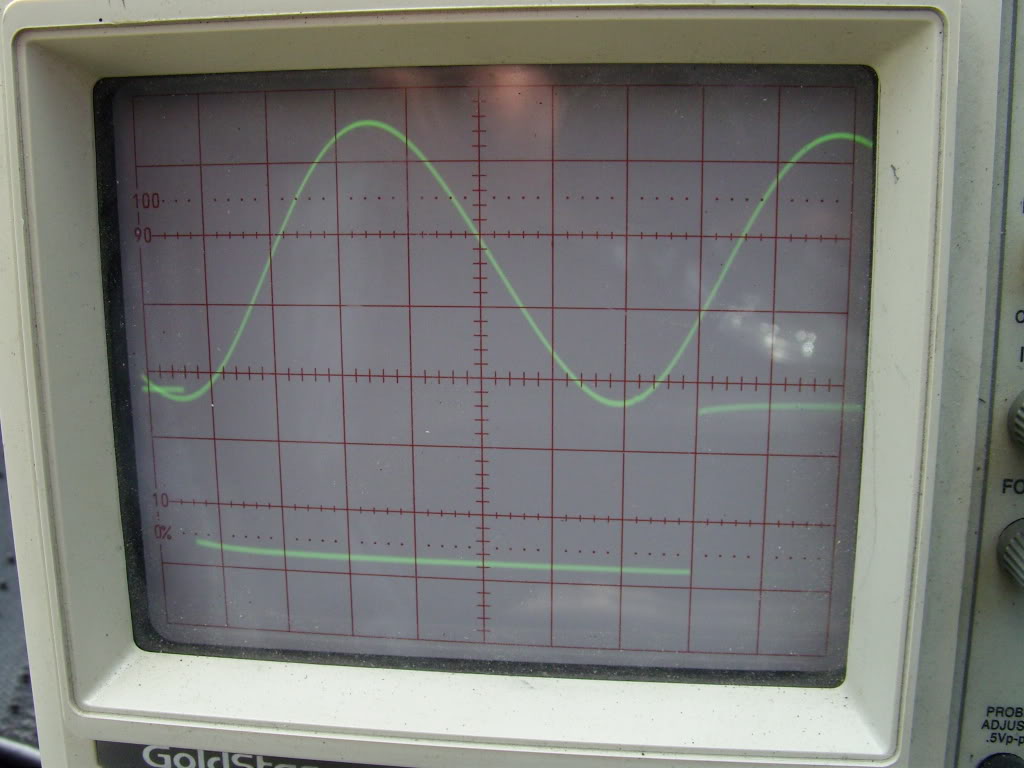
And we have scope caps. Unfortunately my scope is a little older than I am so unfortunately I cannot get the two traces to synchronise.
First pic shows normal operation.
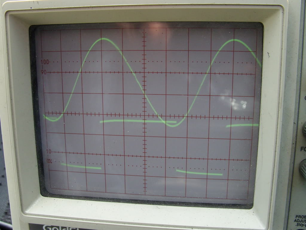
Second pic shows missing tooth
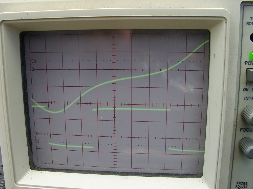
Third pic shows the resulting output.
I started by running a separate set of wires directly from the MS to the VR sensor just in case I was getting interference by using the mazda harness. But no change.
By messing around with the trigger and hysteresis pots I managed to get about 500rpm more out of the engine. That makes me think that the problem is with my wheel/sensor setup rather than with my MS.
I have pulled the MS now and gone back to stock so I can mess with the MS on the bench. I'm going to give it a shot on the crankpulser program and see if I can get it to work nicely.
First pic shows normal operation.
Second pic shows missing tooth
Third pic shows the resulting output.
I started by running a separate set of wires directly from the MS to the VR sensor just in case I was getting interference by using the mazda harness. But no change.
By messing around with the trigger and hysteresis pots I managed to get about 500rpm more out of the engine. That makes me think that the problem is with my wheel/sensor setup rather than with my MS.
I have pulled the MS now and gone back to stock so I can mess with the MS on the bench. I'm going to give it a shot on the crankpulser program and see if I can get it to work nicely.
Reply
0
0
04-14-2009, 12:15 PM
#8
Junior Member

Join Date: Dec 2008
Location: CA
Posts: 81
Total Cats: 1
I put EDIS on a Fiat x1/9 a few months ago, the spec for the sensor spacing from the wheel is .5mm if you didn't know. I had issues with R12, stock 370K ohm doesn't like EDIS (EDIS spec is 1K), although you are using VR directly, try that.
Reply
0
0
04-27-2009, 05:55 AM
#9
Junior Member
Thread Starter
iTrader: (1)
Join Date: Apr 2008
Location: Bristol
Posts: 439
Total Cats: 0
This weekend I put the MS on the bench and gave it a shot with the crank wheel simulator program. And it fell flat on its ***. So I guess the sensor and wheel are in the clear.
I couldn't get anything using a direct output from a laptop headphone socket. I used some el-cheepo desktop speakers and managed to get rpm readings up to 1300 by cranking the trigger pot way way up. Aha I think, DC offset, and sure enough I found 2-3 VDC from the speakers but I also found just over 1 volt DC coming from the MS itself!! Is this normal? I switched to my valve headphone amp (which better not have any DC on it!!) and now by fiddling with the pots I can just about get to 6000 rpm, but its still jumping around higher in the rev range.
Why the hell would my VR circuit be so super sensitive to trigger voltage and hysterysis when I'm using a (theoretically) perfect trigger signal amplified way the hell up to over 13V peak-peak? And I really do mean super sensitive, 1 turn either way on the trigger voltage pot means that I can only get rpm up to 3k or so.
I am considering trying out the LM18xx VR decoder circuit as used on the VR board from jbperf but I have had mixed reviews. Has anyone tried it on both modes (adaptive and zero crossing) results?
Reply
0
0
04-29-2009, 05:40 PM
#10
Junior Member
Thread Starter
iTrader: (1)
Join Date: Apr 2008
Location: Bristol
Posts: 439
Total Cats: 0
Ok its time to shed some win on the situation.
Whilst trawling the MS extra forums I came across a thread posted by someone with similar symptoms to mine. Turns out that there is a discrepancy between the assembly manual and the BOM for the V3 board on the megamanual. One stipulates a value of 0.1uf (104) for C31 the other 0.001 uf (102). Because of this some of the Glens Garage kits shipped with the wrong value (mine was one of those kits). Apparently the larger value stops the trough following the missing tooth from dropping as low as the subsequent troughs causing death and destruction at higher rpms.
With the new value of cap my MS now has no trouble decoding a 8500 rpm signal on the crankpulser, and I can turn both pots back fully CCW.
I'll let you know how it works out on the car when I re-fit it this weekend along with the new waterpump that I should have fitted when I did the timing belt.
Reply
0
0
04-29-2009, 08:33 PM
#11
Boost Pope
iTrader: (8)
Join Date: Sep 2005
Location: Chicago. (The less-murder part.)
Posts: 33,052
Total Cats: 6,615
I built my VR decoder circuit on an external board, but I basically just copied the 3.0 schematic. According to it, C31 is 0.22uf, and I'm guessing that's probably the value that I used. (The 3.57 schematic is the same.)
I did not notice a significant discrepancy in the level of the first tooth after the missing tooth, relative to its neighbors. Here's a scope cap of my crankwheel, with VR on top and decode on bottom:

Despite this, I do very occasionally experience a single-cycle misfire event. By occasionally, we're talking maybe once every couple of months. Still, I wonder if my decoder might be experiencing this phenomenon at higher frequencies (higher RPMs) which is not visible to me at idle?
Reply
0
0
04-30-2009, 02:16 AM
#12
Junior Member
Thread Starter
iTrader: (1)
Join Date: Apr 2008
Location: Bristol
Posts: 439
Total Cats: 0
MSx/Extra EFI • View topic - 36-1 losing sync > 2500rpm with MS2e - VR signal issue fixed
Where were you scoping your signal? I was scoping mine directly from the output of the VR sensor and like yours, all looked fine. I expect if we tried probing further into the VR circuit it would tell a different storey.
EDIT: Just found this in the mega manual.
# Install and solder C31 {399-4329-ND, 0.1�F, 104 marking OR 399-2017-ND, 0.001�F}. This is located as the 4th cap in the row of "vertical" capacitors above "Bowling" in the copyright notice. A 399-2017-ND 0.001 �F capacitor may be substituted for higher frequency inputs; it is especially useful for high tooth count wheels.
# Install and solder C32 {399-2075-ND or 399-4326-ND, 0.01�F, 103 marking}. This is below C31, further from the heat sink. (Note that in some cases, if you experience tach related issues, you can try moving this capacitor.)
# Install and solder D24 {1N4001DICT-ND/1N4148DICT-ND}. Note that this items was originally a 1N4001. However, testing showed that the 1N4148 switching diode has a much faster reverse recovery time which can help with high speed, high voltage signals such as you might get with a missing tooth wheel. Be sure to match the band on the diode to the band on the silkscreen. This is located immediately above the "2005" in the copyright notice, beside R56.
Reply
0
0

Thread
Thread Starter
Forum
Replies
Last Post
mx594m
Local Meets, Events and Tech Days
14
06-08-2012 10:26 PM
castillejos2000
Miata parts for sale/trade
22
09-16-2007 06:53 AM


