MS2 no start, no spark, no rpm signal
 03-28-2014, 10:53 PM
#1
Junior Member
Thread Starter
iTrader: (2)

Join Date: Mar 2013
Location: Livermore, CA
Posts: 138
Total Cats: -18
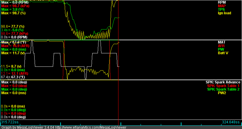
Alright, so I started my car the other day with the stock ecu plugged in and it started and idled fine, I plug in the MS2 for the first time and it doesn't start, I'm not getting any spark or RPM signal at all. Here's a datalog of the crank:
I've got my wiring wired up according to these diagrams:
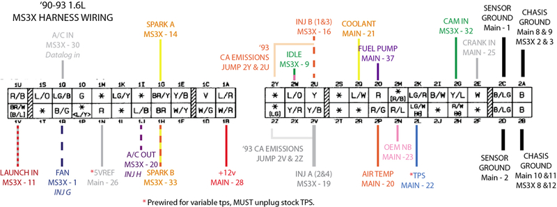

for the grounds, I have pins 15 and 16 of the DB37 going to pin 2A of the harness, pins 17, 18, and 19 going to 2B, and pin 7 going to 2C.
I was unsure how to hook up the VR sensor, right now I have pin 24 of the DB37 hooked up to 2E, and pin 1 hooked up to ground at 2C, though I also tried having pin 1 not be connected to anything and I still have the same result. I really think my issue is in these two wires but I'm not sure exactly how they are supposed to be hooked up. Please help!
If you need any additional info let me know.
I've got my wiring wired up according to these diagrams:
for the grounds, I have pins 15 and 16 of the DB37 going to pin 2A of the harness, pins 17, 18, and 19 going to 2B, and pin 7 going to 2C.
I was unsure how to hook up the VR sensor, right now I have pin 24 of the DB37 hooked up to 2E, and pin 1 hooked up to ground at 2C, though I also tried having pin 1 not be connected to anything and I still have the same result. I really think my issue is in these two wires but I'm not sure exactly how they are supposed to be hooked up. Please help!
If you need any additional info let me know.

Reply
 0
0

0
03-29-2014, 09:39 AM
#2
Senior Member

Join Date: Apr 2011
Location: Hollywood, FL
Posts: 807
Total Cats: 163
You need to have the cam signal too. Follow this if you haven't done so already. From:
http://www.diyautotune.com/tech_arti...azda_miata.htm
MS2 - Getting the Tach Input Signal:
MS2/Extra has a dedicated wheel decoder mode for the Miata. The software calls this 4G63 mode as this is also used on the Mitsubishi 4G63. There are several ways to make this work - note that our way isn't the same as the MS2/Extra manual. However, there are several ways to make this work, and if you follow all the steps in one single write-up, you'll be good to go. The potential trouble spot can happen if you mix and match write-ups.
This article uses a different pinout for the MS2 than the MS1. MS2s normally have the IAC1A through IAC2B jumpers populated by a stepper IAC valve. In this write-up, we'll leave those where they are; you can use them for relays or other I/O. Here's the pinout we will be using.
Board version V3.0 V3.57
CKP signal DB37 pin 24 DB37 pin 24
CMP signal DB37 pin 5 DB15 pin 7
Spark A DB37 pin 36 DB37 pin 36
Spark B DB37 pin 6 DB15 pin 10
Option 1: Spark Output to factory Miata ignitors: (Recommended)
The mods in this article require the spark output to be set to going low. There are some other output mods floating around out there that use the opposite setting.
V3.0 mods:
Parts Needed for PCBv3 Output Mod using factory ignitors: (2) 270 to 330 ohm 1/4w Resistors
Next use two 270 to 330 ohm resistors as pictured below, along with two bits of wire to bring the signals out to the DB37. This will condition the board to use the stock ignitors and coil packs. Take each resistor and cut off all but about � of an inch lead on each side, hook both ends and loop them around the pins that were already soldered. The picture below shows where they go (Note: In this picture they are marked as 1K resistors). The resistor goes from the 5v side of each resistor to the negative leg of the respective LED. This is then brought over to the db37 with two lengths of wire (one for each). The top resistor goes to IGN and the bottom resistor goes to SPR4.
When wiring up your ECU later: Spark Output A will come out on pin 36, and Spark Output B will come out on pin 5.
V3.57 mods:
This board already has a 1K pull up on the spark outputs. If you need a higher pull up value (such as for running our IGN-1A coils), you can run 330 ohm resistors from a 5V source to PAD1 and PAD3.
For spark output A, wire PAD1 to the center hole of Q16.
For spark output B, wire PAD3 to PAD15.
When wiring up your ECU later: Spark Output A will come out on pin 36 of the DB37, and Spark Output B will come out on pin 10 of the DB15.
Reply
0
0
03-29-2014, 11:26 AM
#3
Junior Member
Thread Starter
iTrader: (2)
Join Date: Mar 2013
Location: Livermore, CA
Posts: 138
Total Cats: -18
That's actually the write up I followed, I have done all the above mods for the 3.57 board including the 330 ohm resistors for the spark outputs, and have spark output B and the CMP signal coming out on the db15 connector.
I went back and triple checked all my solder joints on the board and there was one that had a very tiny solder trail that may have been causing a short, I cleaned that up but nothing changed.
According to that write-up, the CKP signal comes out on pin 24, but the diagram shows pin 1 also going to the CKP, I figured this might be ground, but I checked the wiring diagrams and it looks like the CAS has it's own dedicated ground and doesn't come back to the ECU. So I'm not sure were pin 1 should be hooked up.
Reply
0
0
03-29-2014, 12:29 PM
#5
Junior Member
Thread Starter
iTrader: (2)
Join Date: Mar 2013
Location: Livermore, CA
Posts: 138
Total Cats: -18
Did you select 4g63 as your ignition? Yep
When loading firmware did you select the correct ecu? I'm about 99.9% sure that I did. I was having some trouble with this initially because my laptop was having issues with it's video card, but I did successfully load the firmware. I just bought a new laptop though so that's not an issue anymore.
Do you have VTPS or the stock TPS? I'm 1.8 swapped, so I'm using the 1.8 vtps. I wired it up according to a write-up I found, I'm sure I've got it wired it up correctly, I double checked it all using the factory wiring diagrams. With stock ECU it'll idle with the tps plugged in but stumble when you rev it, with it unplugged it revs fine with stock ecu. I also calibrated the TPS in tuner studio and was able to get it to say right around 0% when closed, and 100% when opened (within a percent or two)
Reply
0
0
04-01-2014, 02:47 PM
#7
Junior Member
Thread Starter
iTrader: (2)
Join Date: Mar 2013
Location: Livermore, CA
Posts: 138
Total Cats: -18
Still fighting with this thing. I have checked for voltage on the CKP and CMP wires (I have no option in megatune to see a log of these sensors, is that something you can only do with the paid version?) and have voltage, I checked to see if I needed to add the 12v signal for the CAS but after looking at the wiring diagrams I see it just taps into the 12v wire going to 1B. Now my question is for the ground. The CAS has it's own dedicated ground somewhere but I'm thinking I should run a wire all the way from the twisted black wire from pin 1 to the CAS itself, I did a LOT of searching and could not find this mentioned anywhere of anyone having to do this, but I've checked and rechecked all my connections and this is about all I can think of.
Reply
0
0
04-01-2014, 02:58 PM
#8

You can back probe (stick a needle into the backside of the connector while its plugged into the cas and connect your multimeter to the needle) and then turn the engine by hand. You should see a digital output.
I'm 99% sure that with the ignition on, all of the sensors are active. You probably will want to unplug your ignition coils just to be on the safe side
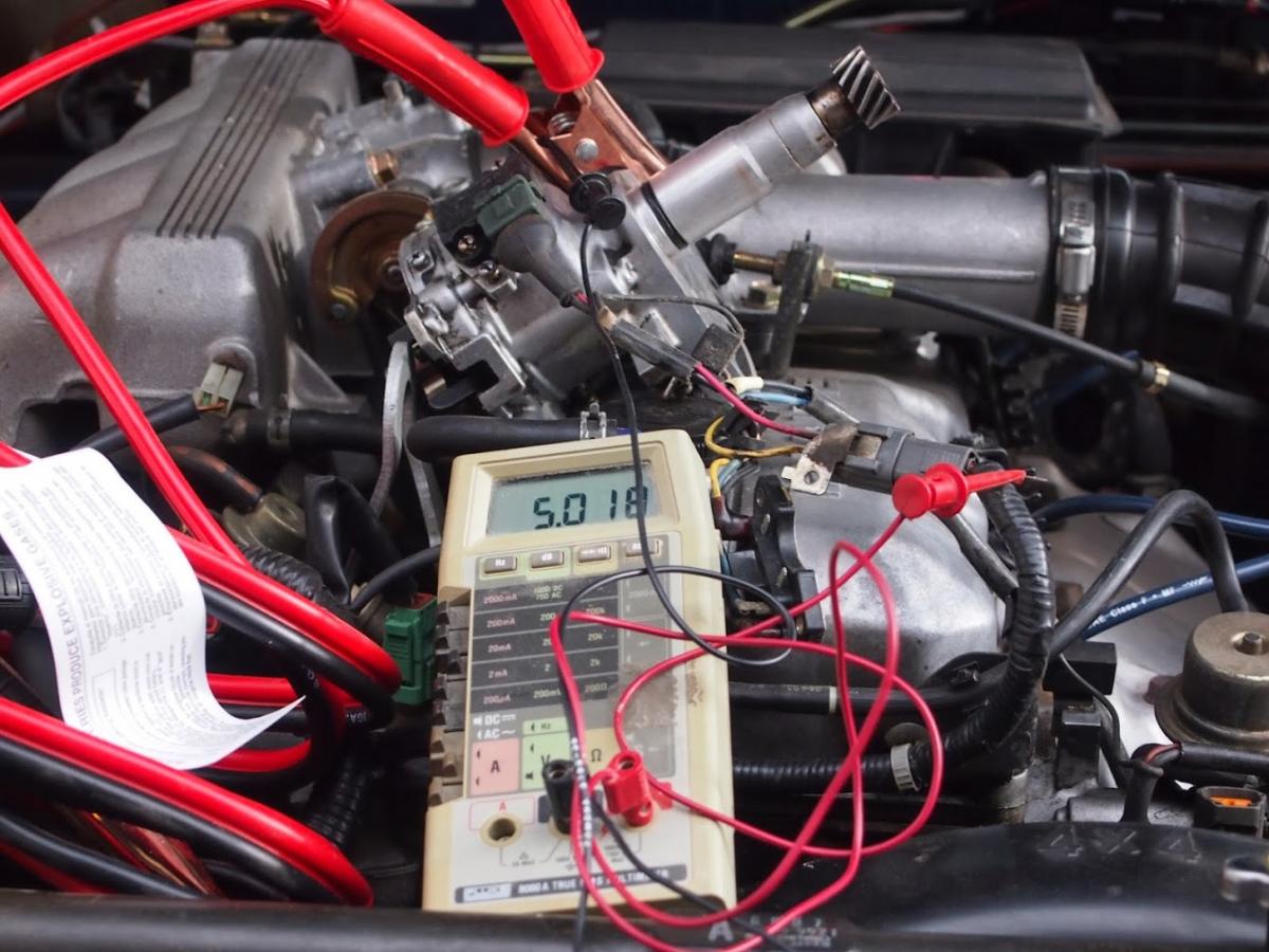
Edit: I know mazda was a fan of grounding sensor components through the direct head connection... Notice in my pic below that I'm using a jumper cable to hook that b2600 dizzy to ground...
The pic shows a hall sensor grounding through the head; it wouldn't surprise me if they did the same with the active optical sensor on the miata. Not sure though...
Here's a pic of me doing this to check out the hall sensor on a dizzy:
I'm 99% sure that with the ignition on, all of the sensors are active. You probably will want to unplug your ignition coils just to be on the safe side
Edit: I know mazda was a fan of grounding sensor components through the direct head connection... Notice in my pic below that I'm using a jumper cable to hook that b2600 dizzy to ground...
The pic shows a hall sensor grounding through the head; it wouldn't surprise me if they did the same with the active optical sensor on the miata. Not sure though...
Here's a pic of me doing this to check out the hall sensor on a dizzy:
Reply
0
0
04-01-2014, 05:15 PM
#9
Junior Member
Thread Starter
iTrader: (2)
Join Date: Mar 2013
Location: Livermore, CA
Posts: 138
Total Cats: -18
ok, just back-probed the CAS with interesting results. with the negative probe of the voltmeter on the ground wire of the CAS and the positive probe on the alternator positive I get 12v, so it has ground to the CAS. With the positive probe on the CMP signal, and with the negative probe on the CAS ground, I get either 0v or 3.74V as i spin the engine, so we have good CMP signal; I also put the negative probe to a known good ground and had the same voltage. Now, when I put the positive probe to the CKP signal, and the negative probe on either the CAS ground or a known good ground (same results with each) I get either 0.00V or 0.03V as the engine spins. So it is getting a signal but it is very weak, I would imagine it should be up closer to 5V like the CMP signal, but I'm not positive on that. So, is my CAS sensor bad? The funny thing is though, the car still starts and runs on the stock ecu just fine, wouldn't it need the CKP signal to run?
Reply
0
0
04-01-2014, 05:32 PM
#10
Was the connector still plugged in?
I'm pretty sure there's a pull-up within the ecu, so to see anything it needs to be plugged in.
A lot of the time the backprobe doesn't make a great connection. Verify connectivity between the needle and the pin to be sure.
Retry the test with the stock ecu and see how it looks.
Edit: Just glanced at the diyautotune page it looks like you need a pullup on the ckp signal:
"CKP Signal" -- We just need a 12v pullup. Install a 470ohm 1/4w resistor between the right side (non-band) end of D5 and the right hole (banded) end of D9."
If it works with the stock ecu, I'd say something is off with the pullup in your MS
Last edited by leboeuf; 04-01-2014 at 05:45 PM.
Reply
1
1
04-01-2014, 06:21 PM
#11
Junior Member
Thread Starter
iTrader: (2)
Join Date: Mar 2013
Location: Livermore, CA
Posts: 138
Total Cats: -18
Ah, I tested it without either ECU plugged in, probing the back of the CAS plug while it was plugged in, using some needles that come with a snap on scan tool that were specifically meant for back probing wires... Here's the results with the stock ECU:
CMP either 0.19V or 5.00V as engine rotated
CKP either 0.19V or 5.00V as engine rotated
Then I tried again with the MS plugged in
CMP 0.33V or 3.35V
CKP 0.19V or 4.89V
So.... is there something wrong with my pullup for CMP?
edit: I followed the instructions for the MS2 3.57 board which is what I'm using.
Originally Posted by diyautotune
"CKP Signal" -- We just need a 5v pullup. Solder a 1K resistor in the R57 slot, above JP1.
"CMP Signal" -- Lay a 1k 1/4watt resistor across the bottom of the PCB with one end at JS10 and the other end at the PAD7 hole. Bend the resistor leads to raise the resistor just a bit off of the PCB and allow a lead on one end to drop through PAD7 and solder that end in place (while making sure the other end is in place near JS10 still, and with the resistor still raised a bit off the board so the leads don't short against anything). Bend the other end to JS10 and solder it in place. Now to get the 5v pullup use a 470 ohm 1/4w resistor and solder one end of it to the leg of the first resistor to PAD7 and the other leg of it to the 5v+ hole just above the LED area. Once again raise this just enough off of the PCB to prevent it from shorting with any of the leads sticking out on the board. (Heatshrink tubing over the whole wire/resistor assembly works nicely)
"CMP Signal" -- Lay a 1k 1/4watt resistor across the bottom of the PCB with one end at JS10 and the other end at the PAD7 hole. Bend the resistor leads to raise the resistor just a bit off of the PCB and allow a lead on one end to drop through PAD7 and solder that end in place (while making sure the other end is in place near JS10 still, and with the resistor still raised a bit off the board so the leads don't short against anything). Bend the other end to JS10 and solder it in place. Now to get the 5v pullup use a 470 ohm 1/4w resistor and solder one end of it to the leg of the first resistor to PAD7 and the other leg of it to the 5v+ hole just above the LED area. Once again raise this just enough off of the PCB to prevent it from shorting with any of the leads sticking out on the board. (Heatshrink tubing over the whole wire/resistor assembly works nicely)
Reply
0
0
04-01-2014, 06:30 PM
#12
I would trace the wires and see why CMP is not reaching 5v. Make sure the signal is strong.
Edit: just noticed your edit
Also if that diyautotune article is correct:
"CKP Signal" -- We just need a 12v pullup. Install a 470ohm 1/4w resistor between the right side (non-band) end of D5 and the right hole (banded) end of D9."
CKP needs a 12v pullup
Double check where you wired the pullup to.
Edit: just noticed your edit
Also if that diyautotune article is correct:
"CKP Signal" -- We just need a 12v pullup. Install a 470ohm 1/4w resistor between the right side (non-band) end of D5 and the right hole (banded) end of D9."
CKP needs a 12v pullup
Double check where you wired the pullup to.
Last edited by leboeuf; 04-01-2014 at 06:44 PM.
Reply
0
0
04-01-2014, 06:50 PM
#13
Junior Member
Thread Starter
iTrader: (2)
Join Date: Mar 2013
Location: Livermore, CA
Posts: 138
Total Cats: -18
I would trace the wires and see why CMP is not reaching 5v. Make sure the signal is strong.
Also if that diyautotune article is correct:
"CKP Signal" -- We just need a 12v pullup. Install a 470ohm 1/4w resistor between the right side (non-band) end of D5 and the right hole (banded) end of D9."
CKP needs a 12v pullup
Double check where you wired the pullup to.
Also if that diyautotune article is correct:
"CKP Signal" -- We just need a 12v pullup. Install a 470ohm 1/4w resistor between the right side (non-band) end of D5 and the right hole (banded) end of D9."
CKP needs a 12v pullup
Double check where you wired the pullup to.
I was going to take a couple pictures of my pullups to show that they were wired correctly when I realized what my whole problem likely is... Instead of the capacitor and 470 ohm resistor being wired to JS10, they are wired to JS11
 I feel stupid...
Reply
0
0
04-01-2014, 10:19 PM
#14
Junior Member
Thread Starter
iTrader: (2)
Join Date: Mar 2013
Location: Livermore, CA
Posts: 138
Total Cats: -18
Ok, I got the pullup and the capacitor which were hooked up to JS11 now hooked up to JS10. I opened up tuner studio and my rpm was reading ~65,000 rpm! There was also a error message saying there was a conflict in the settings. I brought up the little message box and it said the error was between my spark output and spare output settings. I looked in the spare outputs and D16 was enabled for some reason... disabled that, and power cycled the key. No more error message and RPM was reading 0. I cranked it over but I'm still not getting an rpm signal. I measured the voltage at the CAS again and got pretty much the same voltage for the CMP as before so now I'm back to being stumped again...
Reply
0
0
04-01-2014, 11:38 PM
#15
Keep working your way back. How do the signals look right at the db37 (or db15 for 3.57) inside the case. Or better yet right at the microcontroller.
There is still something amiss with your ~3v cmp pull-up. Since the stock ecu correctly provides a full swing we know the cas is likely fine (the sensor simply provides a ground path and it's doing that).
There's something pulling down your signal.
Is the js10 io setup correctly in the software? It seems like it's set to be an output (with an active pulldown) instead of an input...
Reply
0
0
04-02-2014, 03:17 PM
#16
Junior Member
Thread Starter
iTrader: (2)
Join Date: Mar 2013
Location: Livermore, CA
Posts: 138
Total Cats: -18
ok, i've been doing a little probing with an ohmmeter on the board itself. And I noticed that I was only getting 634 ohms between JS10 and Pad 7, despite having a 1K ohm resistor there. I measured from the 5V hole to Pad 7 and had about 385 ohms, despite it having a 470 ohm resistor. The 470 ohm resistor from the 5V hole is soldered to the leg of the 1K resistor before it passes it passes through the Pad 7 hole. I drew up a diagram on MS paint to show what I mean:
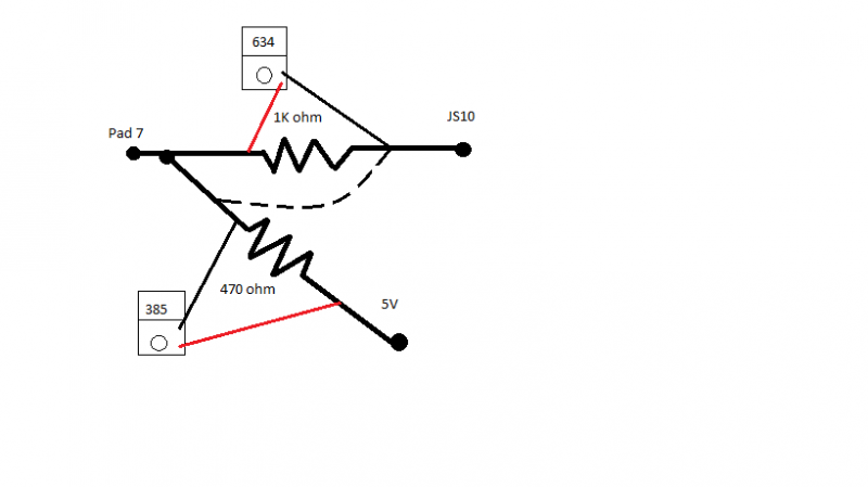
So, I thought maybe I had overheated the resistors when soldering them or something so I de-soldered the 470 ohm from the 1K ohm, after that I measured across them again and the 1K ohm read 980 and the 470 read 462. So, I would imagine that this is normal and what is supposed to happen, or am I really supposed to have 1K ohms between JS10 and Pad 7? The only other way I could see to hook it up would be if I wired the 470 to the other side of the 1k like the dashed line shows in the diagram. I read through the instructions again and it sounds like I have it hooked up right but I could be wrong.
So, I thought maybe I had overheated the resistors when soldering them or something so I de-soldered the 470 ohm from the 1K ohm, after that I measured across them again and the 1K ohm read 980 and the 470 read 462. So, I would imagine that this is normal and what is supposed to happen, or am I really supposed to have 1K ohms between JS10 and Pad 7? The only other way I could see to hook it up would be if I wired the 470 to the other side of the 1k like the dashed line shows in the diagram. I read through the instructions again and it sounds like I have it hooked up right but I could be wrong.
Originally Posted by diyautotune
"CMP Signal" -- Lay a 1k 1/4watt resistor across the bottom of the PCB with one end at JS10 and the other end at the PAD7 hole... Now to get the 5v pullup use a 470 ohm 1/4w resistor and solder one end of it to the leg of the first resistor to PAD7 and the other leg of it to the 5v+ hole just above the LED area.
Reply
0
0
04-02-2014, 03:31 PM
#17
Junior Member
Thread Starter
iTrader: (2)
Join Date: Mar 2013
Location: Livermore, CA
Posts: 138
Total Cats: -18

Here's a view of my settings, it looks like you're right and JS10 is set up to be an output rather than an input. Where should I be getting the Tacho output then, and where do I tell tuner studio to use JS10 as the cam input? I went through all the settings I could and did not see anywhere to tell it where the cam input is.
Reply
0
0
 04-02-2014, 05:28 PM
#19
Junior Member
Thread Starter
iTrader: (2)
Join Date: Mar 2013
Location: Livermore, CA
Posts: 138
Total Cats: -18
I'm sorry, what's the culprit? The fact that it's not getting the full 1k ohms between Pad 7 and JS10? If so, how should I correct that? By connecting it like the dashed line? Or do I need larger resistors?
Reply
0
0
04-02-2014, 06:01 PM
#20
Ahh, I'll provide a little info on I/O.
To preface I'm not all that familiar with the microcontroller that the ms2 is based on.
Say we make a basic I/O that has 2 states of operation, input and output.
When in input mode the output driver circuits are put in high Z state. Basically they are cut off. The input signal then hits the input circuitry which puts a very small load on the signal in order to read it. There's a lot of info out there on input circuitry that I won't go into.
When in output mode, there are massive transistors that get actively connected to the port. Most microcontrollers default to have the output port actively pulled low, so if you connect it to a high impedance input or don't connect it to anything it at all, it doesn't float around. The pulldown will pull it down to ground. There are also active pullups but judging on your measurements the ms2 uses a pulldown.
This is what is likely happening to your circuit. Js10 in output mode is actively pulling your cmp signal low. Your ms will never get your crank signal.
It sounds like your hardware is probably ok, that write up wasn't complicated.
However as long as js10 is setup as an output your ms will never work.
Reply
0
0


