OBD-II data module for all MS2/MS3 ECUs
 09-22-2015, 11:17 AM
#81
Senior Member

Join Date: May 2011
Posts: 638
Total Cats: 76
So is this the part where I get trolled by being taunted with instructions and then receiving none? It would help if you'd answer an email occasionally tbh.

 1
1
 09-22-2015, 12:58 PM
#83
Senior Member
Join Date: May 2011
Posts: 638
Total Cats: 76

There are others... those are just the two from this last week. I have trouble getting email responses... who knows, maybe it's me. What email is best to reach you at? FWIW I'm using the same one I've always used.
Your email still ****@**labs.gr?

Last edited by Reverant; 09-22-2015 at 01:28 PM.
0
09-22-2015, 11:48 PM
#85
Senior Member
Join Date: May 2011
Posts: 638
Total Cats: 76
baby steps. I got the firmware added in for the obd2 module into tunerstudio. It seems that i can connect to it. I am having some issues getting it setup to output obd2 data. I have two different bt adapters. I can connect to the adapters via torque but can't connect or get data from the ecu.
If anyone has a link to where i can read about this it would be appreciated. I am not looking to set it up for can ego over the can bus... once I get the regular settings down I'll get crazy and dig into that.
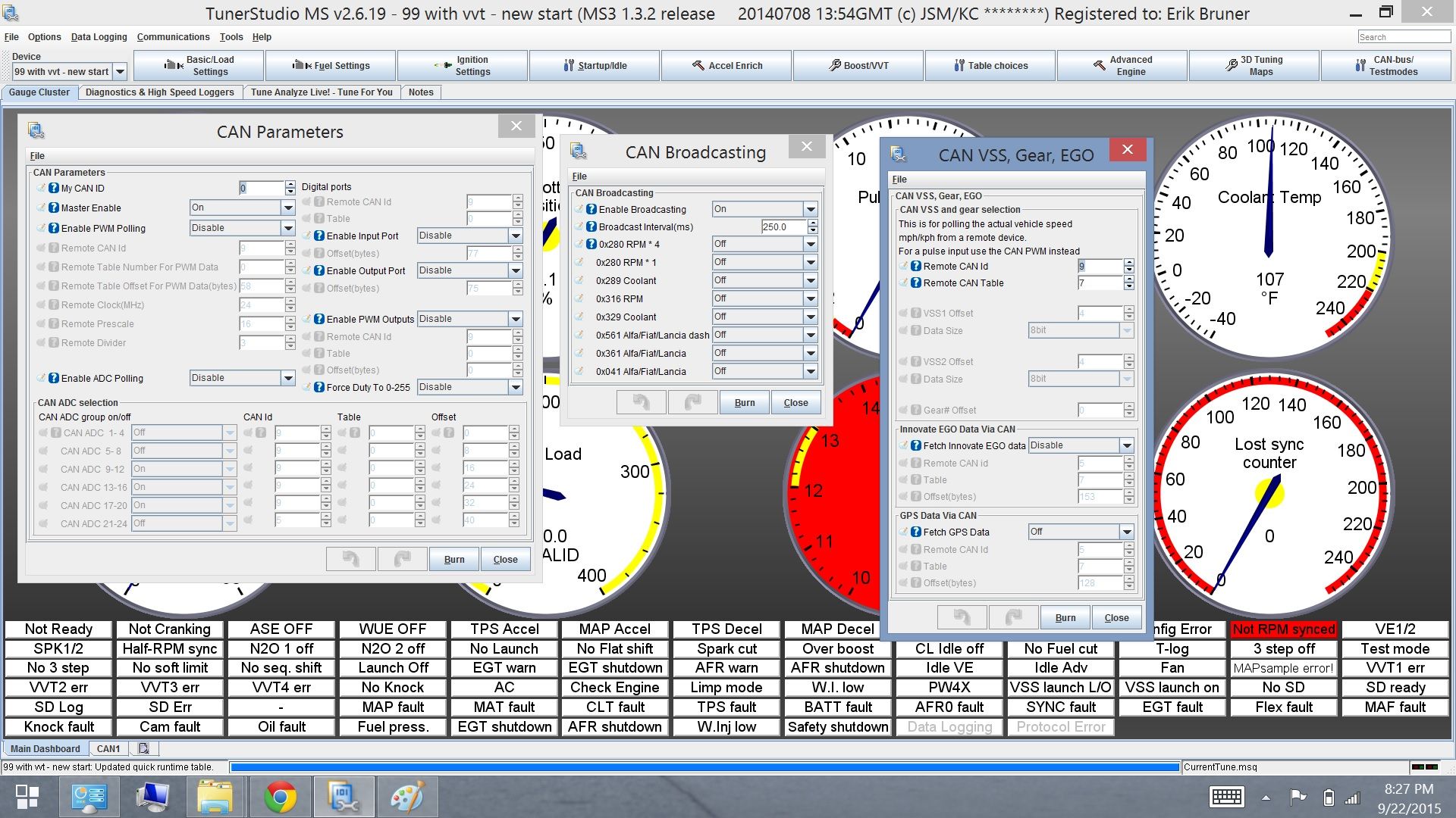
The only guide I have is for firmware 1.4 (here). Page 18/19 in that document seems to be what I'm looking for... but the settings in firmware 1.3.2 are very different.
I'm reluctant to flash to that firmware at the moment because we're only a week before the Miata's at Mazda raceway event and at the moment the car is running. Which is a good thing.
Pictures of the settings I have to work with.
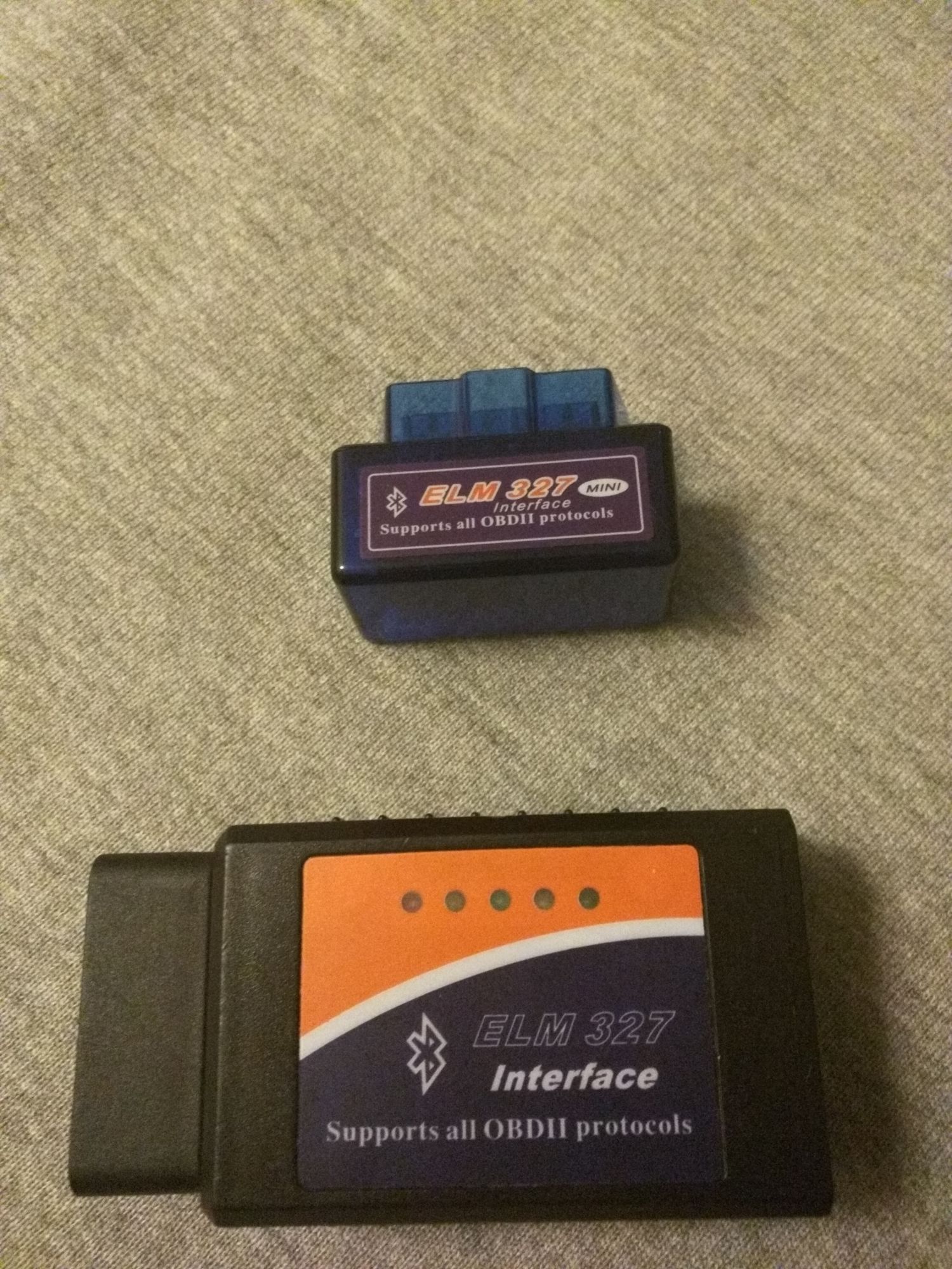
pictures of the adapters i have
If anyone has a link to where i can read about this it would be appreciated. I am not looking to set it up for can ego over the can bus... once I get the regular settings down I'll get crazy and dig into that.
The only guide I have is for firmware 1.4 (here). Page 18/19 in that document seems to be what I'm looking for... but the settings in firmware 1.3.2 are very different.
I'm reluctant to flash to that firmware at the moment because we're only a week before the Miata's at Mazda raceway event and at the moment the car is running. Which is a good thing.
Pictures of the settings I have to work with.
pictures of the adapters i have
0
09-23-2015, 09:57 AM
#89
Senior Member
Join Date: May 2011
Posts: 638
Total Cats: 76
Not for the moment. I am going to do one last event with the analog wideband input direct to the ms3 then I am going to convert to digital through the can module.
My goal is to get the adapter setup just outputting data to the ms3 for now so I can play with data logging (for video overlay) at this event. Just sort of a proof of concept before I dig in, reflash the firmware, go to the digital wb/02 and do a re-tune (if necessary).
-E
My goal is to get the adapter setup just outputting data to the ms3 for now so I can play with data logging (for video overlay) at this event. Just sort of a proof of concept before I dig in, reflash the firmware, go to the digital wb/02 and do a re-tune (if necessary).
-E
0
10-29-2015, 08:46 AM
#91

How much different should the instructions be for setting up the CAN wideband module on a DIYPNP as opposed to MS3 Basic?
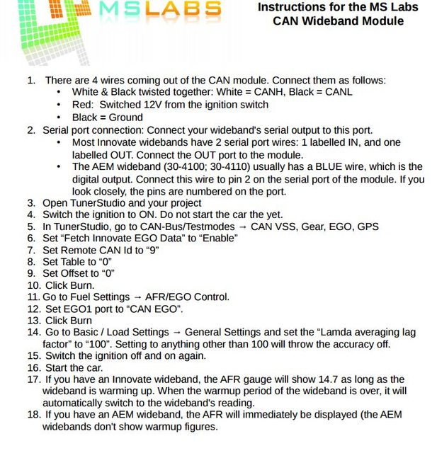
The instructions I got look like this:
And I'm having trouble because my CAN parameters look like this:
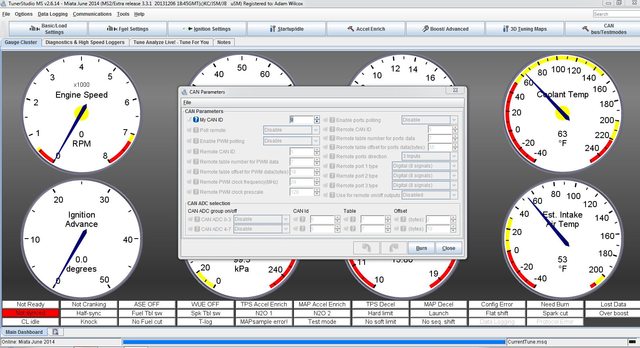
So I can't set �Fetch Innovate EGO Data� to �Enable� like it says in step 6. I've tried enabling some of the choices that are available, entering the given port, table, and offset settings, but that hasn't gotten me anywhere.
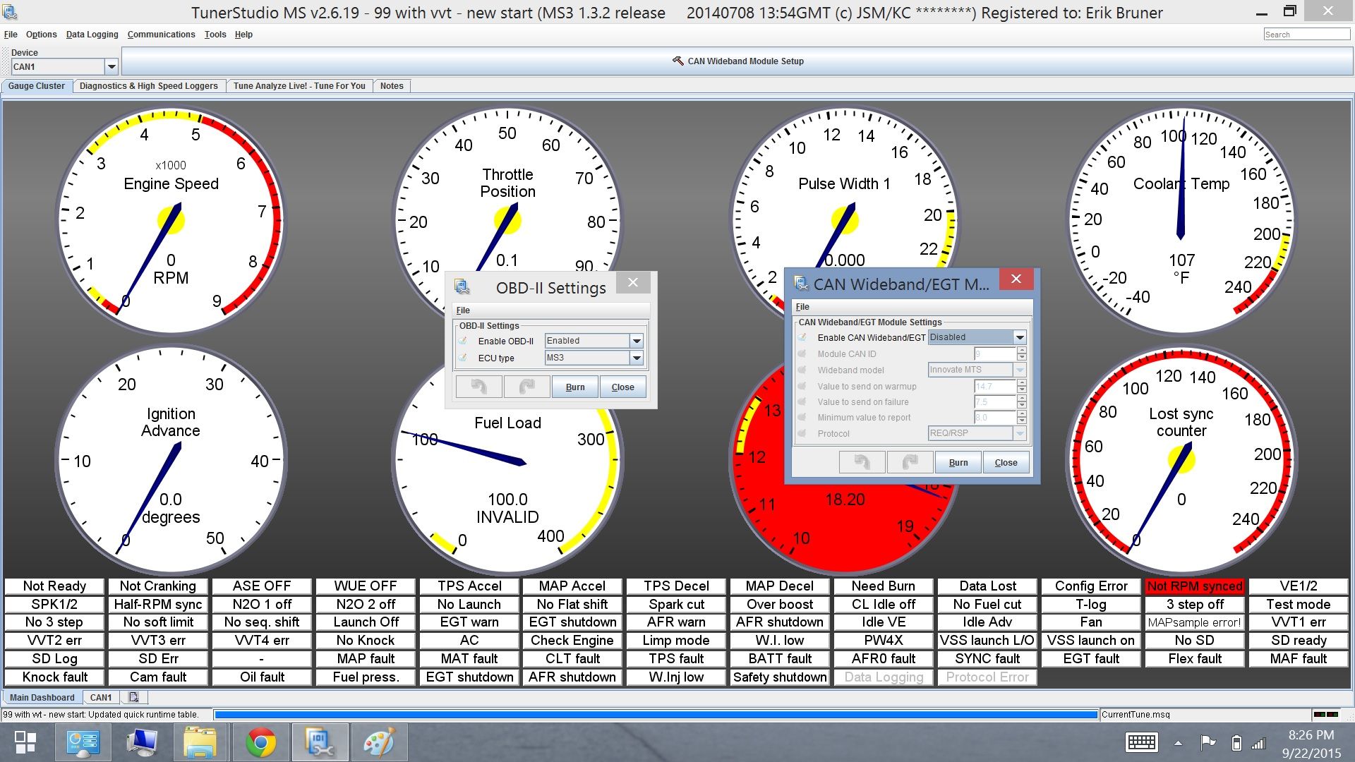
Similarly, there's no "CAN EGO" option under EGO1 port in AFR/EGO Control, only various ADC choices.
I'm pretty sure I have everything wired up correctly. I'm feeding my four module wires in through the DB15 port:
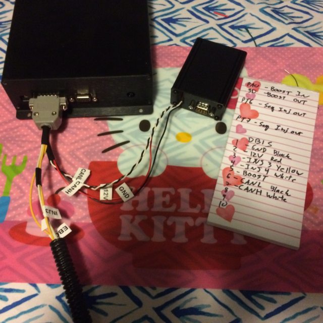
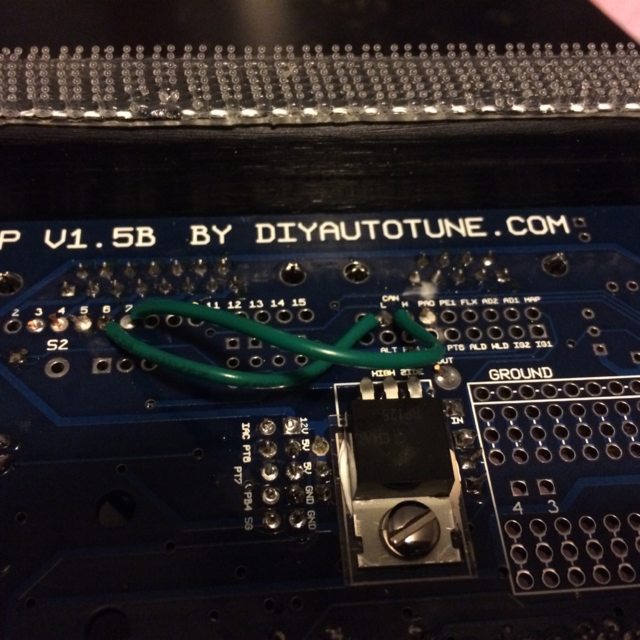
The black wire goes to DB15 pin 1, which is jumpered to GND on the main board. The red wire goes to pin 2 and 12V. The twisted white wire goes to pin 7 and CANH, and the twisted black wire goes to pin 6 and CANL like so:
I've got both the module and the DIYPNP hooked up in the car with the MTX-L serial cable running from the output port off the gauge to DB9 port on the CAN module.
What am I missing here?
The instructions I got look like this:
And I'm having trouble because my CAN parameters look like this:
So I can't set �Fetch Innovate EGO Data� to �Enable� like it says in step 6. I've tried enabling some of the choices that are available, entering the given port, table, and offset settings, but that hasn't gotten me anywhere.
Similarly, there's no "CAN EGO" option under EGO1 port in AFR/EGO Control, only various ADC choices.
I'm pretty sure I have everything wired up correctly. I'm feeding my four module wires in through the DB15 port:
The black wire goes to DB15 pin 1, which is jumpered to GND on the main board. The red wire goes to pin 2 and 12V. The twisted white wire goes to pin 7 and CANH, and the twisted black wire goes to pin 6 and CANL like so:
I've got both the module and the DIYPNP hooked up in the car with the MTX-L serial cable running from the output port off the gauge to DB9 port on the CAN module.
What am I missing here?
0
10-29-2015, 10:58 AM
#92
Elite Member

Thread Starter
iTrader: (10)
Join Date: Jun 2006
Location: Athens, Greece
Posts: 5,977
Total Cats: 356
1) Set "Master Enable" to "Enable"
2) Set CAN ADC 0-3 to "Enable".
3) In the row for CAN ADC 0-3, set CAN ID to 9, table to 0, offset to 0.
In the EGO Control, set the port to Remote ADC0.
2) Set CAN ADC 0-3 to "Enable".
3) In the row for CAN ADC 0-3, set CAN ID to 9, table to 0, offset to 0.
In the EGO Control, set the port to Remote ADC0.
0
10-29-2015, 09:22 PM
#93
When I do that, my TunerStudio AFR reading goes pegged at full rich while the gauge continues to give a credible reading.
0
10-30-2015, 05:37 AM
#94
Elite Member
Thread Starter
iTrader: (10)
Join Date: Jun 2006
Location: Athens, Greece
Posts: 5,977
Total Cats: 356
Make sure you've switched the ignition off and on again. If it still doesn't give a reading, load the .ini file and check that the module is configured for your specific wideband.
0
10-30-2015, 08:06 AM
#95
Reading what you wrote above, are you saying the CAN module has/needs it's own .ini file? If so, where do I get that file? Under the CAN tab in Project Properties I notice there's a place to load an .ini file if I add a CAN device on ADC0.
I can open the .ini text file for the Megasquirt, it reads code that's mostly a mystery to me. If this is the .ini file you mean, what do I need to look for and change in here?
Thanks for your help and patience on this.
0
10-30-2015, 10:25 AM
#96
Elite Member
Thread Starter
iTrader: (10)
Join Date: Jun 2006
Location: Athens, Greece
Posts: 5,977
Total Cats: 356
The most important bit - is the module connected to the "OUT" port on the MTX-L?
Also, if you open the module, there are 4 LEDs inside: red (12V), green (5V), and two blue (CAN and Serial).
The red and green should be on.
CAN and serial should be blinking, indicating activity.
Please confirm all of the above.
Also, if you open the module, there are 4 LEDs inside: red (12V), green (5V), and two blue (CAN and Serial).
The red and green should be on.
CAN and serial should be blinking, indicating activity.
Please confirm all of the above.
0
10-30-2015, 10:28 AM
#97
The most important bit - is the module connected to the "OUT" port on the MTX-L?
Also, if you open the module, there are 4 LEDs inside: red (12V), green (5V), and two blue (CAN and Serial).
The red and green should be on.
CAN and serial should be blinking, indicating activity.
Please confirm all of the above.
The red and green should be on.
CAN and serial should be blinking, indicating activity.
Please confirm all of the above.
0
11-01-2015, 04:22 AM
#100
I discovered I had CANL and CANH reversed at my DB15 connector. Corrected that and the CAN LED is still solid blue. Visually, I see no shorts or solder problems. I re-checked continuity using a multimeter and I'm finding that I get 120 ohms across the CANH and CANL pins on the MS board. Does this indicate a short, or is that part of the MS boards internal CAN circuitry?
0


