
Aerodynamic Discussion Thread

 05-20-2013, 11:14 AM
#142
Supporting Vendor

iTrader: (3)

Join Date: Jul 2006
Location: San Diego
Posts: 3,303
Total Cats: 1,216
It might just be the angle that picture is taken from making it look like the splitter isn't horizontal to the ground.
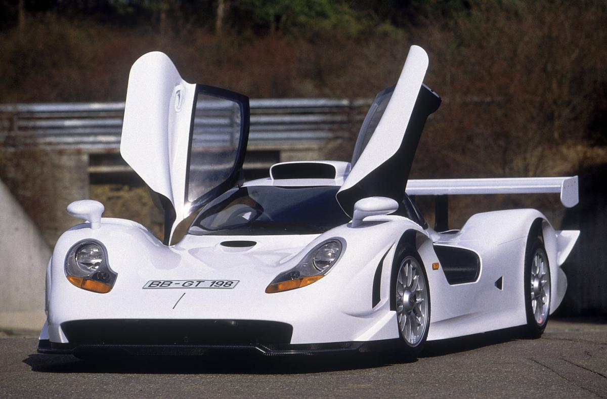
As for those canards on the mclaren, it looks like those are partially designed to serve as tire spats, which might account for the steep angle if they wanted to cover the front area of the tire.
-Ryan
As for those canards on the mclaren, it looks like those are partially designed to serve as tire spats, which might account for the steep angle if they wanted to cover the front area of the tire.
-Ryan


Reply
 0
0

0
05-20-2013, 02:51 PM
#143
Elite Member

iTrader: (2)
Join Date: May 2008
Location: Portland, Oregon
Posts: 3,468
Total Cats: 365
No, they don't appear to be there to cover the tire, as the other elements of the nose are completely covering the tire.
I'm going to make a WAG here and say there's no way we can really determine what the specific function of these canards on this car is without CFD results.


I'm going to make a WAG here and say there's no way we can really determine what the specific function of these canards on this car is without CFD results.
Reply
0
0
 05-20-2013, 11:38 PM
#145
Junior Member

Join Date: Dec 2012
Location: Indianapolis
Posts: 74
Total Cats: 45
You do not want to run the splitter at an angle, especially up unless you want to create lift.
Reply
0
0
 05-21-2013, 01:59 AM
#148
Senior Member

Join Date: Dec 2010
Location: Auckland, NZ
Posts: 992
Total Cats: 57
You do not want to run the splitter at an angle, especially up unless you want to create lift
Also due to the fact that the McLaren photos shown above has the front edge of the splitter on an angle/raised higher at the front. I would say by about 2 cm/1 inch.....
You see the edge of it, underneath it would most probably have diffusors etc. I.e. it's most probably not just a flat plane with that angle.
Reply
0
0
05-21-2013, 02:14 AM
#149
Elite Member
iTrader: (2)
Join Date: May 2008
Location: Portland, Oregon
Posts: 3,468
Total Cats: 365
I believe the photo is deceiving. We don't have a good horizontal reference. The suspension is at full droop. I can't find a good side shot of the GT3 on the ground. But the splitter looks to be horizontal to me.

Reply
0
0
 05-21-2013, 12:30 PM
#151
Junior Member
Join Date: Dec 2012
Location: Indianapolis
Posts: 74
Total Cats: 45
Multiple element wings have a greater induced drag than a single element wings. Multiple elements are used when single elements do not make the downforce required.
Reply
0
0
05-21-2013, 01:00 PM
#152
I'll have to try and find the study. My main computer just got a massive upgrade (yay 4 times as much ram and better processor) and HD wipe (now I have room for a linux partition for open FOAM) so my CFD studies are hiding somewhere on my backups. The issue was trying to hit my 450 lbs @ 60mph goal required a pretty stupid, massive, huge AOA, tons of camber single element, where as the dual element was able to straight up more efficiently use the air, less flow separation and that jazz.
Reply
0
0
05-21-2013, 02:35 PM
#154
Junior Member
Join Date: Dec 2012
Location: Indianapolis
Posts: 74
Total Cats: 45
I'll have to try and find the study. My main computer just got a massive upgrade (yay 4 times as much ram and better processor) and HD wipe (now I have room for a linux partition for open FOAM) so my CFD studies are hiding somewhere on my backups. The issue was trying to hit my 450 lbs @ 60mph goal required a pretty stupid, massive, huge AOA, tons of camber single element, where as the dual element was able to straight up more efficiently use the air, less flow separation and that jazz.

Also what turbulence model and wall functions are you using in OpenFoam? Depending on that, the numbers can be wrong.
Reply
0
0
05-21-2013, 02:48 PM
#155
But that is comparing apples and oranges. You are comparing the efficiency of a stalled single element to a non-stalled multi-element wing. When the wing stalls, the drag shoots up and lift/downforce decreases. So of course it will be more efficient. You went multi-element wing since you needed more downforce which is what I said earlier
Also what turbulence model and wall functions are you using in OpenFoam? Depending on that, the numbers can be wrong.
Also what turbulence model and wall functions are you using in OpenFoam? Depending on that, the numbers can be wrong.
Reply
0
0
05-21-2013, 05:00 PM
#156
Junior Member
Join Date: Dec 2012
Location: Indianapolis
Posts: 74
Total Cats: 45
I dont want to be argumentative because I cetainly have no experience to back this up but...this statement seems very hard to comprehend. I would think many performance road cars have up angled splitters in order to retain some form of obstruction clearance (minimal though that may be...)
Also due to the fact that the McLaren photos shown above has the front edge of the splitter on an angle/raised higher at the front. I would say by about 2 cm/1 inch.....
- Reading Niklasfalk's comment, quite possible but that would then mean you can run an angled spitter so long as you have some form of diffuser underneath....however it does appear to be flat.
Used COSMOS for that stuff. Haven't had a computer besides my netbook with linux so I haven't used open FOAM yet. I did have some problems getting COSMOS to react as expected at first until I realized I had my goals set wrong. I'm also not going to claim my wing makes 450 lbs @ 60mph, the model says it does but it was analyzed off the car, and I dont really trust COSMOS to be that accurate. It certainly does make some downforce in real life, but its unmeasured.
Reply
0
0
05-22-2013, 12:52 AM
#158
Senior Member

Join Date: Aug 2009
Location: melbourne aus
Posts: 515
Total Cats: 92
Having the splitter turning up at the leading edge is good if you have a flat floor and rear diffuser. You need to feed the air to the underbody. If no flat floor. I would block as much air going under as possible.
Reply
0
0
05-22-2013, 11:41 AM
#159
Supporting Vendor
iTrader: (3)
Join Date: Jul 2006
Location: San Diego
Posts: 3,303
Total Cats: 1,216
A raised center section for the splitter would be better than the leading edge just rounding upwards I would think.
I am with plucas, I think that at least in 99.9% of applications, unless there's some other strange elements going on that make some sort of use of it, you don't want a splitter angled up in front. Especially since the splitter's purpose is to provide downforce, which is does well when horizontal, and even better when angled very slightly down in the front (splitter bottom surface can act as a diffuser)
-Ryan
Reply
0
0
05-22-2013, 12:33 PM
#160
Senior Member
iTrader: (1)

Join Date: Dec 2008
Location: Manassas, Virginia
Posts: 1,242
Total Cats: 57
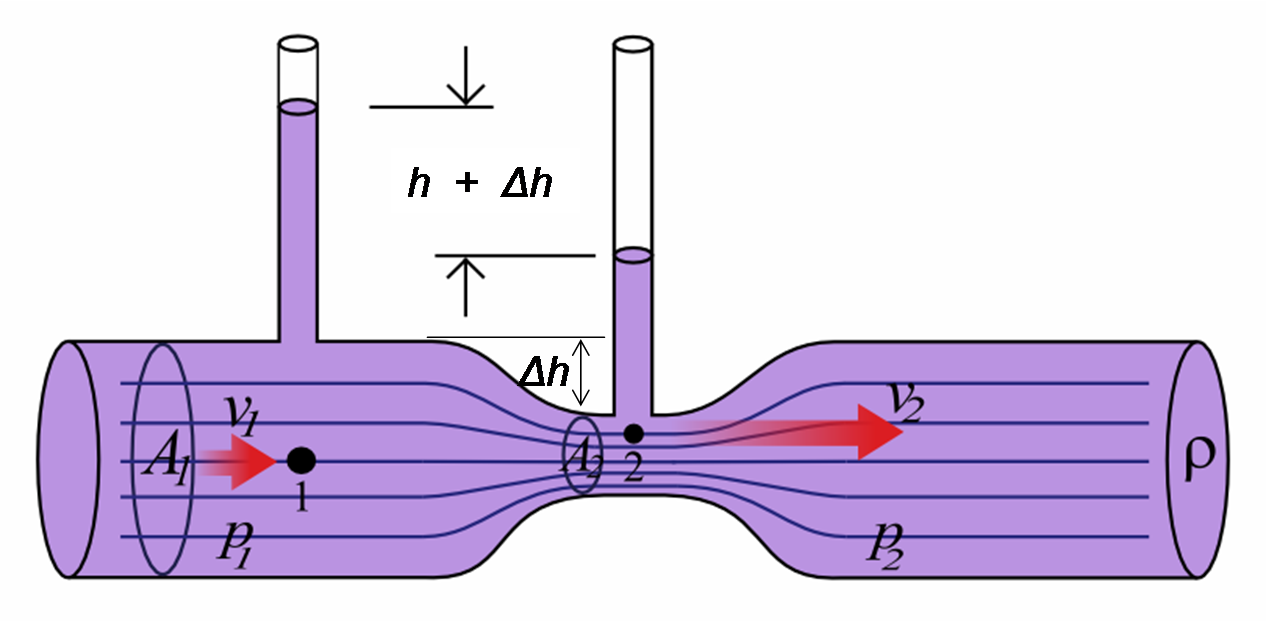
Wouldn't a raised leading edge (to a degree) enhance the venturi shape (which is the basis of how downforce is made through the ground effect) more than it creates lift?
Reply
0
0


