
Hornetball's Build


Thread Starter
Elite Member
iTrader: (4)
Joined: Mar 2008
Posts: 6,301
Total Cats: 697
From: Granbury, TX
By trim map change I meant-
The hydra has a 3D map that allows you to add or remove fuel and timing if signal is present (ground or hot) on one of the hydra's inputs. That hydra input is typically wired to your failsafes (flow sensor, float sensor). That way if you have no flow or are out of water, your 3D maps turn off and you do not blow up your motor.
The hydra has a 3D map that allows you to add or remove fuel and timing if signal is present (ground or hot) on one of the hydra's inputs. That hydra input is typically wired to your failsafes (flow sensor, float sensor). That way if you have no flow or are out of water, your 3D maps turn off and you do not blow up your motor.
Reply
 0
0

0
Thread Starter
Elite Member
iTrader: (4)
Joined: Mar 2008
Posts: 6,301
Total Cats: 697
From: Granbury, TX
Your welcome on the "how to" pics. I always appreciate it when people post those, so I thought I would return the favor.
Reply
0
0

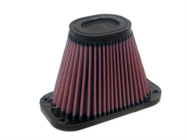
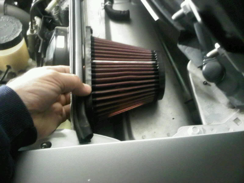
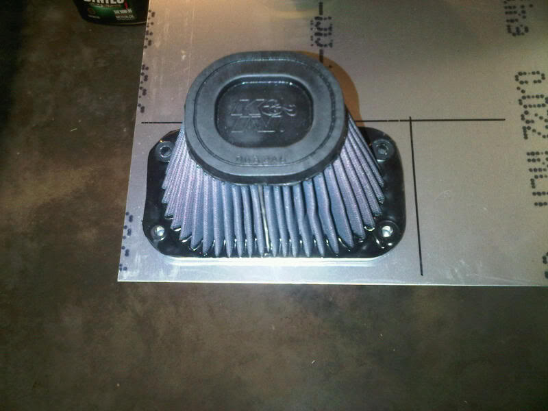
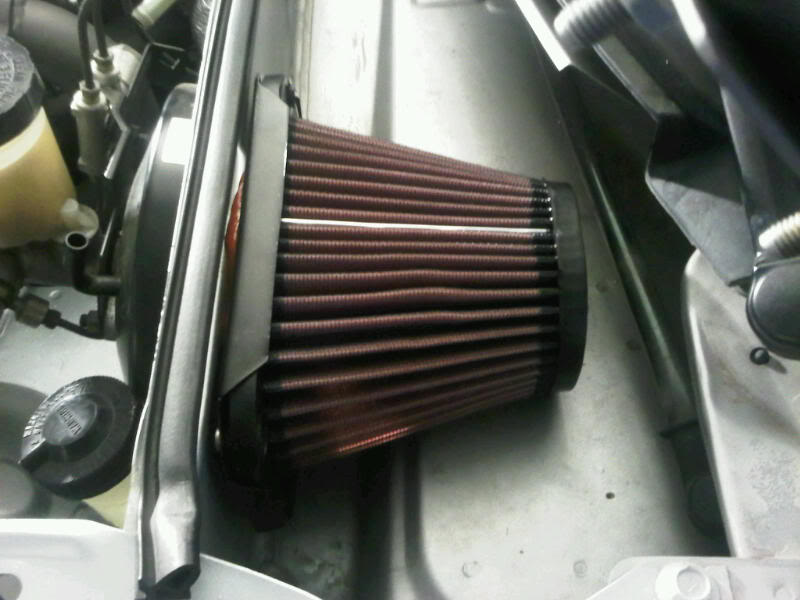
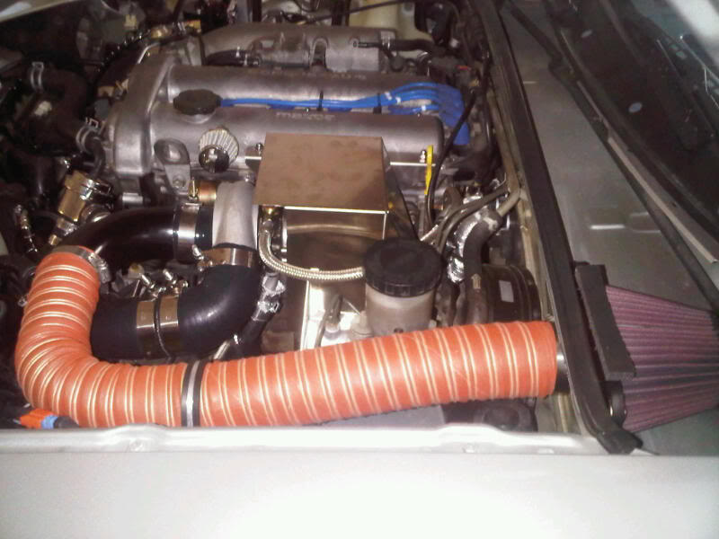
That K&N looks a bit small. I had an old K&N that was double that size that collapsed at about 12psi. It was old and tired, I'd watch for signs of stress deformation. Somebody may chime in that it's not a concern, but I'm pretty sure most filters have a CFM rating on them... might want to do the math and see if it's big enough. If you start to outflow it, you run the risk of collapsing your intake... it looks fairly rigid, but the amount of "suction" the turbo will pull could be enough to hurt the hose.
Reply
0
0
Thread Starter
Elite Member
iTrader: (4)
Joined: Mar 2008
Posts: 6,301
Total Cats: 697
From: Granbury, TX
That K&N looks a bit small. I had an old K&N that was double that size that collapsed at about 12psi. It was old and tired, I'd watch for signs of stress deformation. Somebody may chime in that it's not a concern, but I'm pretty sure most filters have a CFM rating on them... might want to do the math and see if it's big enough. If you start to outflow it, you run the risk of collapsing your intake... it looks fairly rigid, but the amount of "suction" the turbo will pull could be enough to hurt the hose.
Thanks for the heads up. And hang in there. There is life after the Navy.
Reply
0
0

That K&N looks a bit small. I had an old K&N that was double that size that collapsed at about 12psi. It was old and tired, I'd watch for signs of stress deformation. Somebody may chime in that it's not a concern, but I'm pretty sure most filters have a CFM rating on them... might want to do the math and see if it's big enough. If you start to outflow it, you run the risk of collapsing your intake... it looks fairly rigid, but the amount of "suction" the turbo will pull could be enough to hurt the hose.
The black rubber on the thing was frikken soft from the engine bay heat!!! When the car has been off for a while, it is very very stiff.
Reply
0
0
Thread Starter
Elite Member
iTrader: (4)
Joined: Mar 2008
Posts: 6,301
Total Cats: 697
From: Granbury, TX
OK, Samnavy made it abundantly clear that I was being lazy and just "winging it" with my air filter selection. So, I dug in. I was able to find decent design data on the internet related to filter sizing.
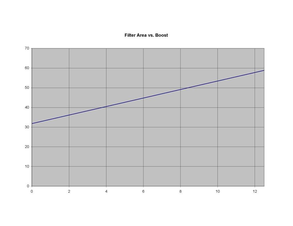
The first equation comes from K&N and relates boost, CID and RPM to gauze filter area. Equation is:
Area (in^2) = ( Boost (PSI) / 14.7 + 1 ) x CID x RPM / 20839
Plotted for a Miata 1.6L (97.5CID and 6800RPM), this gives:
The second equation is a bit more complex, but I wanted a sanity check on K&N's equation. It consists of the following relationships:
CFM as a function of HP, Air:Fuel Ratio and BSFC:
CFM = ( AFR x HP x BSFC ) / 4.59
Area as a function of CFM (for a 1.5"H2O pressure drop) based upon 6.07CFM/in^2 (gauze) or 4.95CFM/in^2 (paper).
Plotted for a gauze filter on a turbo Miata (AFR = 12.5:1 and BSFC = 0.55), this gives:
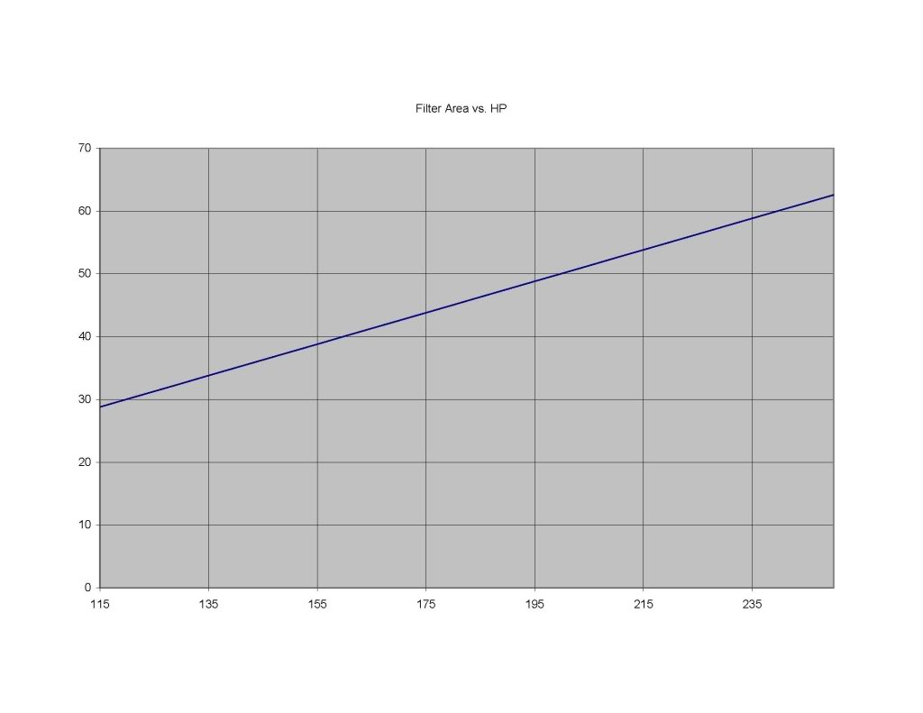
The two methods agree pretty closely, which gives good confidence.
Now to get on with sizing. The RU-3780 that I chose has a filter area of only 32in^2. According to the charts, this would be sufficient for, well, a stock NA Miata!! Yikes!! Thank you Sam.
My goals aren't extreme. I'm shooting for ~10psi and 200HP with water injection. 10psi gives a filter size of 53in^2 while 200HP gives a filter size of 49in^2. Going back to K&N's website and scouring based upon these goals and my limited space, I've decided to order a PL-1598.
This filter has an area of 58in^2. In addition, it mounts via bolts in the base instead of a flange which actually works better for my application. Filter on order. Happier camper!
Here's my spreadsheet if anyone is interested.
The first equation comes from K&N and relates boost, CID and RPM to gauze filter area. Equation is:
Area (in^2) = ( Boost (PSI) / 14.7 + 1 ) x CID x RPM / 20839
Plotted for a Miata 1.6L (97.5CID and 6800RPM), this gives:
The second equation is a bit more complex, but I wanted a sanity check on K&N's equation. It consists of the following relationships:
CFM as a function of HP, Air:Fuel Ratio and BSFC:
CFM = ( AFR x HP x BSFC ) / 4.59
Area as a function of CFM (for a 1.5"H2O pressure drop) based upon 6.07CFM/in^2 (gauze) or 4.95CFM/in^2 (paper).
Plotted for a gauze filter on a turbo Miata (AFR = 12.5:1 and BSFC = 0.55), this gives:
The two methods agree pretty closely, which gives good confidence.
Now to get on with sizing. The RU-3780 that I chose has a filter area of only 32in^2. According to the charts, this would be sufficient for, well, a stock NA Miata!! Yikes!! Thank you Sam.
My goals aren't extreme. I'm shooting for ~10psi and 200HP with water injection. 10psi gives a filter size of 53in^2 while 200HP gives a filter size of 49in^2. Going back to K&N's website and scouring based upon these goals and my limited space, I've decided to order a PL-1598.
This filter has an area of 58in^2. In addition, it mounts via bolts in the base instead of a flange which actually works better for my application. Filter on order. Happier camper!
Here's my spreadsheet if anyone is interested.
Reply
1
1
Thread Starter
Elite Member
iTrader: (4)
Joined: Mar 2008
Posts: 6,301
Total Cats: 697
From: Granbury, TX
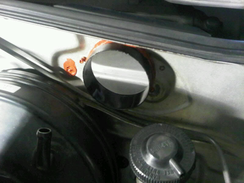
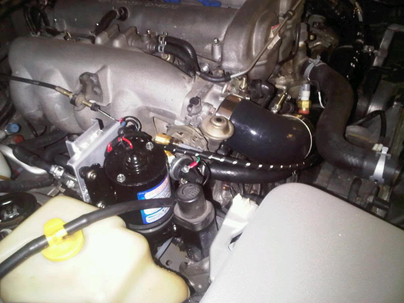
Got home with a bit of extra energy and decided to piddle in the garage. Mounting WI components to the washer fluid tank seemed like just the ticket. Here's what I did:
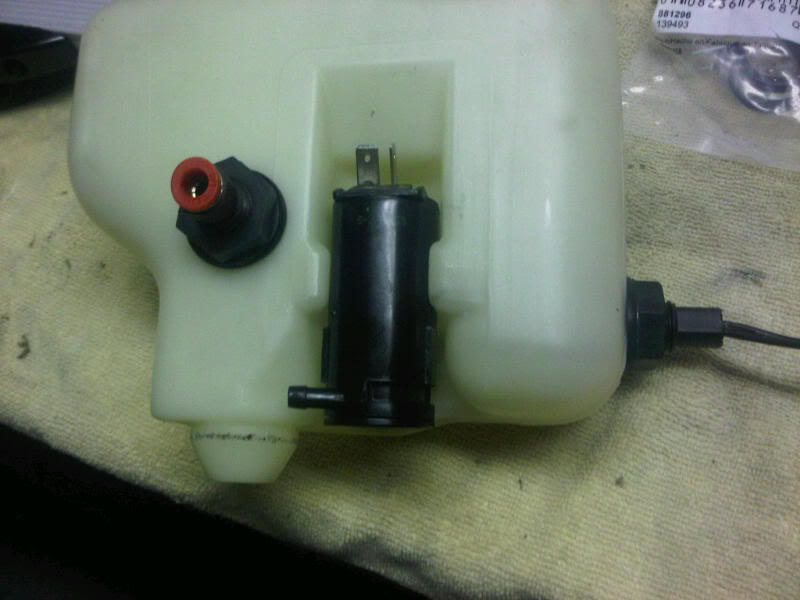
Intake above the float switch level!! I had a 50/50 chance and I FUBAR'd it. Anyway, $15 on E-bay is getting me another tank. Based upon this result, I decided to knock off working on the car for the night.

Intake above the float switch level!! I had a 50/50 chance and I FUBAR'd it. Anyway, $15 on E-bay is getting me another tank. Based upon this result, I decided to knock off working on the car for the night.
Reply
0
0

Thread Starter
Elite Member
iTrader: (4)
Joined: Mar 2008
Posts: 6,301
Total Cats: 697
From: Granbury, TX
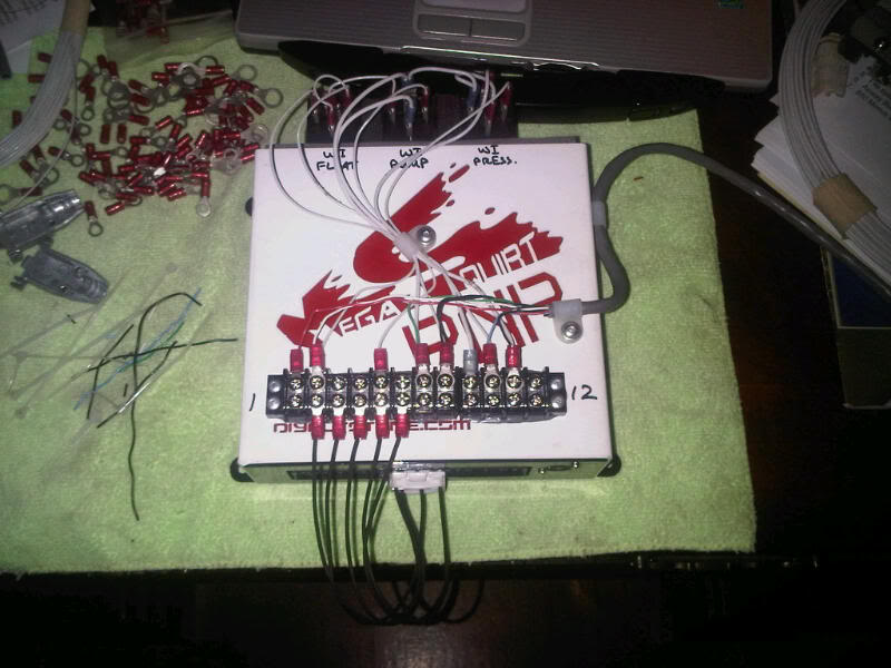
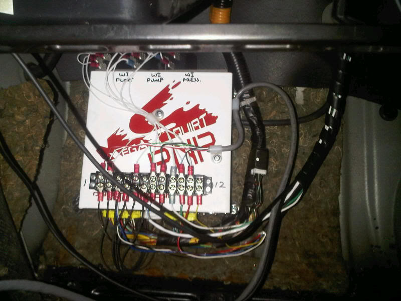
MSPNP chassis makes a decent place to mount terminal blocks and relays. The white color even allows marking with a permanent marker.
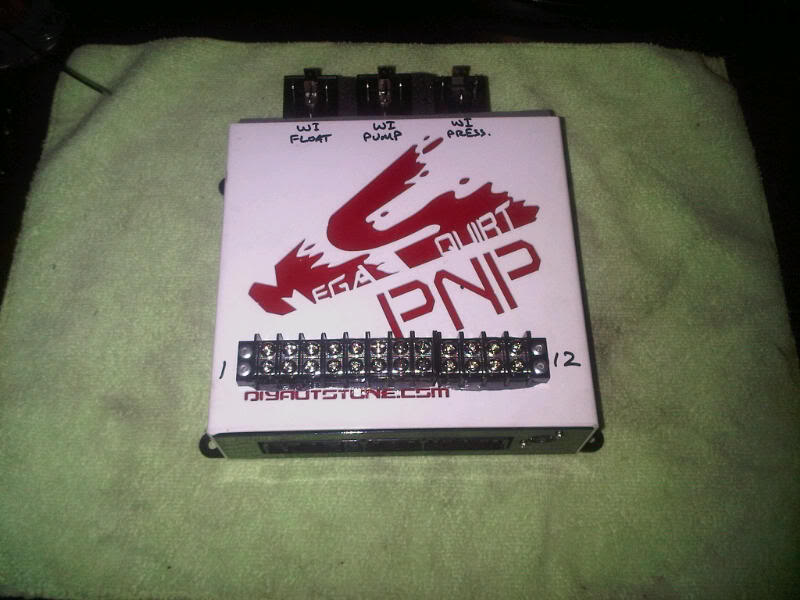
So, why make detailed drawings of the circuits? Two reasons:
1. Future maintenance
2. Easier installation
Here, I've just finished making about 70% of my connections. I did it comfortably sitting at a desk. Sure beats the normal electronic yoga.
So, why make detailed drawings of the circuits? Two reasons:
1. Future maintenance
2. Easier installation
Here, I've just finished making about 70% of my connections. I did it comfortably sitting at a desk. Sure beats the normal electronic yoga.
Reply
0
0
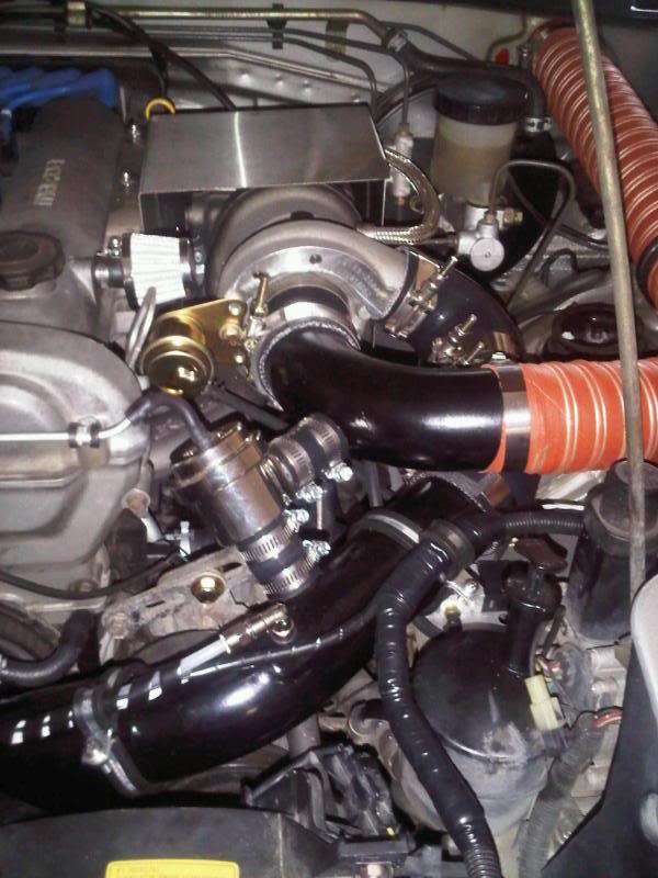
Nicely documented, sanitary build. Great especially for a Greddy.
My two cents: You're going to want to replace that downpipe. When you do, the new one will be big enough that you'll have to notch that heat shield for clearance. I just drilled out some of the spot welds and made a cut, and pulled it away from the downpipe. It's all on the back side of the shield so no one can tell, either.
For the drain, I can tell you I'm regretting getting a straight-down fitting for my drain hose. Even with aluminized cotton sleeving (same as you used on your heater hoses) it only took about a year before the drain hose needed to be replaced. You'll either want to let the drain swing away from the manifold a tad, or if it is a straight-down drain see if you can extend the metal portion of it.
Reply
0
0
Thread Starter
Elite Member
iTrader: (4)
Joined: Mar 2008
Posts: 6,301
Total Cats: 697
From: Granbury, TX
Nicely documented, sanitary build. Great especially for a Greddy.
My two cents: You're going to want to replace that downpipe. When you do, the new one will be big enough that you'll have to notch that heat shield for clearance. I just drilled out some of the spot welds and made a cut, and pulled it away from the downpipe. It's all on the back side of the shield so no one can tell, either.
For the drain, I can tell you I'm regretting getting a straight-down fitting for my drain hose. Even with aluminized cotton sleeving (same as you used on your heater hoses) it only took about a year before the drain hose needed to be replaced. You'll either want to let the drain swing away from the manifold a tad, or if it is a straight-down drain see if you can extend the metal portion of it.
My two cents: You're going to want to replace that downpipe. When you do, the new one will be big enough that you'll have to notch that heat shield for clearance. I just drilled out some of the spot welds and made a cut, and pulled it away from the downpipe. It's all on the back side of the shield so no one can tell, either.
For the drain, I can tell you I'm regretting getting a straight-down fitting for my drain hose. Even with aluminized cotton sleeving (same as you used on your heater hoses) it only took about a year before the drain hose needed to be replaced. You'll either want to let the drain swing away from the manifold a tad, or if it is a straight-down drain see if you can extend the metal portion of it.
You're 100% correct on the straight-down fitting. I've applied heat to mine. It now has ~20-30� angle to get away from the manifold.
Reply
0
0

re: the heat shield
I let my larger downpipe break one of the spot welds, and when it did, I drilled it out and put a thick (.125"ish) washer between the two pieces of the heat shield, which solved my clearance issues. You can barely see the bolt in the picture i posted on page 2. This also misaligned the single mounting hole. I bolted a 2" strip of metal to rubber isolator and bolted that to bracket on the fender. That quickly stripped out, and required a 6" extension to get to easily, which I didn't always grab from my tool box. A cotter pin, spring, and a hair clip solved that, and makes it very quick to take off.
I let my larger downpipe break one of the spot welds, and when it did, I drilled it out and put a thick (.125"ish) washer between the two pieces of the heat shield, which solved my clearance issues. You can barely see the bolt in the picture i posted on page 2. This also misaligned the single mounting hole. I bolted a 2" strip of metal to rubber isolator and bolted that to bracket on the fender. That quickly stripped out, and required a 6" extension to get to easily, which I didn't always grab from my tool box. A cotter pin, spring, and a hair clip solved that, and makes it very quick to take off.
Reply
0
0

nice build!!! I like all the custom fabrication/brackets etc....looks great. I need to pick up some of that heatshielding material for myself, you just reminded me, thanks haha.
Reply
0
0
Thread Starter
Elite Member
iTrader: (4)
Joined: Mar 2008
Posts: 6,301
Total Cats: 697
From: Granbury, TX
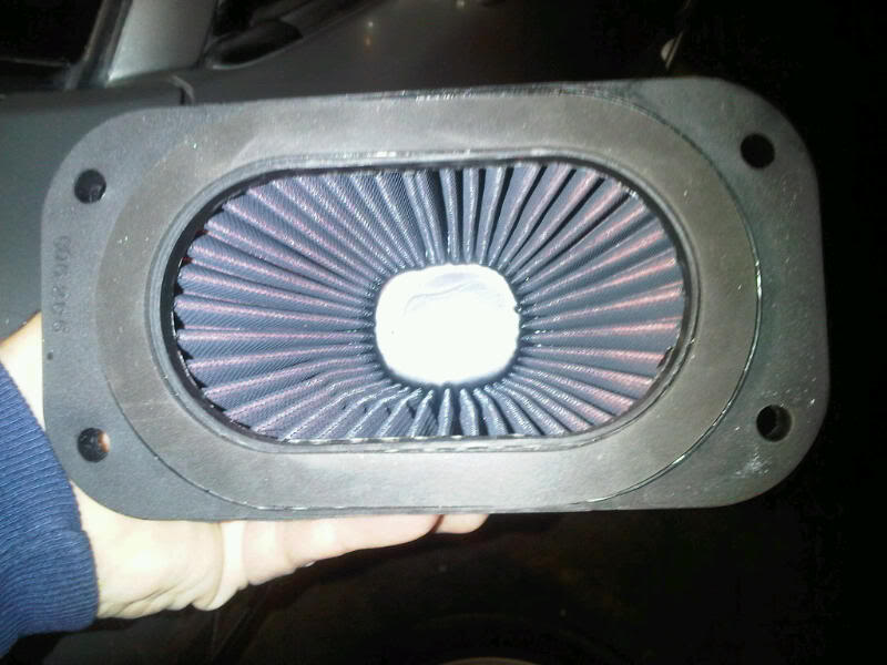
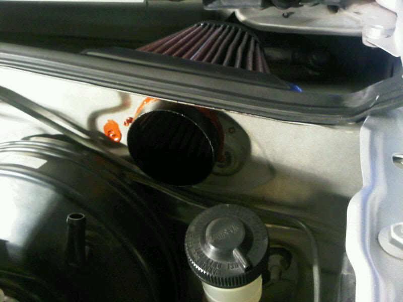
So, the PL-1598 came in. Now to mount it.
Darn thing fits like a glove. MUCH bigger than the RU-3780 I tried previously.
Here's the issue. It has a flat sealing gasket at its base. Unfortunately, the firewall area I'm mounting to is not flat (it is embossed for the wiper motor on RHD installations).
So, I begin constructing a filter mounting base from sheet aluminum.
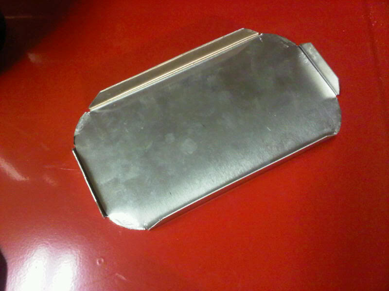
Cut out with ears bent. While the ears are useful for keeping the filter secure, their main function is to stiffen the base.
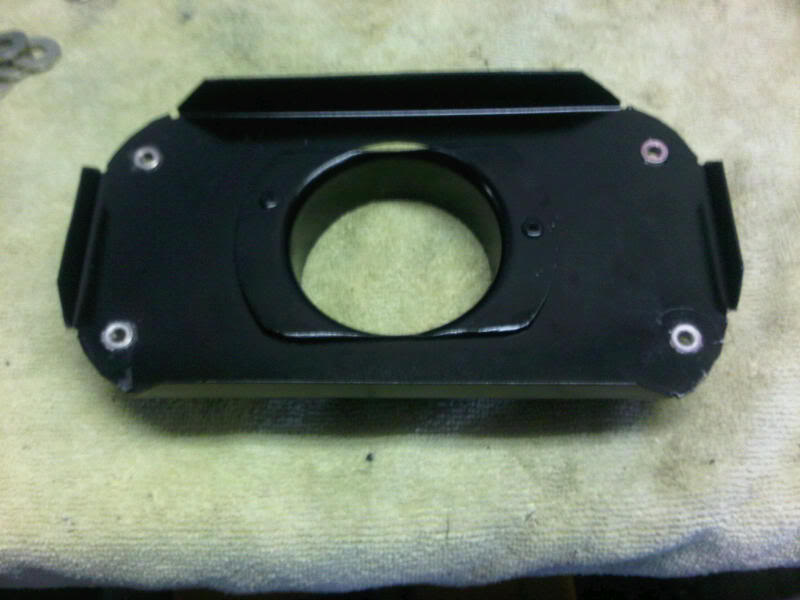
A bit more progress. I drilled a hole for the original duct flange that had been installed on the car. The flange has been trimmed top and bottom to allow the air filter gasket to seal against the base. 10-32 threadserts are installed at the corners to mount the filter.
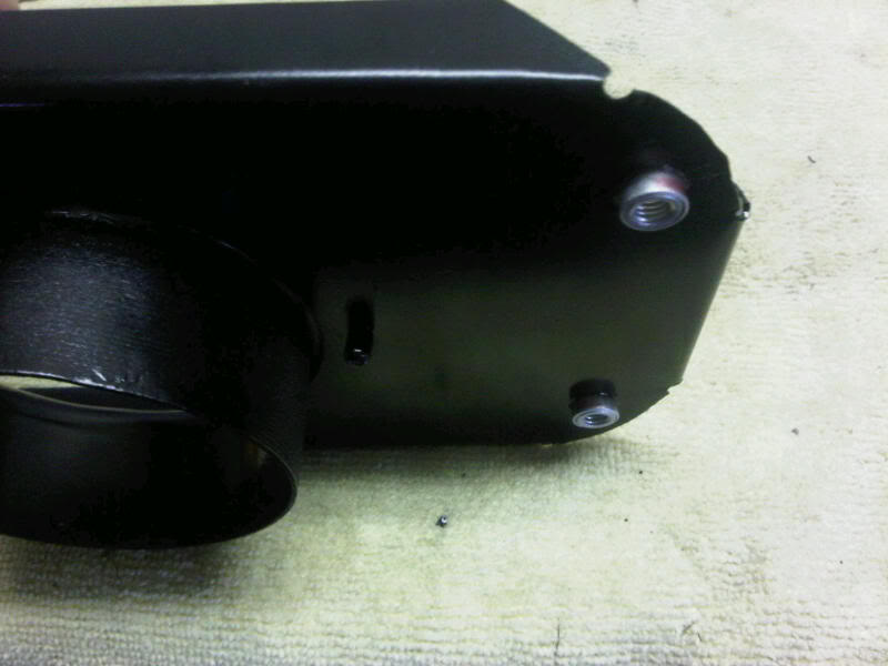
Close-up of the threadserts.
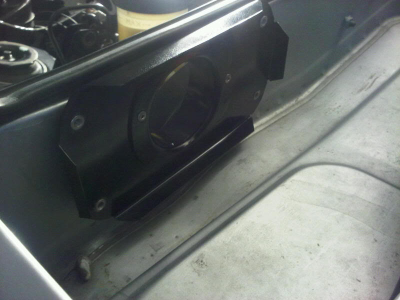
Mounted to the car. Two steel pop-rivets did the trick. Generous amounts of high-temp RTV provide sealing, damping and help secure the air filter base.
I think that turned out rather well!
Darn thing fits like a glove. MUCH bigger than the RU-3780 I tried previously.
Here's the issue. It has a flat sealing gasket at its base. Unfortunately, the firewall area I'm mounting to is not flat (it is embossed for the wiper motor on RHD installations).
So, I begin constructing a filter mounting base from sheet aluminum.
Cut out with ears bent. While the ears are useful for keeping the filter secure, their main function is to stiffen the base.
A bit more progress. I drilled a hole for the original duct flange that had been installed on the car. The flange has been trimmed top and bottom to allow the air filter gasket to seal against the base. 10-32 threadserts are installed at the corners to mount the filter.
Close-up of the threadserts.
Mounted to the car. Two steel pop-rivets did the trick. Generous amounts of high-temp RTV provide sealing, damping and help secure the air filter base.
I think that turned out rather well!
Reply
0
0
Thread Starter
Elite Member
iTrader: (4)
Joined: Mar 2008
Posts: 6,301
Total Cats: 697
From: Granbury, TX
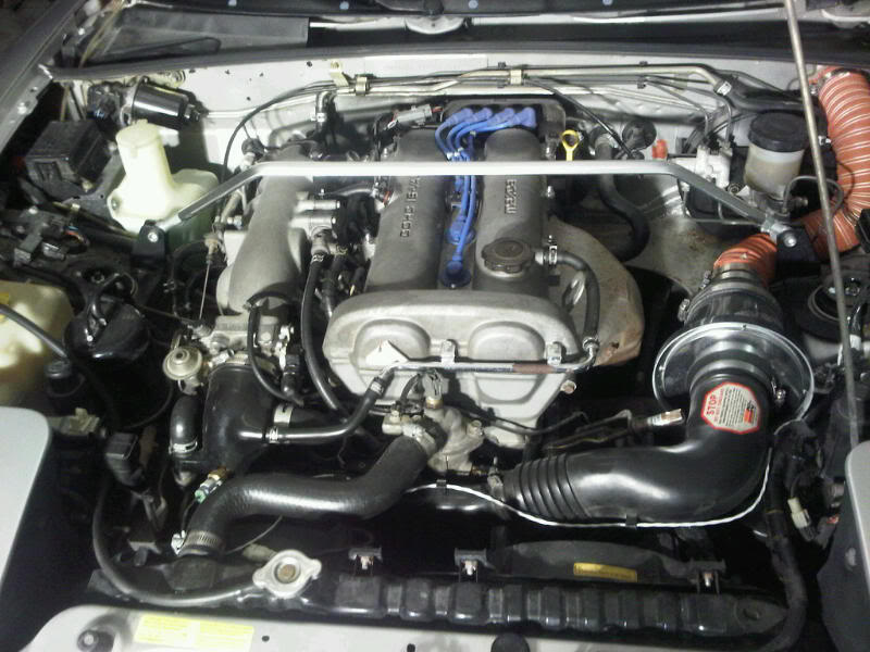
Wrapped up the under-hood work. Some pictures (starting from the driver's side):
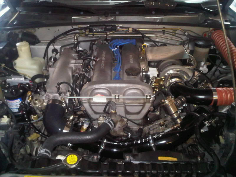
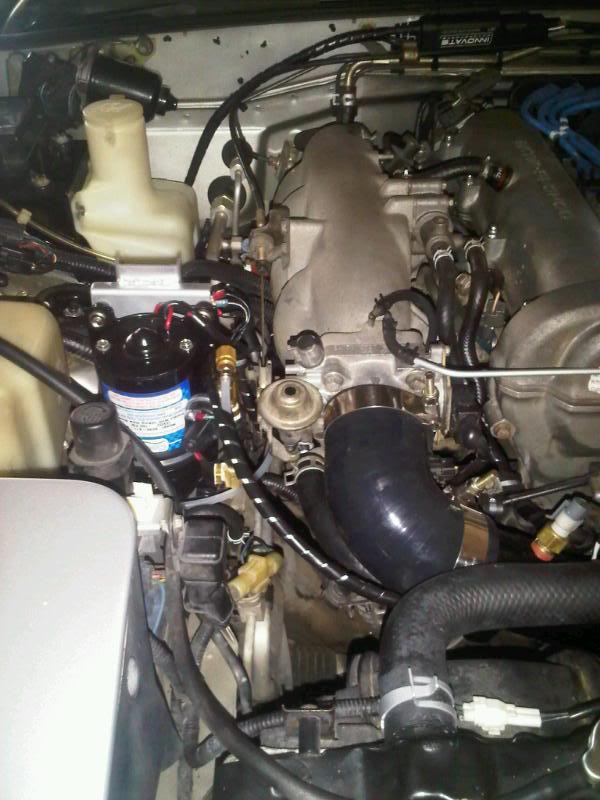
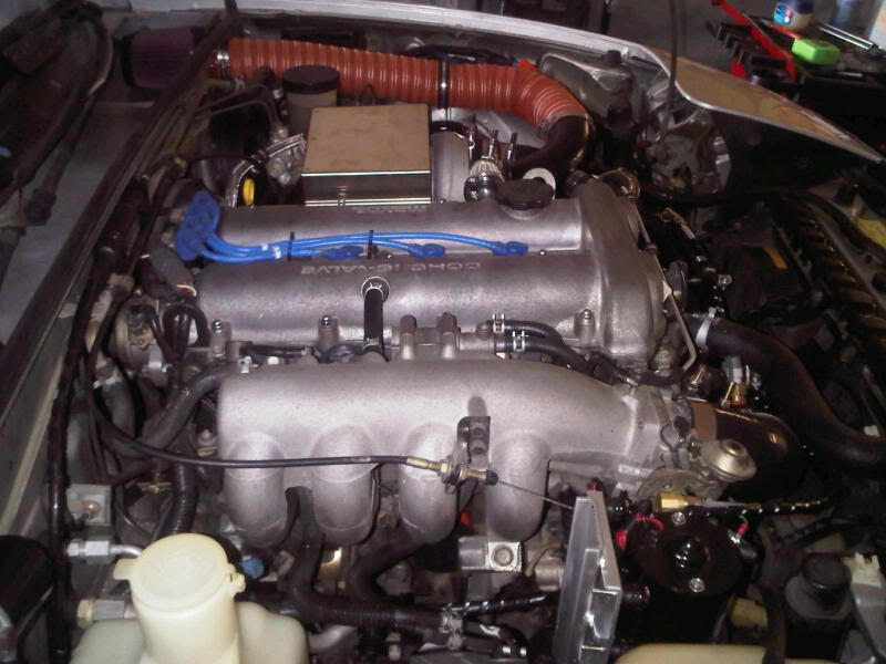
And, all engine compartment cabling is wired in:
Now, all I have left is some interior wiring, switches and gauges. Then, we'll see how it all works.
Just for giggles . . .
Before:
After:
And, all engine compartment cabling is wired in:
Now, all I have left is some interior wiring, switches and gauges. Then, we'll see how it all works.
Just for giggles . . .
Before:
After:
Reply
0
0
Thread Starter
Elite Member
iTrader: (4)
Joined: Mar 2008
Posts: 6,301
Total Cats: 697
From: Granbury, TX
So, this was the weekend for the final push towards boost!!! As they say, 90% done, 90% to go. Most of the final detail work had to do with wiring and electronics. Pics:
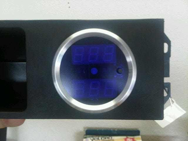
I purchased a VEI combined vacuum/boost and AFR gauge. I wanted those two parameters full time, but I wanted to keep from ricing the car too much. This gauge fit the bill.
Compact, rugged (billet aluminum) and made in the USA. What could be better?
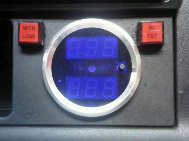
Installed with low water light and combination WI Test Switch and WI Pressure Light. See my schematics for how these work. Note that I was not able to use an OEM cluster light for low water. The 90 models did not have the OEM light.
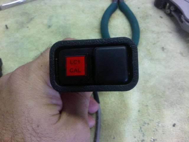
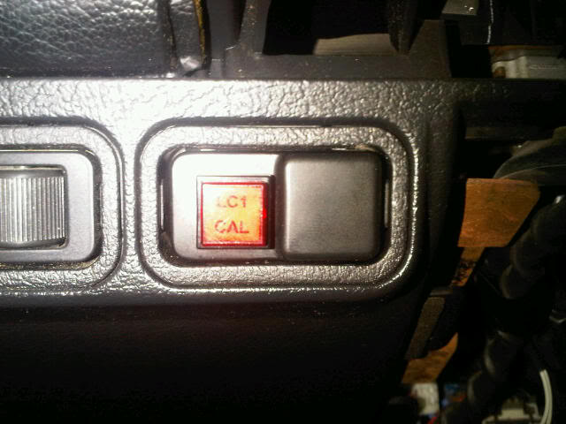
LC-1 combination calibration switch and status LED. The labels for all these switches were made from clear mailing labels with 9 point Arial type. The switch caps pop off for convenient labeling. These types of switches are available from Digikey or Mouser.
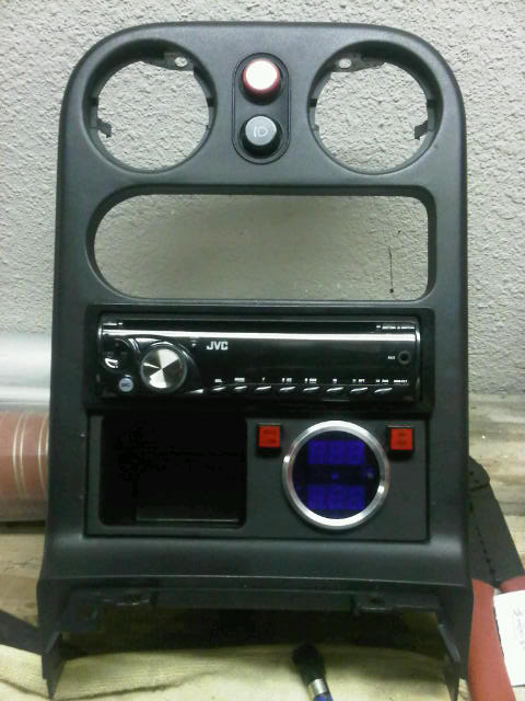
Looking good. The cubby with single gauge position came from Moss Motors. Unfortunately, it is setup to put the gauge in the least visible position. I'll have to see if it's tolerable. OTW, more fabrication will be in order.
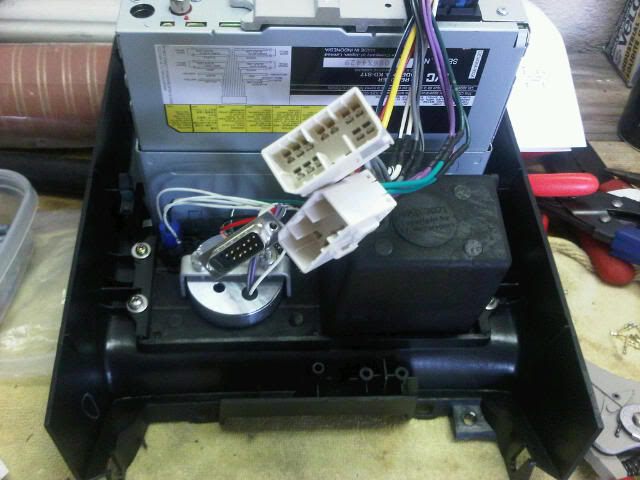
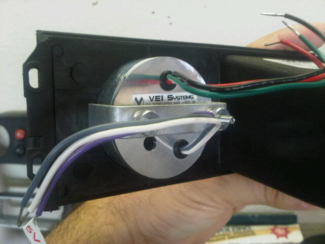
Shot from the back. All wires terminated into connectors for installation/removal.
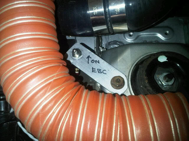
Added an EBC disable switch in the engine compartment. This is for two reasons: (1) I'll be able to manually disable EBC if my manual WI test shows that I have a clogged nozzle; and (2) I'll be able to manually disable EBC when my teenage daughter wants to borrow the car. How long before my teenage daughter finds the "magic" switch that changes the car from a 5psi turbo to a 10psi turbo? I wonder.
I purchased a VEI combined vacuum/boost and AFR gauge. I wanted those two parameters full time, but I wanted to keep from ricing the car too much. This gauge fit the bill.
Compact, rugged (billet aluminum) and made in the USA. What could be better?
Installed with low water light and combination WI Test Switch and WI Pressure Light. See my schematics for how these work. Note that I was not able to use an OEM cluster light for low water. The 90 models did not have the OEM light.
LC-1 combination calibration switch and status LED. The labels for all these switches were made from clear mailing labels with 9 point Arial type. The switch caps pop off for convenient labeling. These types of switches are available from Digikey or Mouser.
Looking good. The cubby with single gauge position came from Moss Motors. Unfortunately, it is setup to put the gauge in the least visible position. I'll have to see if it's tolerable. OTW, more fabrication will be in order.
Shot from the back. All wires terminated into connectors for installation/removal.
Added an EBC disable switch in the engine compartment. This is for two reasons: (1) I'll be able to manually disable EBC if my manual WI test shows that I have a clogged nozzle; and (2) I'll be able to manually disable EBC when my teenage daughter wants to borrow the car. How long before my teenage daughter finds the "magic" switch that changes the car from a 5psi turbo to a 10psi turbo? I wonder.
Reply
0
0
Thread Starter
Elite Member
iTrader: (4)
Joined: Mar 2008
Posts: 6,301
Total Cats: 697
From: Granbury, TX
So, given the complexity of my WI control systems and failsafes, I wanted to be able to check all systems to confirm functionality before first start. My initial checklist basically went as follows:
1. Setup MSPNP and VEI for LC-1.
2. Setup MSPNP for Spark Table Switching.
3. Setup MSPNP for Water Injection.
4. Perform LC-1 Free Air Calibration procedure.
5. Prior to filling washer tank with distilled water, test Low Fluid Lamp and cutout of WI Pump using WI Test Switch.
6. Fill washer tank with distilled water.
7. Look for tank leaks.
8. Confirm Low Fluid Lamp extinguished.
9. Test WI Pump with WI Test Switch. Confirm illumination of WI Pressure LED. WI Pressure LED should remain illuminated for a short period of time while WI pressure bleeds off.
One of the reasons for being so detailed is that Murphy's law is supposed to strike those that are unprepared. Alas, Murphy never cuts slack. My scorecard:
1. OK for MSPNP. VEI gauge had a software issue that prevented calibration. VEI is sending a new one out no charge.
2-3. OK.
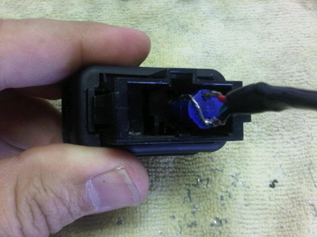
4. Had cold solder joint on LC-1 calibration switch. This took a little bit of cussing to figure out.
5. OK. Whew.
6-8. OK.
9. The pump would engergize but the WI Pressure LED would not illuminate. WTF? Start tearing things apart. Sure enough -- water going to pump -- no water at nozzle. Hmmmm. It turns out that the checkvalve was stuck (sitting on the shelf too long I guess). A shot of compressed air fixed that -- but not before most cusswords in the English language (mostly of French origin) had been uttered/yelled. In the end, this was a pass and my leakdown test took a repeatable 0.5 seconds.
So, component reliability thus far so-so. Design of failsafes and operation of indications so I can tell WTF is going on -- AWESOME.
Screw it -- let's start the car.
1. Setup MSPNP and VEI for LC-1.
2. Setup MSPNP for Spark Table Switching.
3. Setup MSPNP for Water Injection.
4. Perform LC-1 Free Air Calibration procedure.
5. Prior to filling washer tank with distilled water, test Low Fluid Lamp and cutout of WI Pump using WI Test Switch.
6. Fill washer tank with distilled water.
7. Look for tank leaks.
8. Confirm Low Fluid Lamp extinguished.
9. Test WI Pump with WI Test Switch. Confirm illumination of WI Pressure LED. WI Pressure LED should remain illuminated for a short period of time while WI pressure bleeds off.
One of the reasons for being so detailed is that Murphy's law is supposed to strike those that are unprepared. Alas, Murphy never cuts slack. My scorecard:
1. OK for MSPNP. VEI gauge had a software issue that prevented calibration. VEI is sending a new one out no charge.
2-3. OK.
4. Had cold solder joint on LC-1 calibration switch. This took a little bit of cussing to figure out.
5. OK. Whew.
6-8. OK.
9. The pump would engergize but the WI Pressure LED would not illuminate. WTF? Start tearing things apart. Sure enough -- water going to pump -- no water at nozzle. Hmmmm. It turns out that the checkvalve was stuck (sitting on the shelf too long I guess). A shot of compressed air fixed that -- but not before most cusswords in the English language (mostly of French origin) had been uttered/yelled. In the end, this was a pass and my leakdown test took a repeatable 0.5 seconds.
So, component reliability thus far so-so. Design of failsafes and operation of indications so I can tell WTF is going on -- AWESOME.
Screw it -- let's start the car.
Reply
0
0


