Building a blonde young beefcake wearing nothing but skimpy shorts named Rocky
 07-02-2014, 05:24 PM
#1201

It's the difference between collectively and all at once. Collectively on a track I might spend 10 seconds at full load, 1 second here, 4 seconds here, a few seconds here... But never will I go from 30 to 150 full load all at once then do it again over and over. Also, in regards to length of these pulls - I wish my 30-150mph pulls only took 6 seconds, but in reality these are much longer pulls and much more frequent than 1 minute per hour. I am very hard on the car.
Let's compare my internals to a delicious marshmallow... I can collectively cook my marshmallow in an open flame for 60 seconds, not all at once, a few seconds at a time will probably net me a decent looking treat after 60 seconds of total direct flame exposure. But if I toss that guy in open flame for 60 seconds straight I end up with two very different types of smore. Follow me?
Props to this random clip art site for helping me add a spot on visual representation of the marshmallow story.

Reply
 2
2

2
07-02-2014, 05:31 PM
#1202
Elite Member
iTrader: (37)

Join Date: Apr 2010
Location: Very NorCal
Posts: 10,441
Total Cats: 1,899
What exactly do you plan on doing to prep the block and head for new MLS head gasket while its all still in the car? I started looking back at all the head gaskets I've done and realized I've never dealt with an MLS before. I guess that's what I get for owning old cars 
Reply
0
0
07-02-2014, 06:01 PM
#1203
Luckily with MLS gaskets you don't end up with that stubborn gasket material that is baked to your mating surfaces. In fact, depending on the manufacturer you can get away with simply wiping the surface down with brake cleaner. Other manufacturers like to use a coating on their outer most layers of their MLS gasket that ends up partially sticking to the deck. This can be cleaned up with a light scuff pad and brake cleaner. You really want to avoid anything that visually changes the surface of the deck.
Don't use this:
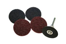
Or even though it's sometimes called a "gasket removal" bit, don't use this on aluminum.

After it's cleaned I take a straight edge and a set of feeler gauges to check flatness. On a car using an MLS gasket the tolerance is usually 0.004". Anything outside of that it needs to go in for deck surfacing. Obviously your cylinder head is more likely to warp given the differences in materials.
Don't use this:
Or even though it's sometimes called a "gasket removal" bit, don't use this on aluminum.
After it's cleaned I take a straight edge and a set of feeler gauges to check flatness. On a car using an MLS gasket the tolerance is usually 0.004". Anything outside of that it needs to go in for deck surfacing. Obviously your cylinder head is more likely to warp given the differences in materials.
Reply
1
1

 07-08-2014, 01:41 PM
#1206
This past Sunday I was able to get back out to the garage for a bit. A few small action items were crossed off the list.
AN line routing was actually way easier than I had anticipated. In the wheel well of the NB you have a plastic cover on the front/inner side, when you remove that you have access to the area on the bottom side of the trunk just in front of where a roll bar mounts. I used a hole saw and punched out a circle on each side allowing the supply and feed lines to route comfortably under the car. Then using a more robust version of a conduit mount I fixed the lines near the frame rails, one on the passenger side, one on the drivers.
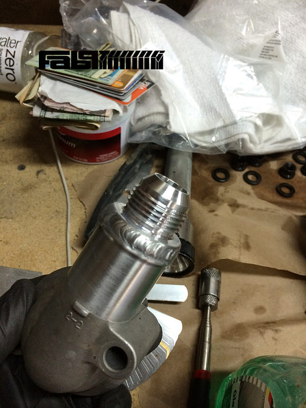
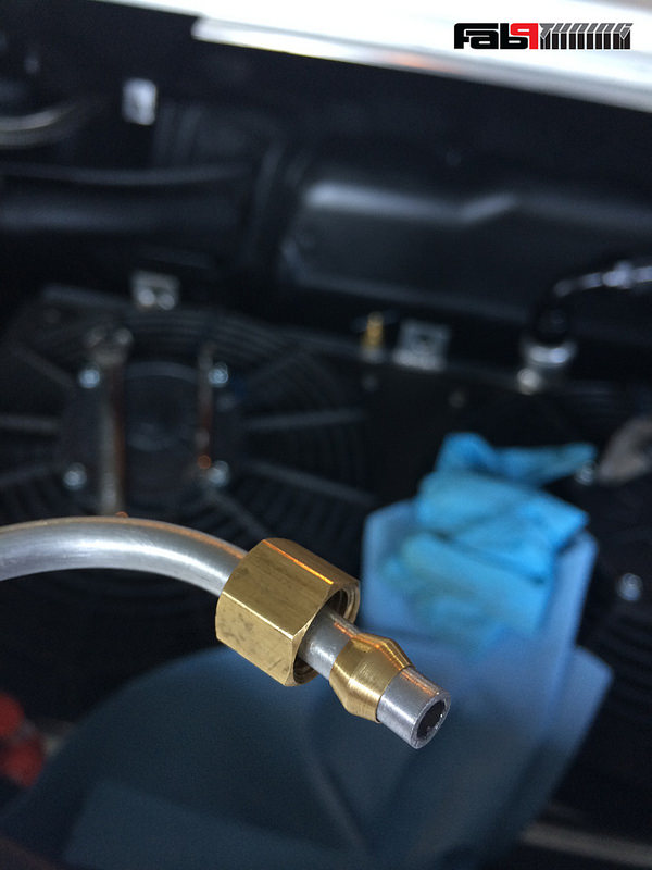
The next step was to prepare the coolant necks on the engine... Simple stuff here.
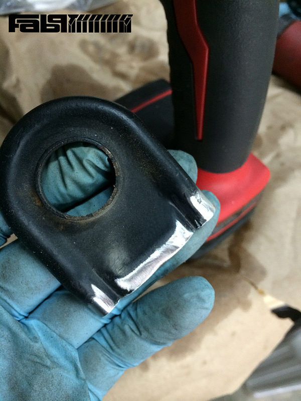
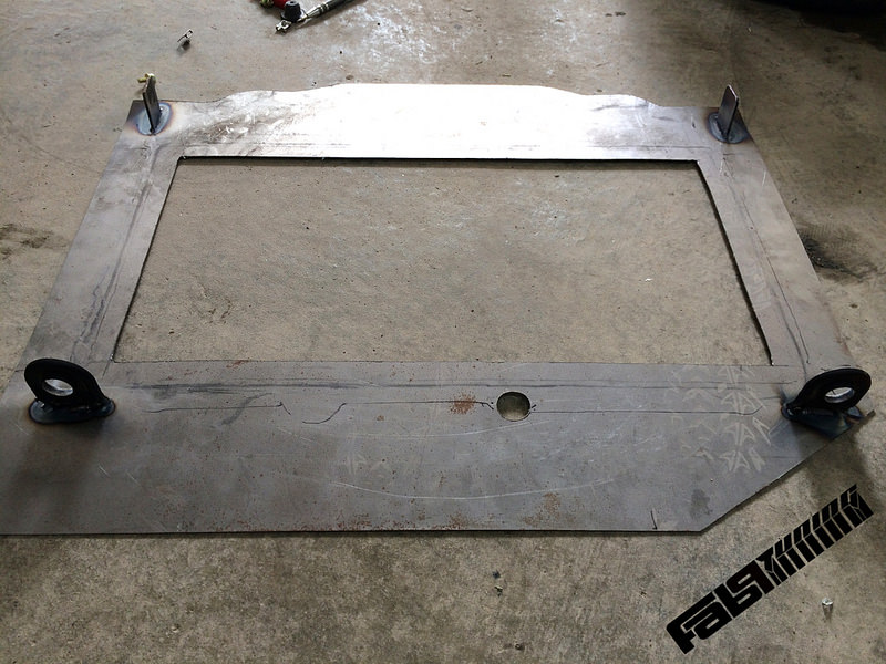
Now for mounting the Koyo to the shroud.. I wanted to leave the Koyo as un-molested as possible to keep things serviceable down the road. So for this I took my factory upper mounts and cut them down to weld them to the shroud. This would allow me to easily slide the radiator in and out of place using the rubber isolators. I chopped them down and cleaned them off for welding.
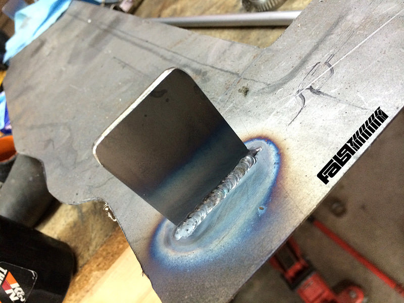
This would cover the bottom/top who knows the orientation at this point.. For the other end I decided to use hardware, so I welded these two tabs on that will be drilled to line up with existing 10mm threaded holes on the rad.
Here is what I ended up with, it now only takes a 10mm wrench and a minute or so to remove the radiator.
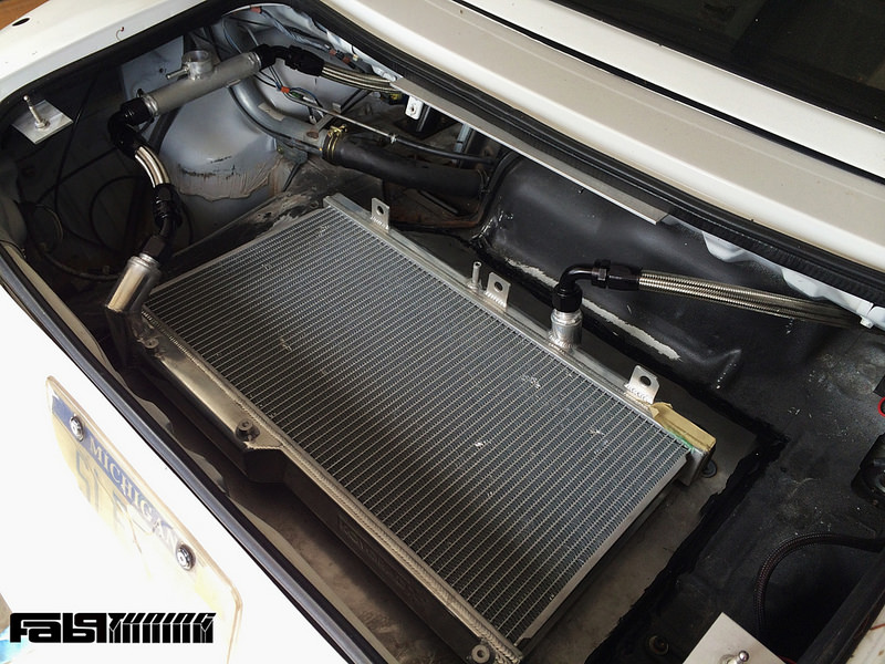
Mocked up, everything was looking pretty good. I used rivets and 3M Window weld to mount the panel in place and make sure it was air tight. Once the 3M urethane cured up the assembly was really solid.
Next steps are to remove the radiator and prep the back for paint, then work on a fan shroud and wiring up some relays for fans.
- Route AN lines
- Weld AN fittings to coolant necks
- Fabricate a mounting system for the Koyo
- Mount the shroud to the trunk
AN line routing was actually way easier than I had anticipated. In the wheel well of the NB you have a plastic cover on the front/inner side, when you remove that you have access to the area on the bottom side of the trunk just in front of where a roll bar mounts. I used a hole saw and punched out a circle on each side allowing the supply and feed lines to route comfortably under the car. Then using a more robust version of a conduit mount I fixed the lines near the frame rails, one on the passenger side, one on the drivers.
The next step was to prepare the coolant necks on the engine... Simple stuff here.
Now for mounting the Koyo to the shroud.. I wanted to leave the Koyo as un-molested as possible to keep things serviceable down the road. So for this I took my factory upper mounts and cut them down to weld them to the shroud. This would allow me to easily slide the radiator in and out of place using the rubber isolators. I chopped them down and cleaned them off for welding.
This would cover the bottom/top who knows the orientation at this point.. For the other end I decided to use hardware, so I welded these two tabs on that will be drilled to line up with existing 10mm threaded holes on the rad.
Here is what I ended up with, it now only takes a 10mm wrench and a minute or so to remove the radiator.
Mocked up, everything was looking pretty good. I used rivets and 3M Window weld to mount the panel in place and make sure it was air tight. Once the 3M urethane cured up the assembly was really solid.
Next steps are to remove the radiator and prep the back for paint, then work on a fan shroud and wiring up some relays for fans.
Reply
3
3
07-14-2014, 09:59 AM
#1209
More Sunday-funday updates.
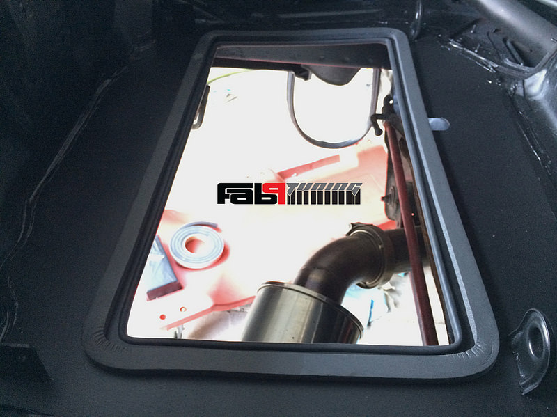
Everything is mounted in and functional so I went back and did some finish work on the trunk.
Weather seal around the opening:
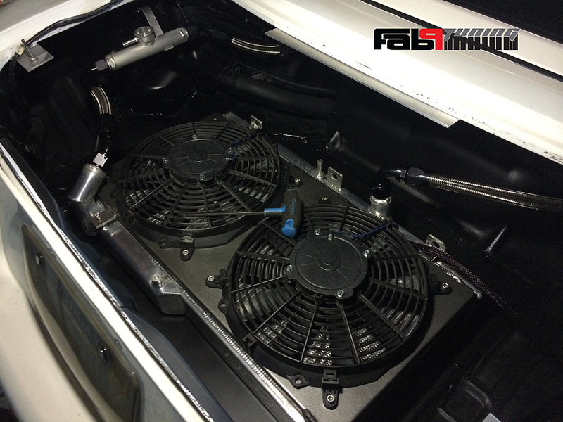
I chopped up my old fan shroud and welded on new tabs for the Koyo radiator, then I mounted the two fans:
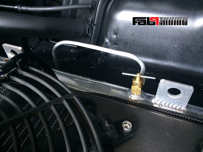
I will be adding a couple of bleeders to the system and I had a hole to plug here so it seemed like a great place to start. It also helps tremendously when trying to fill the system:
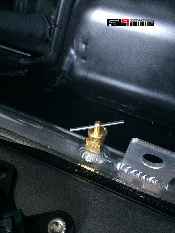
I needed to route it out of the trunk (onto the ground where I'd place a drain pan). So I went with aluminum tubing and a small opening in the trunk.
Everything is mounted in and functional so I went back and did some finish work on the trunk.
Weather seal around the opening:
I chopped up my old fan shroud and welded on new tabs for the Koyo radiator, then I mounted the two fans:
I will be adding a couple of bleeders to the system and I had a hole to plug here so it seemed like a great place to start. It also helps tremendously when trying to fill the system:
I needed to route it out of the trunk (onto the ground where I'd place a drain pan). So I went with aluminum tubing and a small opening in the trunk.
Reply
1
1
 07-14-2014, 10:44 AM
#1214
Correct - Fans are pullers, the area above the trunk is low pressure and heat will naturally want to raise - no reason to fight nature.
Also correct on the "scoop". At some point ducting will be built into a diffuser. Also the exhaust will be routed differently. Although I think for this season it will work just fine. If not I'll make changes.
Also correct on the "scoop". At some point ducting will be built into a diffuser. Also the exhaust will be routed differently. Although I think for this season it will work just fine. If not I'll make changes.
Reply
1
1
 07-15-2014, 10:51 AM
#1216
The aero engineer I'm working with seems to be confident this will work quite well but I've never seen it done on a Miata so who knows.
Reply
1
1
07-15-2014, 11:13 AM
#1217
Moderator


iTrader: (12)
Join Date: Nov 2008
Location: Tampa, Florida
Posts: 20,664
Total Cats: 3,013
Hose length makes a big difference in the effort required to move fluid. Often, if it is a longer distance, a larger diameter will be used for the run and then necked down to the requisite size on each end. 
Reply
0
0
07-15-2014, 11:15 AM
#1218

But now that you mention it. Using an inline water pump to assist flow on this thing could probably be a mega help to cooling capacity. Ron Davis here you come.
Reply
0
0
07-15-2014, 11:32 AM
#1219
If you set up a scoop/diffuser and then duct the back of the rad to the trunk, there's potential to create some serious downforce in addition to cooling, isn't it? In addition to the already beneficial weight over the rear wheels.
So this might be even more beneficial to your spin happy monster.
So this might be even more beneficial to your spin happy monster.
Reply
0
0
07-15-2014, 11:43 AM
#1220
Right, it will help the situation but it's not the proper way to produce downforce. The Drag to downforce ratio created by this setup is not optimal. Where as a typical wing will produce more downforce and less drag because it's easier for the air flow to roll off the back of a wing as opposed to changing it's direction and pushing it through a radiator/deck lid.
As for the flow of fluid, you're both correct. The line size is important and I'll likely end up with an electrical pump regardless.
As for the flow of fluid, you're both correct. The line size is important and I'll likely end up with an electrical pump regardless.
Last edited by FAB; 07-15-2014 at 12:01 PM.
Reply
1
1


