Hornetball's Build

 03-03-2011, 10:26 AM
#23
Elite Member
Thread Starter
iTrader: (4)

Join Date: Mar 2008
Location: Granbury, TX
Posts: 6,301
Total Cats: 696
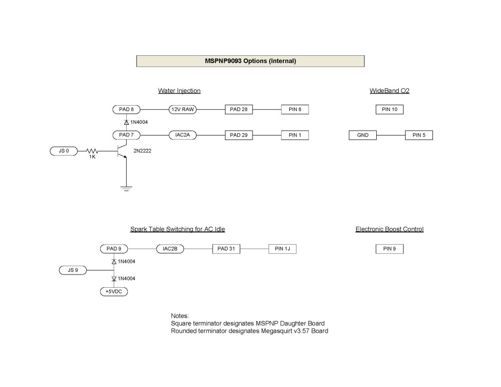
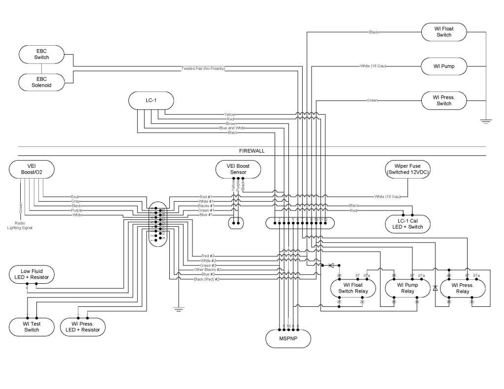
FYI, these are the MSPNP mods that were done and my scheme for a WI failsafe (thanks to all that made comments):


Got some parts in, so I'm hoping to make a lot of progress this coming weekend. In the meantime, I'm really sucking it up on my drive to work:
Torque . . .
Got some parts in, so I'm hoping to make a lot of progress this coming weekend. In the meantime, I'm really sucking it up on my drive to work:
Torque . . .

Reply
 0
0

0
03-06-2011, 07:24 PM
#24
Elite Member
Thread Starter
iTrader: (4)
Join Date: Mar 2008
Location: Granbury, TX
Posts: 6,301
Total Cats: 696
OK, made some progress this weekend!
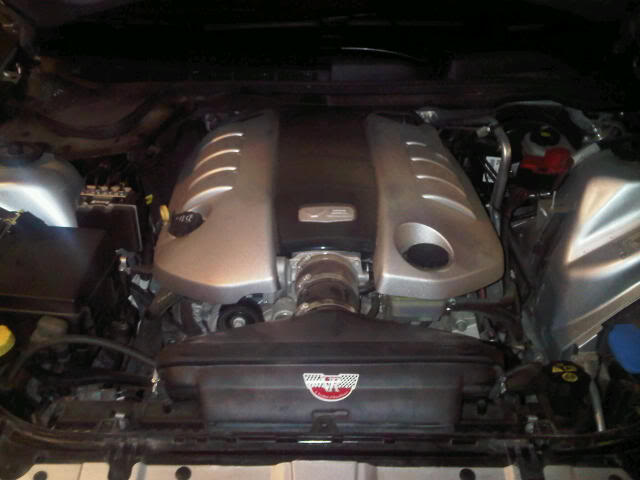
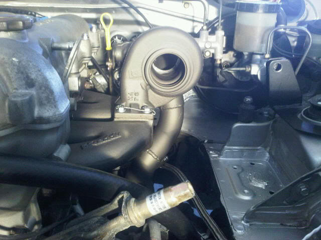
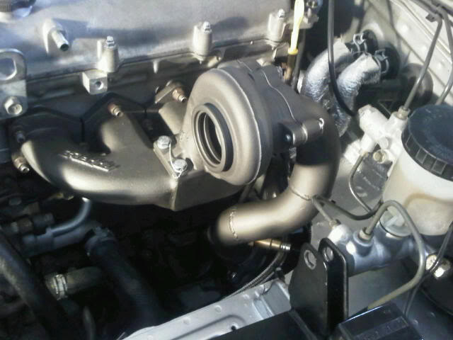
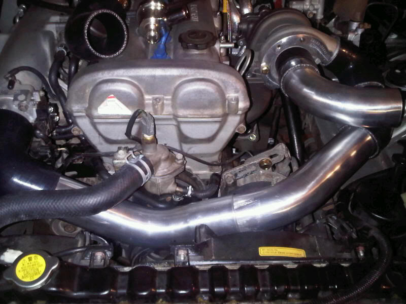
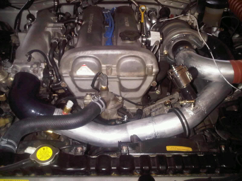
Started out by loosely fitting some parts to see what needs to change/what I need to order/what I need to fab. As I get deeper into this, it looks like I'm using less and less of the Greddy stuff. I guess that's typical. Here's a pic of the mockup:
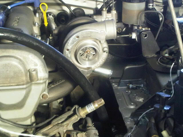
It's cool to finally see a turbo on the car, even if it's only for a few minutes. The Greddy oil drain fitting is angled at the optmum angle to cause structure to cut the drain line in half. Maybe this works if you're routing all the way to the other side of the engine, but I have my doubts. For a drilled oil pan, this is a no-go. New drain fitting on order. Also, from the picture, the power steering belt tensioner will have to go. I need that space. Hmmmm . . . maybe its time to depower.
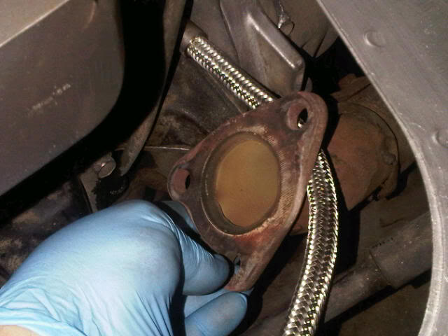
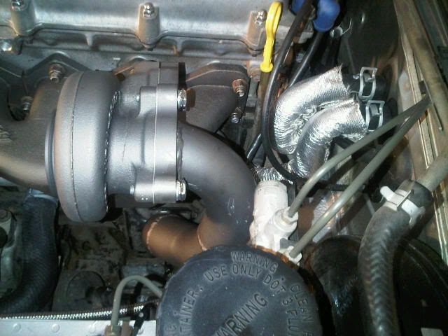
What is it with Greddy and oil lines?? This shows how the pressure line with straight fittings points directly at the exhaust pipe. I guess they want your car to burn to the ground so that they can sell you another kit on your next car. Reckless engineering. I'll need to locate a line with a 45� or 90� fitting so I can route high-pressure oil AWAY from the exhaust pipe.
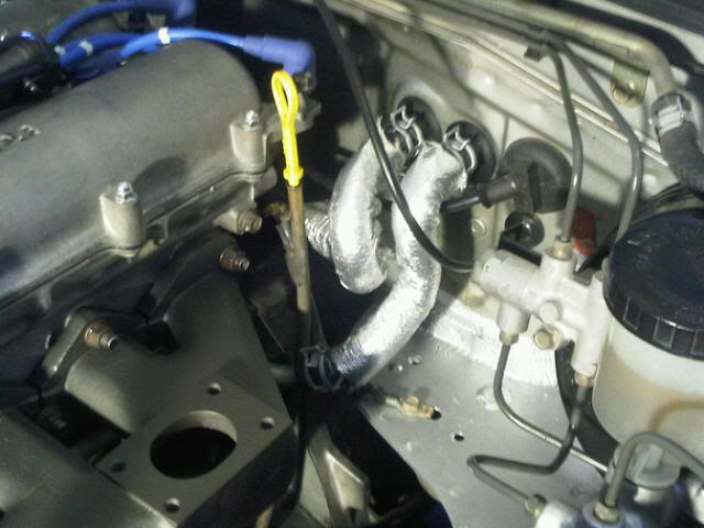
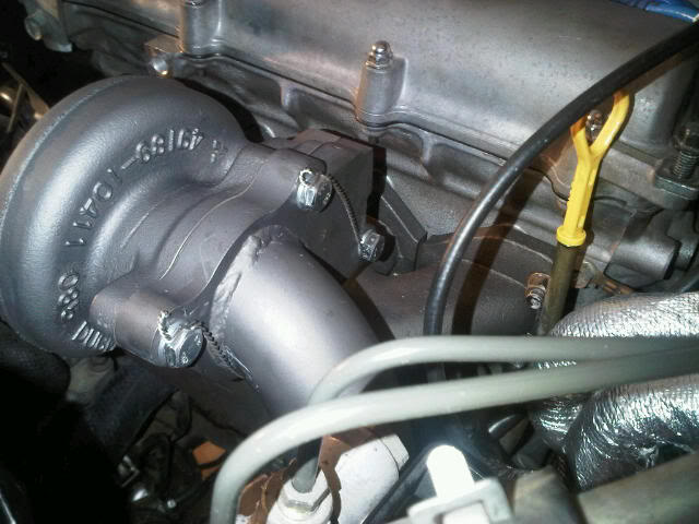
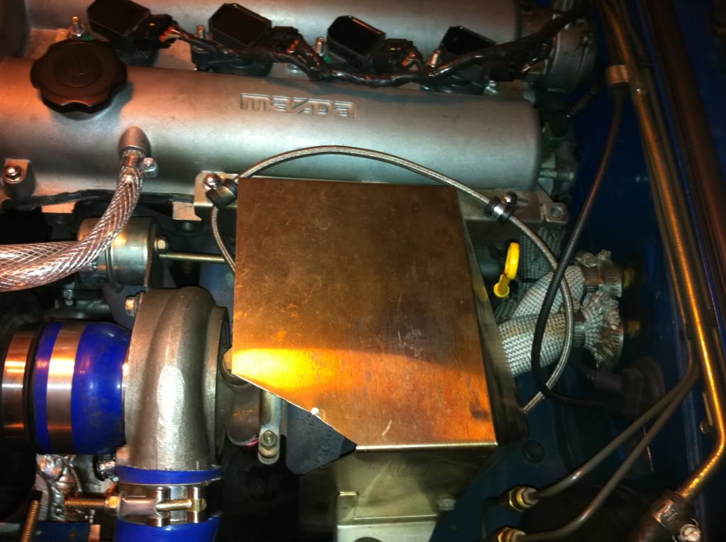
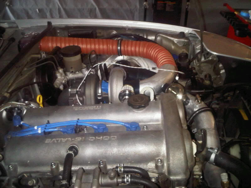
Exhaust manifold mounted and torqued. This picture also shows the shielding sleeves on the heater hoses. I bent the heater return hard line back a bit for extra clearance. The sleeves were tricky to get on to the molded hoses. I ended up inserting some rebar into the hoses to straighten them. That allowed me to slide the sleeves on. It was a snug fit, but it turned out pretty well.
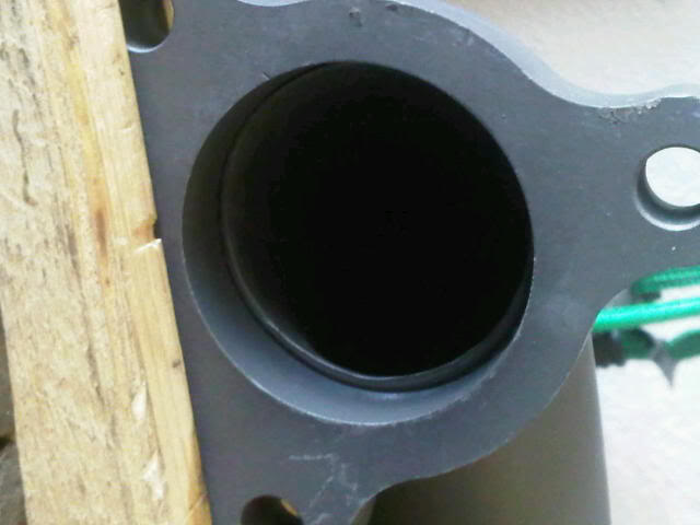
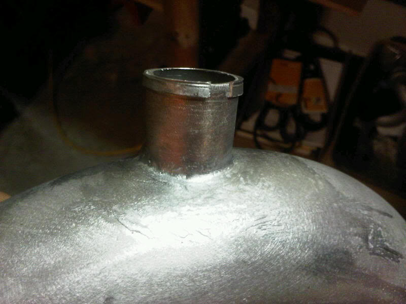
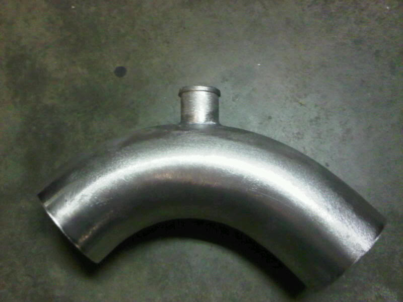
The Greddy downpipe is not known for flowing well, but this is ridiculous. That sharp lip leading into the downward bend is going to cause severe flow separation.
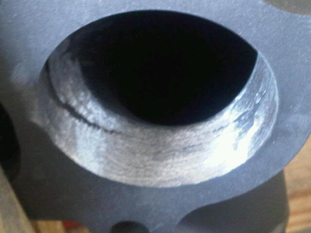
That's better.
The rest of the exhaust install was uneventful. I'm pretty happy with how it all fit. Also, got a chance to do some safety wiring. That's my form of relaxation . . . I'm a sick puppy. Pics:
Started out by loosely fitting some parts to see what needs to change/what I need to order/what I need to fab. As I get deeper into this, it looks like I'm using less and less of the Greddy stuff. I guess that's typical. Here's a pic of the mockup:
It's cool to finally see a turbo on the car, even if it's only for a few minutes. The Greddy oil drain fitting is angled at the optmum angle to cause structure to cut the drain line in half. Maybe this works if you're routing all the way to the other side of the engine, but I have my doubts. For a drilled oil pan, this is a no-go. New drain fitting on order. Also, from the picture, the power steering belt tensioner will have to go. I need that space. Hmmmm . . . maybe its time to depower.
What is it with Greddy and oil lines?? This shows how the pressure line with straight fittings points directly at the exhaust pipe. I guess they want your car to burn to the ground so that they can sell you another kit on your next car. Reckless engineering. I'll need to locate a line with a 45� or 90� fitting so I can route high-pressure oil AWAY from the exhaust pipe.
Exhaust manifold mounted and torqued. This picture also shows the shielding sleeves on the heater hoses. I bent the heater return hard line back a bit for extra clearance. The sleeves were tricky to get on to the molded hoses. I ended up inserting some rebar into the hoses to straighten them. That allowed me to slide the sleeves on. It was a snug fit, but it turned out pretty well.
The Greddy downpipe is not known for flowing well, but this is ridiculous. That sharp lip leading into the downward bend is going to cause severe flow separation.
That's better.
The rest of the exhaust install was uneventful. I'm pretty happy with how it all fit. Also, got a chance to do some safety wiring. That's my form of relaxation . . . I'm a sick puppy. Pics:
Reply
0
0
03-06-2011, 08:31 PM
#25
Cpt. Slow

iTrader: (25)
Join Date: Oct 2005
Location: Oregon City, OR
Posts: 14,189
Total Cats: 1,135
What material are those bolts made out of?
Also, doesn't the downpipe hold the rest of the exhaust much higher, letting you run the oil feed line below it? Mine does, although it's an aftermarket 2.5".
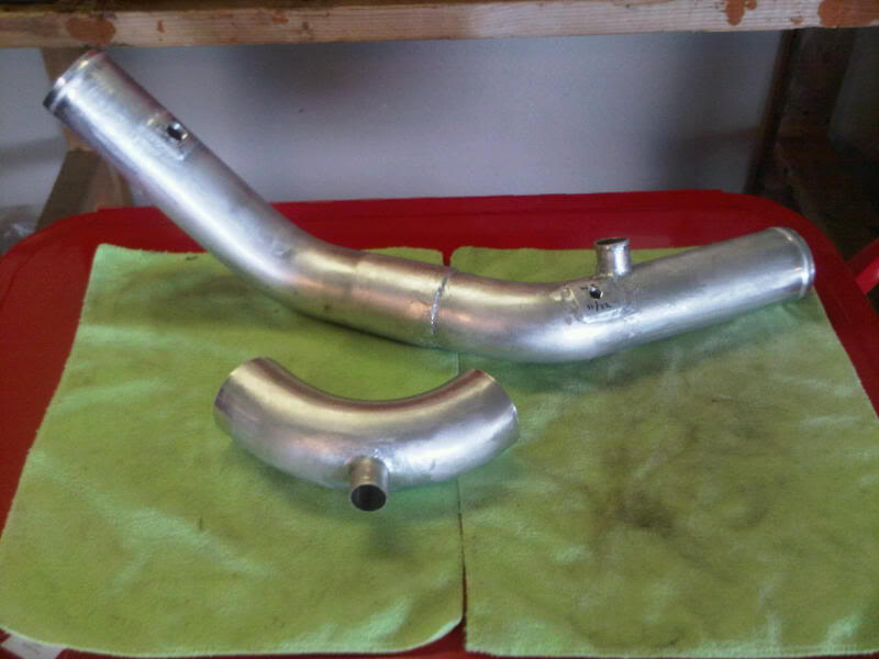
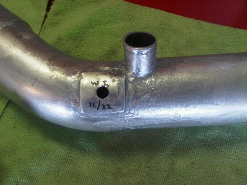
For the return, you can modify the existing unit two ways, neither of which I've tried:
1. Cut off and weld a straight piece of pipe on
2. Cut off and drill and tap for a -AN-NPT fitting
It might be a little thin for option #2, but you could solve this by welding a thick NPT bung on there.
Also, doesn't the downpipe hold the rest of the exhaust much higher, letting you run the oil feed line below it? Mine does, although it's an aftermarket 2.5".
For the return, you can modify the existing unit two ways, neither of which I've tried:
1. Cut off and weld a straight piece of pipe on
2. Cut off and drill and tap for a -AN-NPT fitting
It might be a little thin for option #2, but you could solve this by welding a thick NPT bung on there.
Reply
0
0
03-06-2011, 09:22 PM
#26
Elite Member
Thread Starter
iTrader: (4)
Join Date: Mar 2008
Location: Granbury, TX
Posts: 6,301
Total Cats: 696
What material are those bolts made out of?
Also, doesn't the downpipe hold the rest of the exhaust much higher, letting you run the oil feed line below it? Mine does, although it's an aftermarket 2.5".
For the return, you can modify the existing unit two ways, neither of which I've tried:
1. Cut off and weld a straight piece of pipe on
2. Cut off and drill and tap for a -AN-NPT fitting
It might be a little thin for option #2, but you could solve this by welding a thick NPT bung on there.
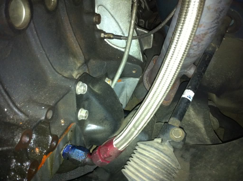
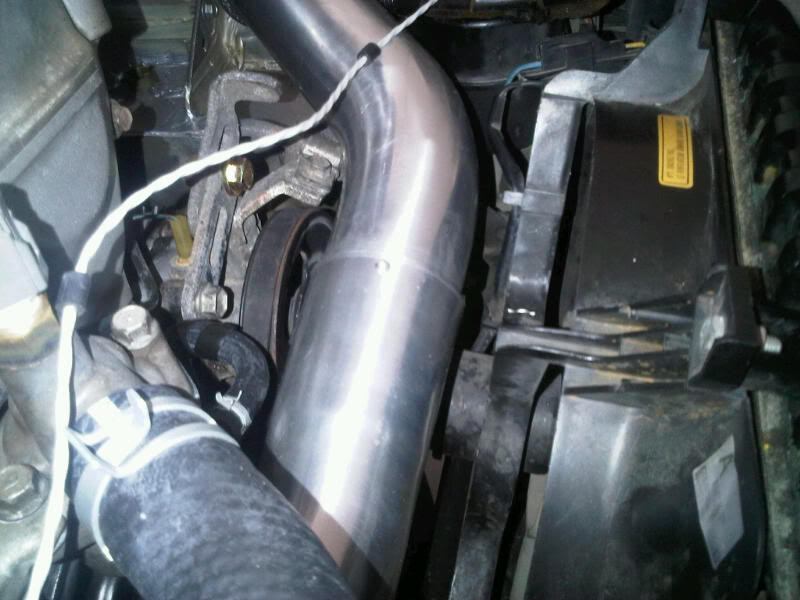
The Greddy downpipe preserves the stock exhaust location -- I even re-used the transmission bracket. However, I'll need to check on whether I can route below -- I haven't tried that. If I can secure with an Adel clamp and get some clearance, that would be great.
I found a straight return fitting online. Hopefully, that will do the trick.
Thanks Curly!
Reply
0
0
 03-06-2011, 10:42 PM
#28
Elite Member
Thread Starter
iTrader: (4)
Join Date: Mar 2008
Location: Granbury, TX
Posts: 6,301
Total Cats: 696
http://www.summitracing.com/search/P...?Ns=Rank%7cAsc
Curly, no luck on routing the pressure hose below the exhaust pipe. If anyone has a suggested routing for the Greddy pressure hose, I'd love to see a picture.
Reply
0
0
03-06-2011, 11:11 PM
#29
Cpt. Slow
iTrader: (25)
Join Date: Oct 2005
Location: Oregon City, OR
Posts: 14,189
Total Cats: 1,135
Huh, mine's apparently routed above the exhaust as well, who knew.
This actually brought to my attention an unfinished part of my build, as it needs to be secured more.
If you can't tell, it's routed above the exhaust, along one of the heater core lines, over to the back of the valve cover, around the heat shield, then into the turbo.
At one point it was inside the heater core fire wrap, but it added a big hassle if I wanted to remove the oil feed or heater core line.
It was also routed along the brake lines to come in from the fender instead of the valve cover, but that added about a dozen little zip ties I had to cut every time I removed my engine. Not that that happens often.
Reply
0
0
03-07-2011, 12:14 PM
#30
Elite Member
Thread Starter
iTrader: (4)
Join Date: Mar 2008
Location: Granbury, TX
Posts: 6,301
Total Cats: 696
Thanks Curly. That helps -- although my downpipe geometry is a bit more challenging. Also, your line diameter looks smaller than mine. Are you using the stock Greddy line or have you fabbed an AN replacement?
Reply
0
0
03-07-2011, 07:58 PM
#32
Elite Member
iTrader: (2)

Join Date: Jan 2007
Location: Los Angeles, CA
Posts: 8,682
Total Cats: 130
I just saw this.
This is similar to the Aquamist DDS3 junction box. Differences are the DDS3 triggers a trim map change and also has flow sensor input.
See here:
http://forums.nasioc.com/forums/show....php?t=1151715
Reply
0
0
 .
03-21-2011, 07:02 PM
.
03-21-2011, 07:02 PM
#34
Elite Member
Thread Starter
iTrader: (4)
Join Date: Mar 2008
Location: Granbury, TX
Posts: 6,301
Total Cats: 696
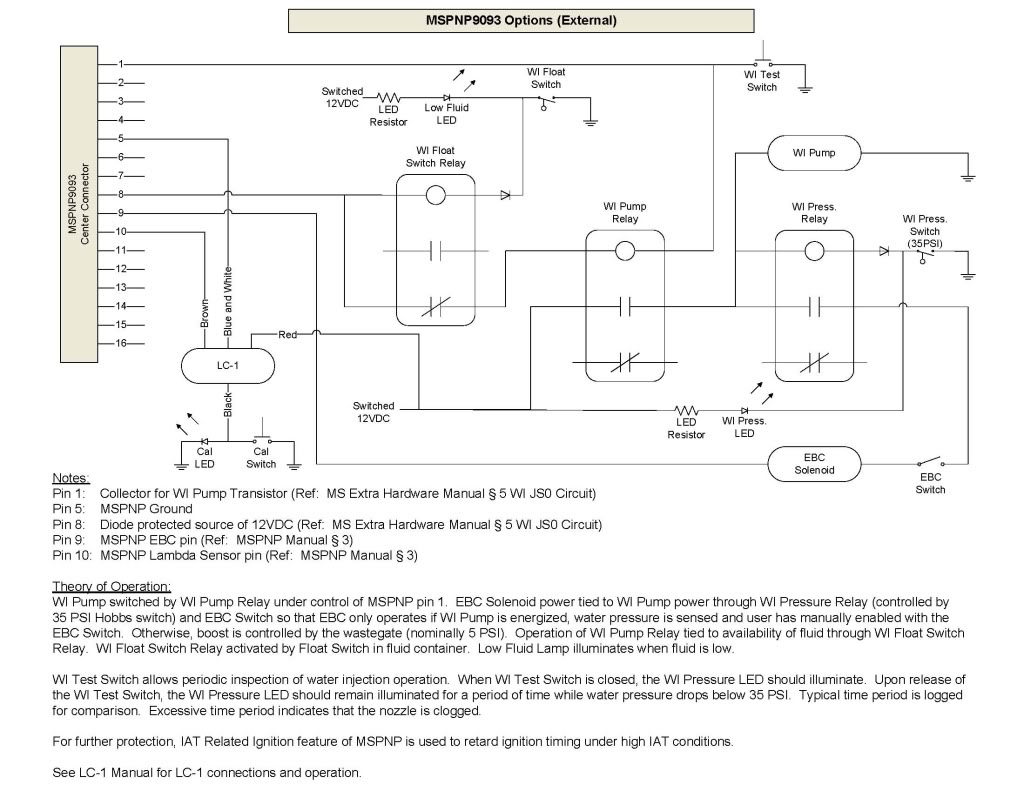
Added LC-1 wiring and a WI Pressure Relay and Indication LED. This will allow me to observe bleed-down rates when I press the WI Test Switch to test for nozzle clogging. Revised schematics:
Last edited by hornetball; 04-05-2011 at 12:08 PM.
Reply
0
0
03-21-2011, 07:25 PM
#35
Elite Member
Thread Starter
iTrader: (4)
Join Date: Mar 2008
Location: Granbury, TX
Posts: 6,301
Total Cats: 696
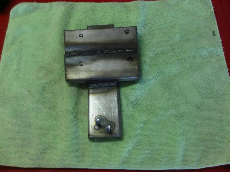
I used my new (reconditioned -- on sale) MIG welder to fabricate this bracket from 1/8" C-channel. Mounting holes were tapped for #8 machine screws (1/8" is plenty thick for threads). Bolts were welded on the bottom to match the original evap cannister bracket bolts and re-use existing holes in the car:
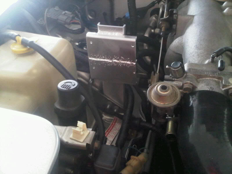
Here's the finished bracket. Trimmed, painted and mounted:
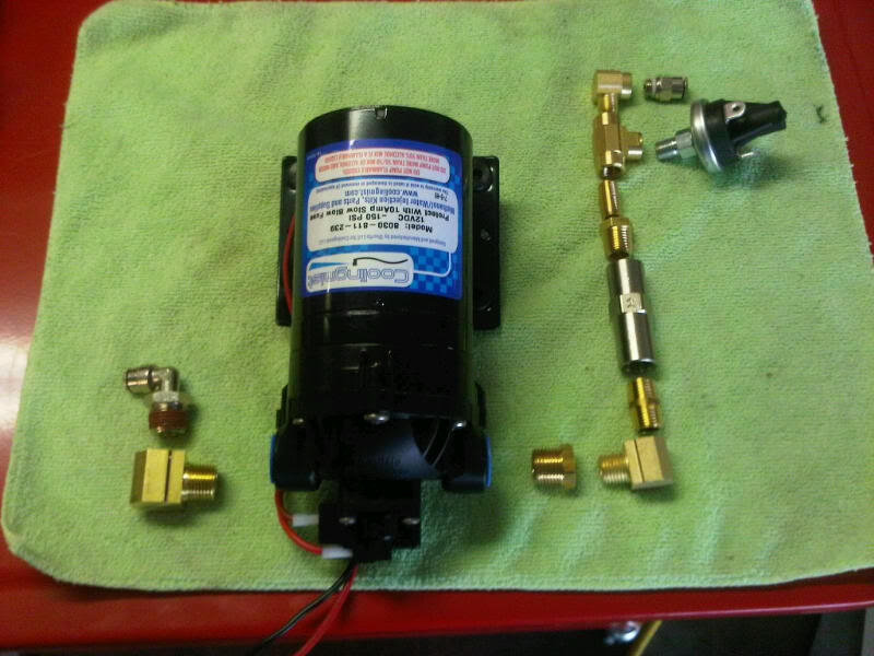
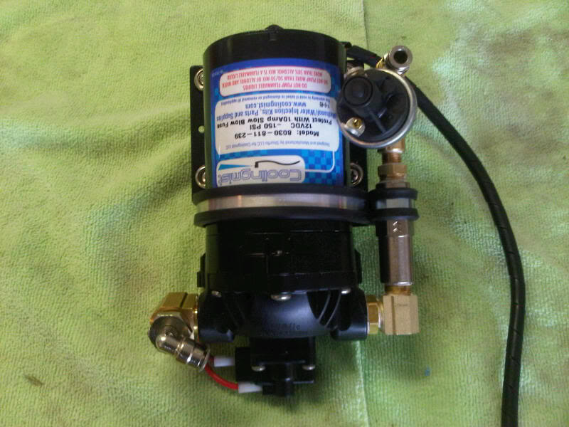
Packaging is everything on a Miata. This picture shows the pump along with check valve/filter and 35 PSI pressure switch.
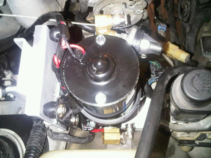
Here's the same thing fully assembled. Adel clamps (3" and 3/4") are used to further secure the large stack of components. Mil-spec Adel clamps up to 4" are available (and pretty reasonable) from Aircraft Spruce.
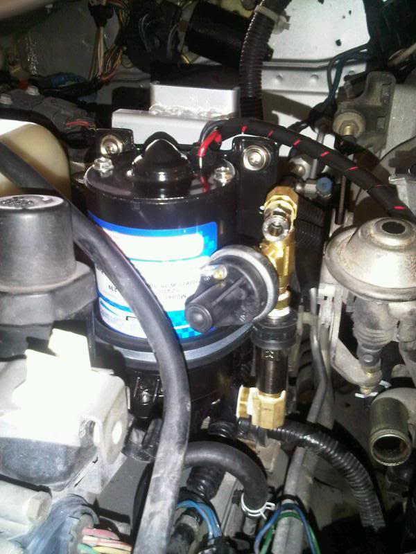
Here are pictures of the assembly mounted in the car. Pretty happy with how this turned out -- secure with good clearance all around.
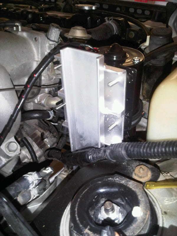
Here's the finished bracket. Trimmed, painted and mounted:
Packaging is everything on a Miata. This picture shows the pump along with check valve/filter and 35 PSI pressure switch.
Here's the same thing fully assembled. Adel clamps (3" and 3/4") are used to further secure the large stack of components. Mil-spec Adel clamps up to 4" are available (and pretty reasonable) from Aircraft Spruce.
Here are pictures of the assembly mounted in the car. Pretty happy with how this turned out -- secure with good clearance all around.
Last edited by hornetball; 03-22-2011 at 08:43 AM.
Reply
0
0
03-21-2011, 07:36 PM
#37
Elite Member
iTrader: (2)
Join Date: Jan 2007
Location: Los Angeles, CA
Posts: 8,682
Total Cats: 130
By trim map change I meant-
The hydra has a 3D map that allows you to add or remove fuel and timing if signal is present (ground or hot) on one of the hydra's inputs. That hydra input is typically wired to your failsafes (flow sensor, float sensor). That way if you have no flow or are out of water, your 3D maps turn off and you do not blow up your motor.
The hydra has a 3D map that allows you to add or remove fuel and timing if signal is present (ground or hot) on one of the hydra's inputs. That hydra input is typically wired to your failsafes (flow sensor, float sensor). That way if you have no flow or are out of water, your 3D maps turn off and you do not blow up your motor.
Reply
0
0
03-21-2011, 09:01 PM
#38
Elite Member
Thread Starter
iTrader: (4)
Join Date: Mar 2008
Location: Granbury, TX
Posts: 6,301
Total Cats: 696
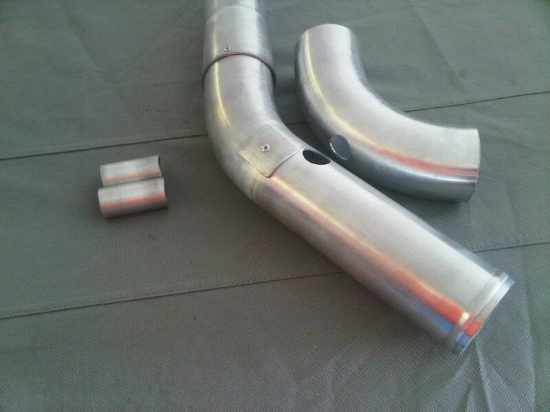
So, I'm planning to use WI with automatic failsafes instead of an intercooler. To support this, I'm constructing a simple, 2.5" aluminum intake that follows the stock routing relatively closely and supports my add-ons (IAT sensor, WI nozzle, BOV).
The main section from the turbo to the TB consists of two CXR 45� mandrel bends. Silicone consists of a 90� bending reducer followed by a 45� bend at the turbo outlet, and a 90� bend at the TB. The mandrel bends were trimmed and one side was expanded with a "single-use" HF exhaust pipe expander (which I will now return -- free tool rental). This gave me a slip joint for twisting, shifting, etc.
The section leading into the turbo is much simpler, a trimmed CXR 90� mandrel bend.
Here is a mockup picture:
Once I was happy with the angles on the main section, a single 1/8" rivet held everything together for attachment:
Here are the parts ready for heat with holes for the BOV ports, pipe thread doublers (patches cut from 2.5" tubing) and short 1" aluminum tubing lengths:
A long bolt with body washers holds the BOV tube for attachment:
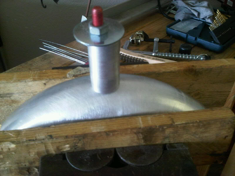
On the BOV tubes, a bead was fabricated by cutting off a ring of 1" tubing, slitting the ring and then placing over the neck for attachment:
Not too bad:
Here are the finished parts. You can see the doublers that were attached to the main tube for use as bungs for the IAT sensor, idle air port and WI nozzle:
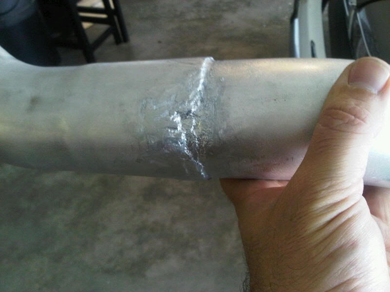
So, here's where I messed up . I wasn't too confident in my aluminum welding skills, so I used a process similar to brazing called HTS-2000. Inexpensive to do (only requires MAPP gas), and should theoretically give good results because there is a 500� difference between the melting points of HTS-2000 and aluminum. It is amazingly strong stuff, I've used it to repair the legs on outdoor furniture that has stood up to people that don't fit in the Miata. Unfortunately, on this larger project, I had some trouble with heat control and experienced a bit of carnage as a result. I wish I had just practiced up and used my welder. So, now I'll have to cover my sins with black paint. The intake is strong, lightweight and airtight, just not as pretty as I had hoped (won't be confused with Abe's work, for sure). Carnage pictures:
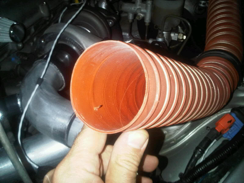
In the end, it worked out. Here's a final mockup with components test mounted. You can see how I've used SCAT duct to preserve my cowl induction. The air filter is a K&N RU-3780.
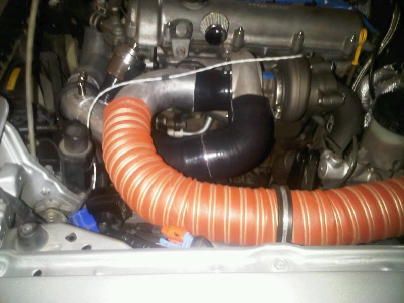
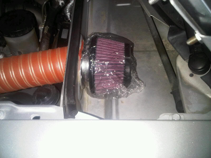
This photo shows the proper way to terminate SCAT tube. The internal wire is pulled out of the area that will clamp to the duct. It is cut and bent inward to form a stop. With the wire removed from the clamp area, you get an airtight seal and there is no chafing.
Now, where's my black paint . . . .
The main section from the turbo to the TB consists of two CXR 45� mandrel bends. Silicone consists of a 90� bending reducer followed by a 45� bend at the turbo outlet, and a 90� bend at the TB. The mandrel bends were trimmed and one side was expanded with a "single-use" HF exhaust pipe expander (which I will now return -- free tool rental). This gave me a slip joint for twisting, shifting, etc.
The section leading into the turbo is much simpler, a trimmed CXR 90� mandrel bend.
Here is a mockup picture:
Once I was happy with the angles on the main section, a single 1/8" rivet held everything together for attachment:
Here are the parts ready for heat with holes for the BOV ports, pipe thread doublers (patches cut from 2.5" tubing) and short 1" aluminum tubing lengths:
A long bolt with body washers holds the BOV tube for attachment:
On the BOV tubes, a bead was fabricated by cutting off a ring of 1" tubing, slitting the ring and then placing over the neck for attachment:
Not too bad:
Here are the finished parts. You can see the doublers that were attached to the main tube for use as bungs for the IAT sensor, idle air port and WI nozzle:
So, here's where I messed up
. I wasn't too confident in my aluminum welding skills, so I used a process similar to brazing called HTS-2000. Inexpensive to do (only requires MAPP gas), and should theoretically give good results because there is a 500� difference between the melting points of HTS-2000 and aluminum. It is amazingly strong stuff, I've used it to repair the legs on outdoor furniture that has stood up to people that don't fit in the Miata. Unfortunately, on this larger project, I had some trouble with heat control and experienced a bit of carnage as a result. I wish I had just practiced up and used my welder. So, now I'll have to cover my sins with black paint. The intake is strong, lightweight and airtight, just not as pretty as I had hoped (won't be confused with Abe's work, for sure). Carnage pictures:In the end, it worked out. Here's a final mockup with components test mounted. You can see how I've used SCAT duct to preserve my cowl induction. The air filter is a K&N RU-3780.
This photo shows the proper way to terminate SCAT tube. The internal wire is pulled out of the area that will clamp to the duct. It is cut and bent inward to form a stop. With the wire removed from the clamp area, you get an airtight seal and there is no chafing.
Now, where's my black paint . . . .
Last edited by hornetball; 03-22-2011 at 08:54 AM.
Reply
1
1


