
Low key red and tan build


Thread Starter
Junior Member
iTrader: (1)
Joined: Jul 2013
Posts: 64
Total Cats: 7
From: Jacksonville, FL
So the no intercooler idea is a pretty big fail for two reasons I should have expected.
1. It's difficult to keep boost below 6 psi.
2. IATs in this time of year are far worse than expect (~170 cruising in the afternoon)
I should have seen it coming, but all I saw was dollar signs. Moving on I ordered an intercooler from eBay seller dptmotorsport.
27"x5 5"X2 5" Aluminum Black Fmic Bar Plate Front Mount Turbo Intercooler | eBay
It was a shot in the dark. I didn't get a recommendation from anywhere, it literally was the cheapest example with the specs I wanted (2.5" in/out and black)
Also ordered a piping kit from cxmustang's eBay store.
2 5" inch DIY Aluminum 8pcs Turbo Intercooler Piping Pipe Kit Black Blk | eBay
This one wasn't the cheapest, but it was the cheapest one that looked like half way decent quality couplers and piping. Also black.
Plus I had to buy the following to make everything work:
-1.25" x 20" flex radiator hose
-2" to 2.5" 90 degree silicone reducing elbow to adapt to my 2" turbo outlet
-3/8" NPT bung for IAT sensor
-1" OD tube to weld on a bung for BOV
-.75" OD tube to weld on a bung for IACV
All totaled, DIY intercooler should be $206
The only problem is I sold my TIG welder to buy a new one and shipping is delayed. Install is delayed until next weekend.
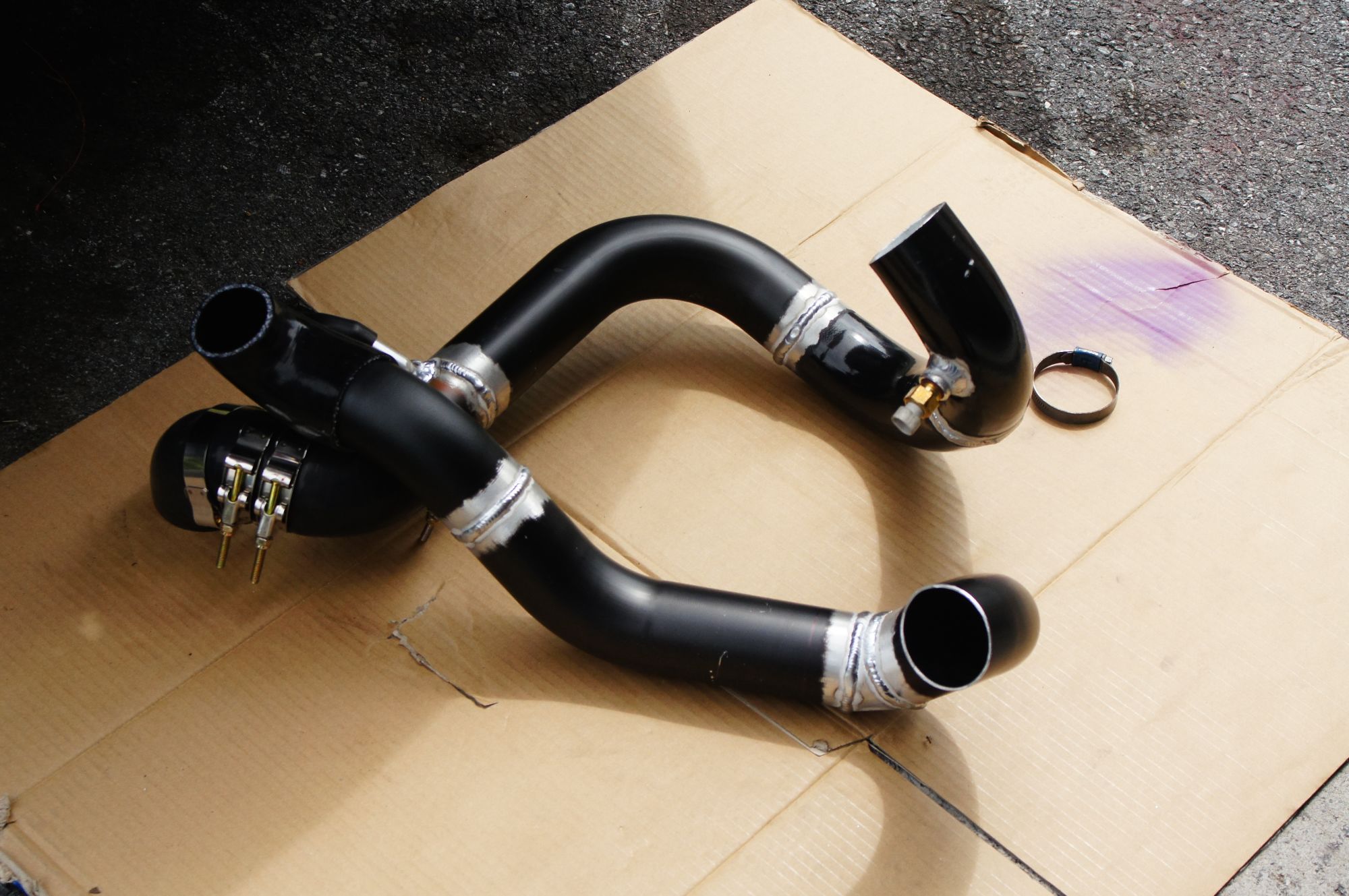
Pics of the intercooler and piping:
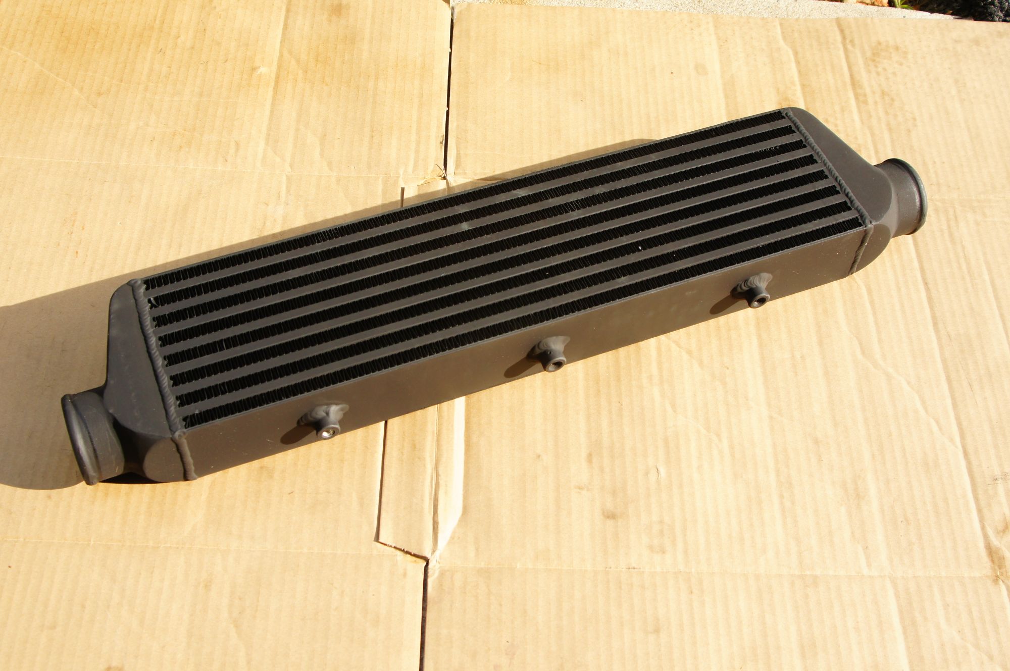
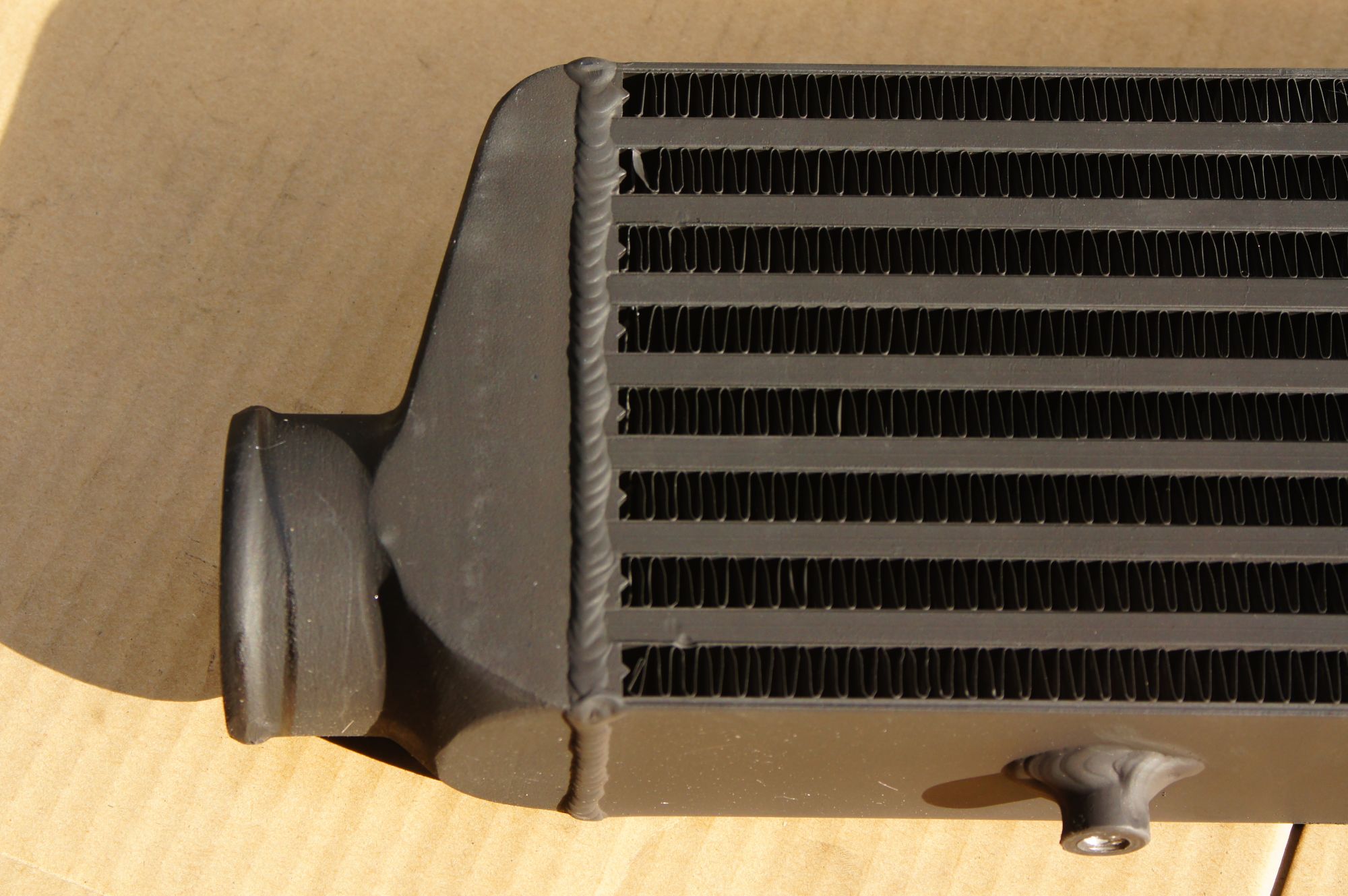
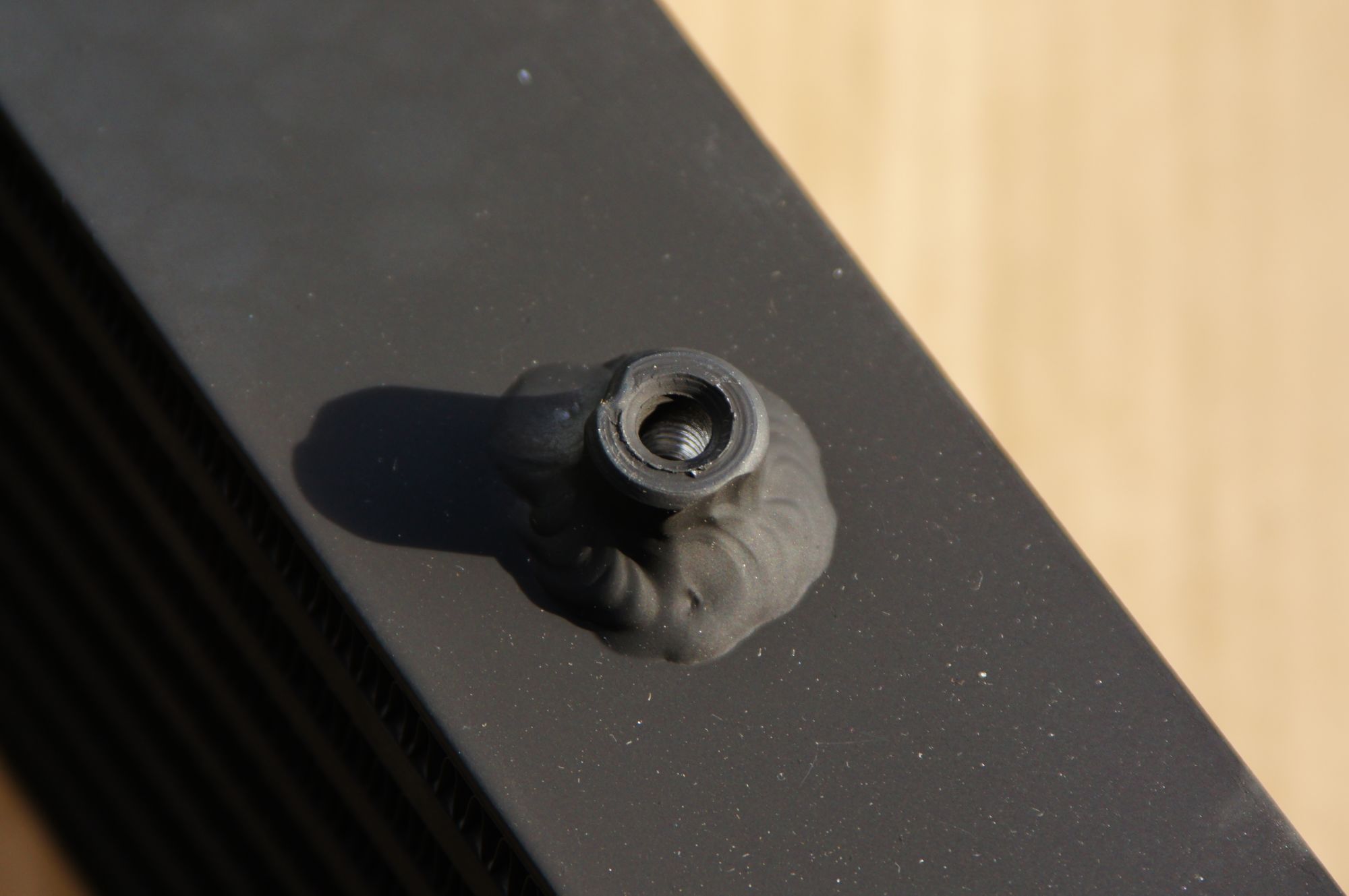
I'm surprised by the quality. Everything looks pretty decent. Welding isn't perfect, but nothing terrible.
The piping is as expected. Powder coating looks good, but is has small scuffs from shipping.
1. It's difficult to keep boost below 6 psi.
2. IATs in this time of year are far worse than expect (~170 cruising in the afternoon)
I should have seen it coming, but all I saw was dollar signs. Moving on I ordered an intercooler from eBay seller dptmotorsport.
27"x5 5"X2 5" Aluminum Black Fmic Bar Plate Front Mount Turbo Intercooler | eBay
It was a shot in the dark. I didn't get a recommendation from anywhere, it literally was the cheapest example with the specs I wanted (2.5" in/out and black)
Also ordered a piping kit from cxmustang's eBay store.
2 5" inch DIY Aluminum 8pcs Turbo Intercooler Piping Pipe Kit Black Blk | eBay
This one wasn't the cheapest, but it was the cheapest one that looked like half way decent quality couplers and piping. Also black.
Plus I had to buy the following to make everything work:
-1.25" x 20" flex radiator hose
-2" to 2.5" 90 degree silicone reducing elbow to adapt to my 2" turbo outlet
-3/8" NPT bung for IAT sensor
-1" OD tube to weld on a bung for BOV
-.75" OD tube to weld on a bung for IACV
All totaled, DIY intercooler should be $206
The only problem is I sold my TIG welder to buy a new one and shipping is delayed. Install is delayed until next weekend.
Pics of the intercooler and piping:
I'm surprised by the quality. Everything looks pretty decent. Welding isn't perfect, but nothing terrible.
The piping is as expected. Powder coating looks good, but is has small scuffs from shipping.
Reply
 0
0

0
Thread Starter
Junior Member
iTrader: (1)
Joined: Jul 2013
Posts: 64
Total Cats: 7
From: Jacksonville, FL
Update on the project: the intercooler is installed, but not really.
Using the piping kit, I fabbed the intercooler pipes. I opted to weld what I could over using the silicone couplings.
I also fabbed some brackets for mounting the intercooler. It's mounted to the same mounting point as the A/C condenser.
Everything looked good and it was time for a test drive. On the first trip out I was having trouble getting boost pressure. I couldn't get over 0psi.
I came back and reconfigured some things, but the problem persisted.
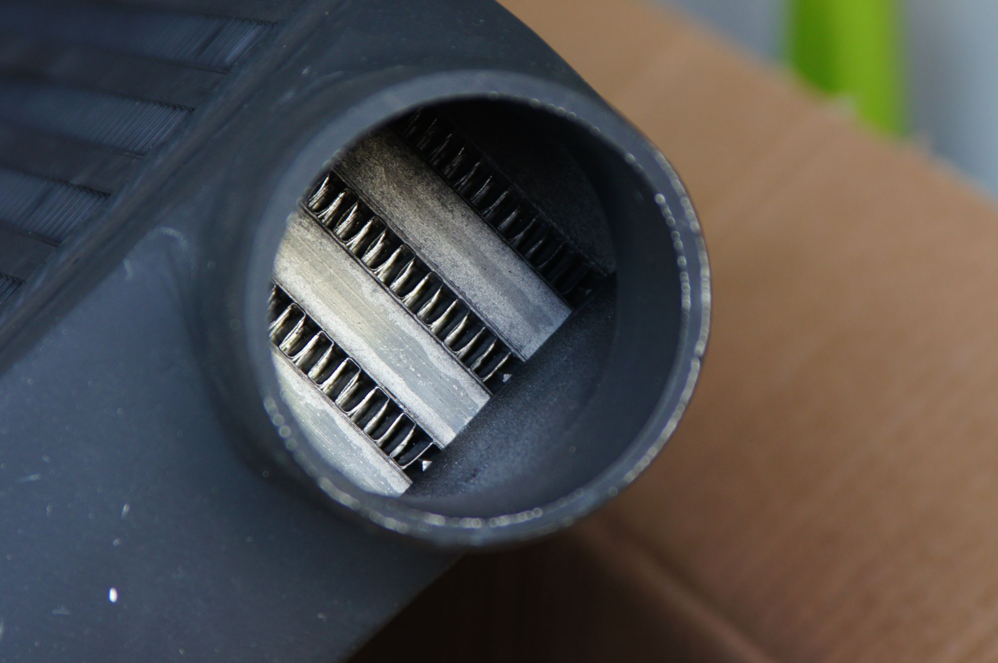
I injured my thumb, had vacation, and became otherwise busy for the next few weeks. Today I revisited the miata with a new idea: the intercooler is restricting flow. I simply replaced the intercooler with a straight piece of pipe and it was like magic. I suddenly had boost again.
Time to replace the intercooler.
DO NOT BUY THIS INTERCOOLER: DPT Motorsport 27"X5.5"X2.5" Black FMIC
Using the piping kit, I fabbed the intercooler pipes. I opted to weld what I could over using the silicone couplings.
I also fabbed some brackets for mounting the intercooler. It's mounted to the same mounting point as the A/C condenser.
Everything looked good and it was time for a test drive. On the first trip out I was having trouble getting boost pressure. I couldn't get over 0psi.
I came back and reconfigured some things, but the problem persisted.
I injured my thumb, had vacation, and became otherwise busy for the next few weeks. Today I revisited the miata with a new idea: the intercooler is restricting flow. I simply replaced the intercooler with a straight piece of pipe and it was like magic. I suddenly had boost again.
Time to replace the intercooler.
DO NOT BUY THIS INTERCOOLER: DPT Motorsport 27"X5.5"X2.5" Black FMIC
Reply
0
0


Thread Starter
Junior Member
iTrader: (1)
Joined: Jul 2013
Posts: 64
Total Cats: 7
From: Jacksonville, FL
My BOV was still operating when the intercooler was installed. BOV was between the IC and the turbo. To me that means I had boost pressure before the IC.
Also, I could hear the compressor wheel stall out once I hit 0psi. It sounded very restricted to me, and once I installed the test pipe in place of the IC, the sound returned to normal.
Reply
0
0

Thread Starter
Junior Member
iTrader: (1)
Joined: Jul 2013
Posts: 64
Total Cats: 7
From: Jacksonville, FL
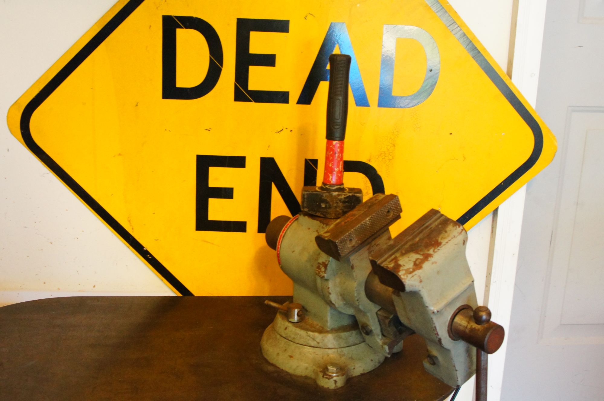
Made some good progress tonight. I got my new intercooler in. CXracing item number 0049. Had to make a few modifications for it to go in place of the DPT brand intercooler. By the way, DPT is working with me to give me a refund. It's currently in the mail back to DPT. We'll see if they actually give me a refund without any hastle.
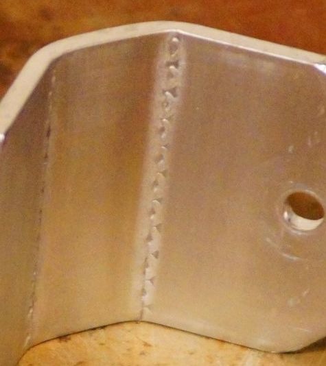
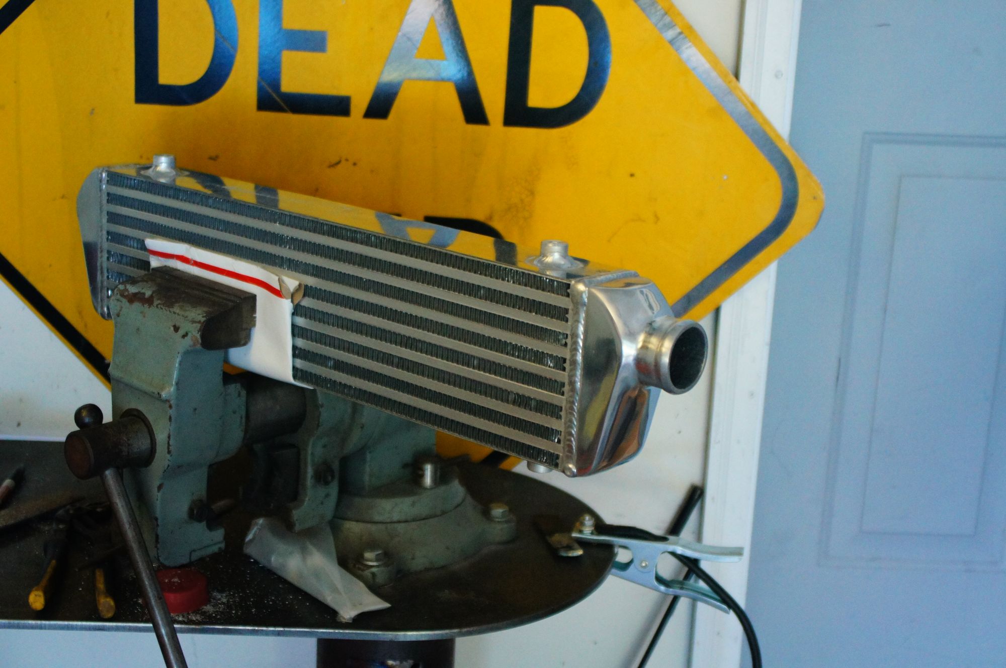
The CXracing intercooler has 2 inch inlet/outlet, but I wanted 2.5". They didn't have one on their site that was the same core size with 2.5 inch in/out, so I just cut the 2 inch nipples off, and welded on some of the scrap ends I had from the intercooler piping kit. I also bent up some new brackets and welded those on as well. I took a page from the BEGi book for the new mounting location.
CXracing item number IC0049
Cut the 2 inch inlet/outlet off
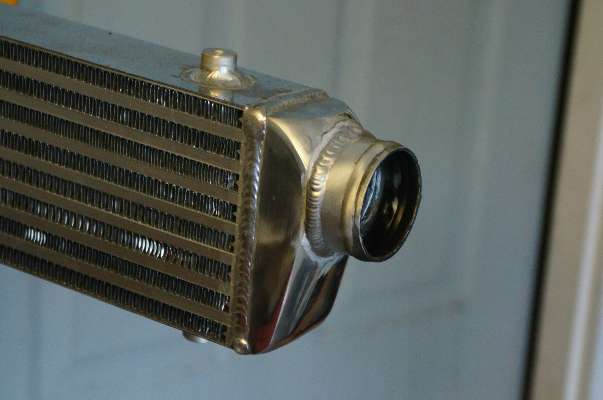
Welded on some left over 2.5 inch intercooler piping to work with the piping already on the car
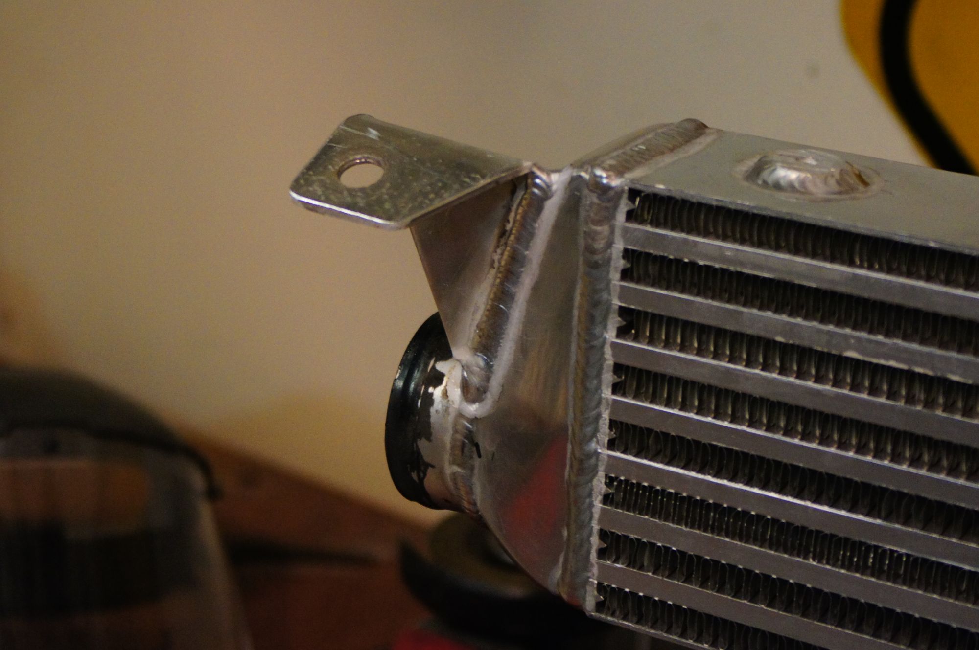
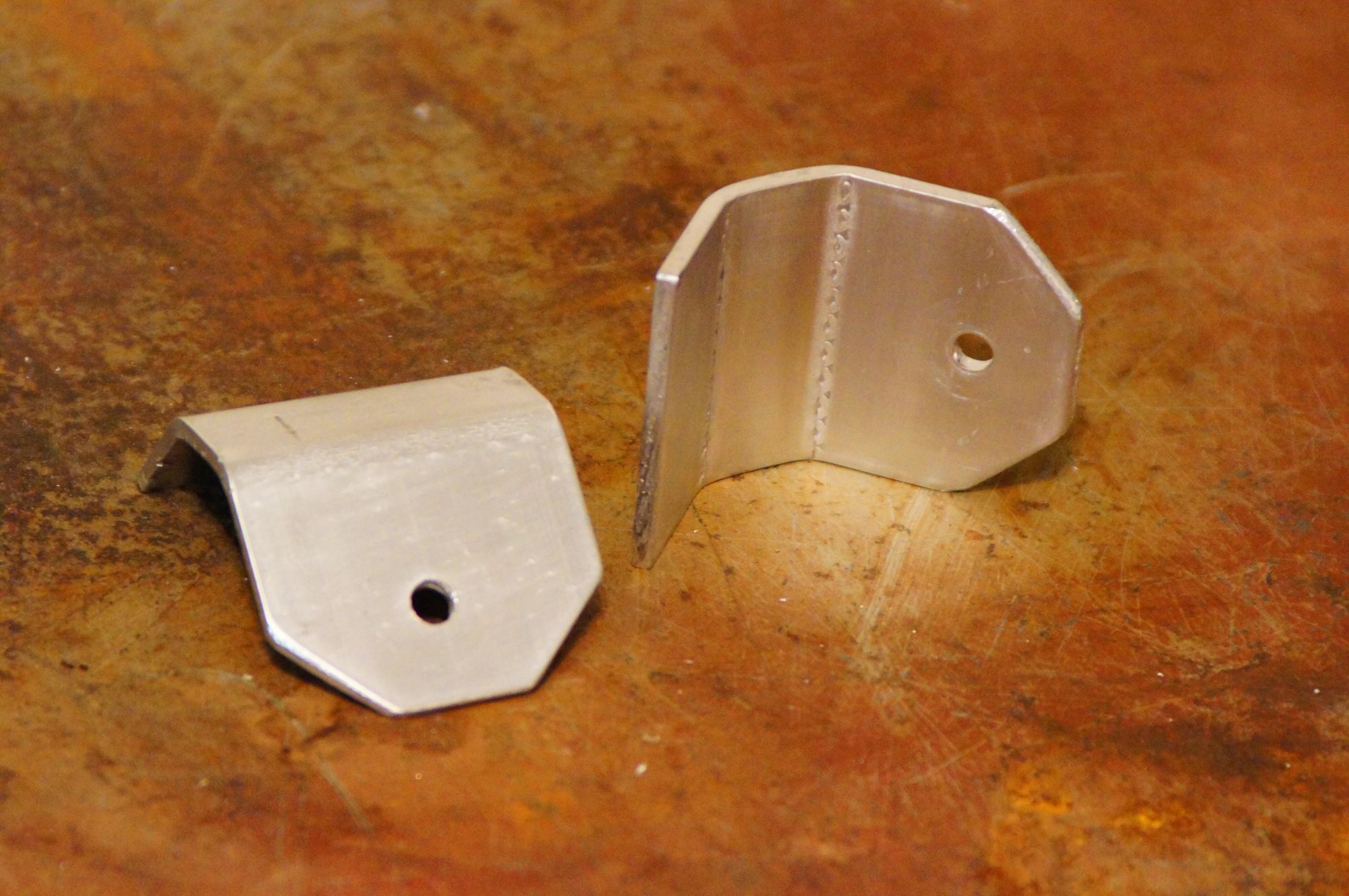
New brackets made to bolt to baby teeth mounting location. Much more appropriate than my previous setup.
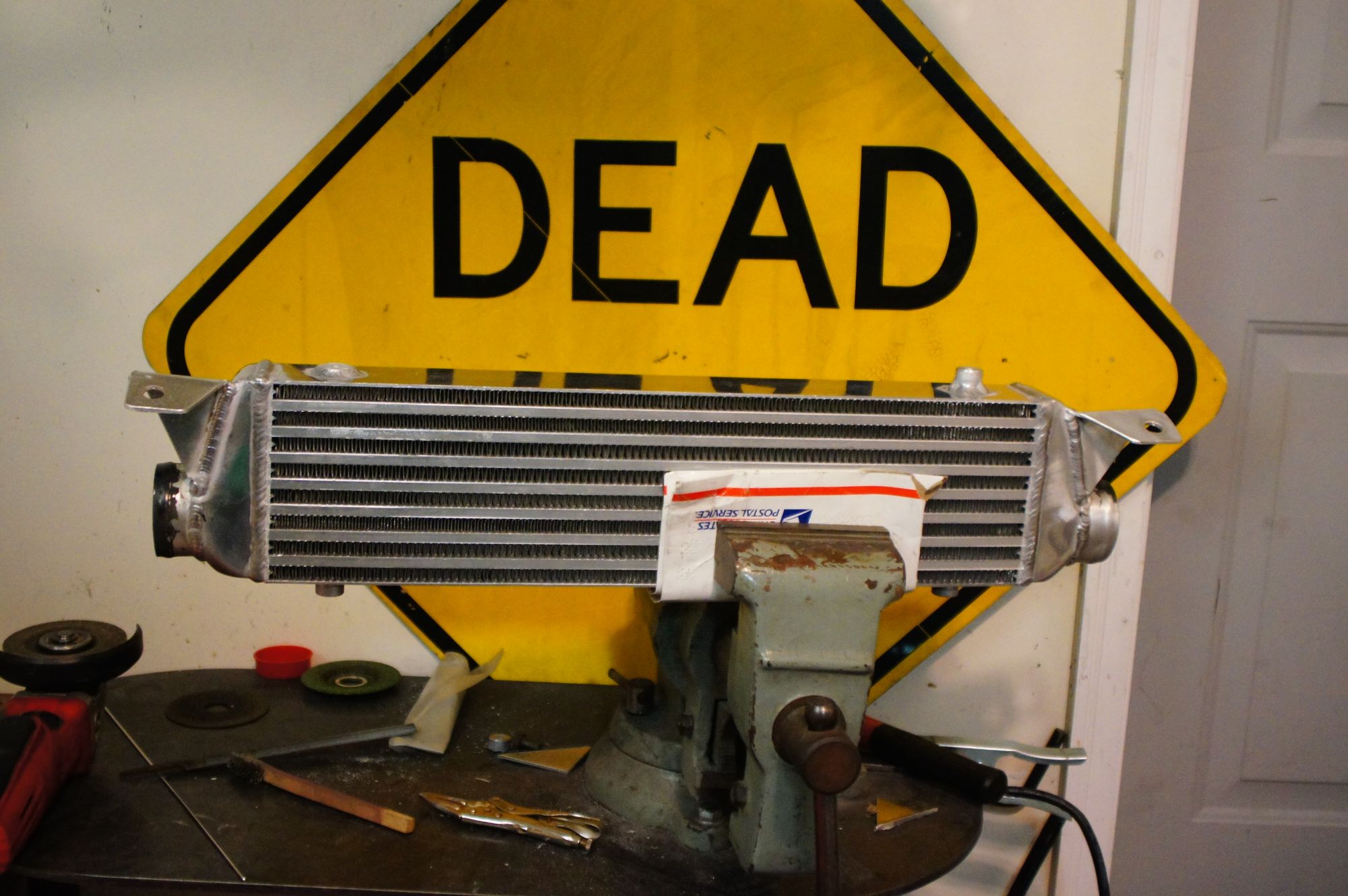
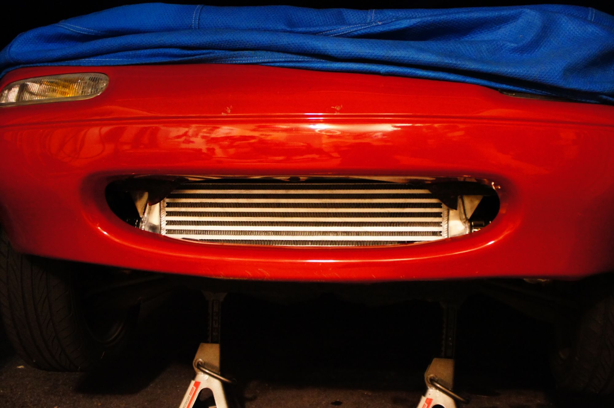
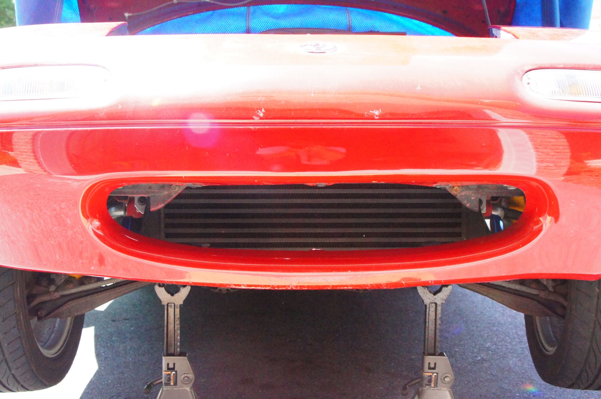
Mounted up and ready for a test ride
New intercooler works beautifully. I finally got the chance to tune my EBC. I've attached my current tune, and the data log from my final 3rd gear pull when tuning EBC. Keep in mind that I still have stock exhaust, so my spool is a little slow compared to other T25 equipped miatas. My spark table is the stock table from DIYautotune, and the fuel table is stock with about an hour and a half of autotune this evening after I got the ebc tuned.
Please feel free to take a look at my tune and give me any pointers. I'm a very novice tuner, and look forward to smoothing some things out in the near future like throttle tip in.
The CXracing intercooler has 2 inch inlet/outlet, but I wanted 2.5". They didn't have one on their site that was the same core size with 2.5 inch in/out, so I just cut the 2 inch nipples off, and welded on some of the scrap ends I had from the intercooler piping kit. I also bent up some new brackets and welded those on as well. I took a page from the BEGi book for the new mounting location.
CXracing item number IC0049
Cut the 2 inch inlet/outlet off
Welded on some left over 2.5 inch intercooler piping to work with the piping already on the car
New brackets made to bolt to baby teeth mounting location. Much more appropriate than my previous setup.
Mounted up and ready for a test ride
New intercooler works beautifully. I finally got the chance to tune my EBC. I've attached my current tune, and the data log from my final 3rd gear pull when tuning EBC. Keep in mind that I still have stock exhaust, so my spool is a little slow compared to other T25 equipped miatas. My spark table is the stock table from DIYautotune, and the fuel table is stock with about an hour and a half of autotune this evening after I got the ebc tuned.
Please feel free to take a look at my tune and give me any pointers. I'm a very novice tuner, and look forward to smoothing some things out in the near future like throttle tip in.
Last edited by pshgomiata; Jul 25, 2015 at 12:26 AM.
Reply
0
0
Thread Starter
Junior Member
iTrader: (1)
Joined: Jul 2013
Posts: 64
Total Cats: 7
From: Jacksonville, FL
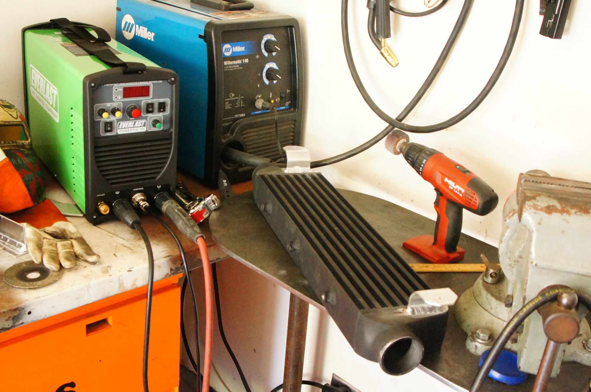
Thanks. The MIG aluminum works pretty well, but by the time you buy a spool gun and argon bottle then you might as well have spent that money on a TIG setup. And I'd highly recommend an Everlast brand machine like I have.
If you've ever got something you need welded that you can ship easily, give me a shout. I really enjoy this kind of work. That goes for anyone.
If you've ever got something you need welded that you can ship easily, give me a shout. I really enjoy this kind of work. That goes for anyone.
Reply
0
0
Thread Starter
Junior Member
iTrader: (1)
Joined: Jul 2013
Posts: 64
Total Cats: 7
From: Jacksonville, FL
In the past couple weeks I built and installed a 3 inch exhaust from the downpipe back to get rid of the stock exhaust, tuned OLEBC/CLEBC for 13 psi, and made a few pulls for some virtual dyno plots.
The exhaust is all stainless with one exception: I started with a flange I stole from the stock mid pipe. Bored that out to 2-1/2" to match the down pipe outlet, then made a reducer to bring the diameter up to 3". The midpipe is from the down pipe back to the axle where I have a v-band flange that connects the midpipe to the muffler. Muffler is the 22" Magnaflow 12578. Then it's 3 inch out the tail pipe.
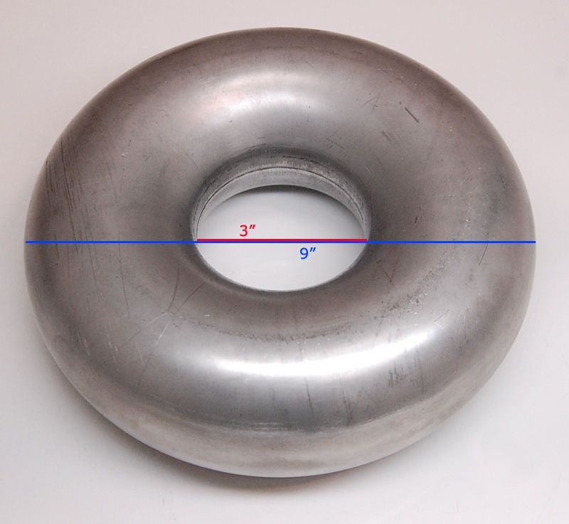
For bends I used a 360 degree mandrel bent donut. The large muffler needed the tightest bends I could find to work without a 180 loop on the muffler inlet. Several things are required to fit this muffler without the 180 loop:
- 3 inch radius bends
- Rotate muffler 10 degrees
- Trim the muffler in/out to weld bends closer to the muffler case
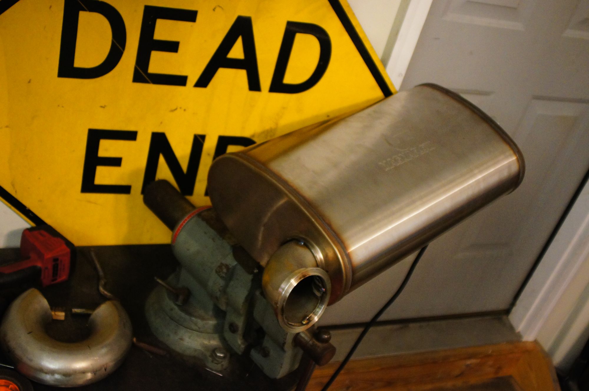
Magnaflow 12578
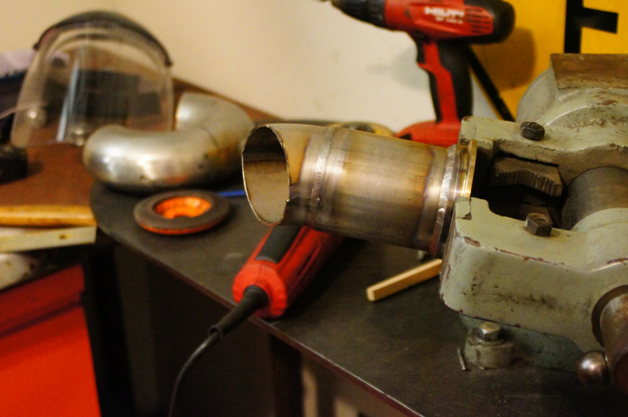
I enjoyed having something round to weld, finally. I'm a pipe welder by trade, but now I have an office job. Felt nice to get back into walking the cup around some elbows and flanges.
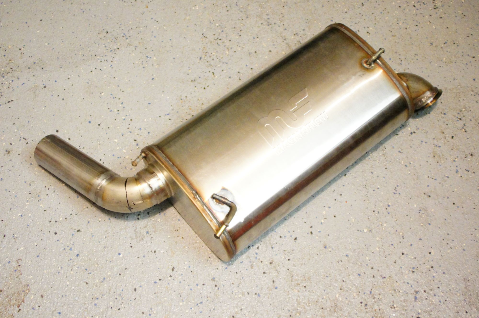
I trimmed the stock exhaust hangers down and reused them on the magnaflow muffler
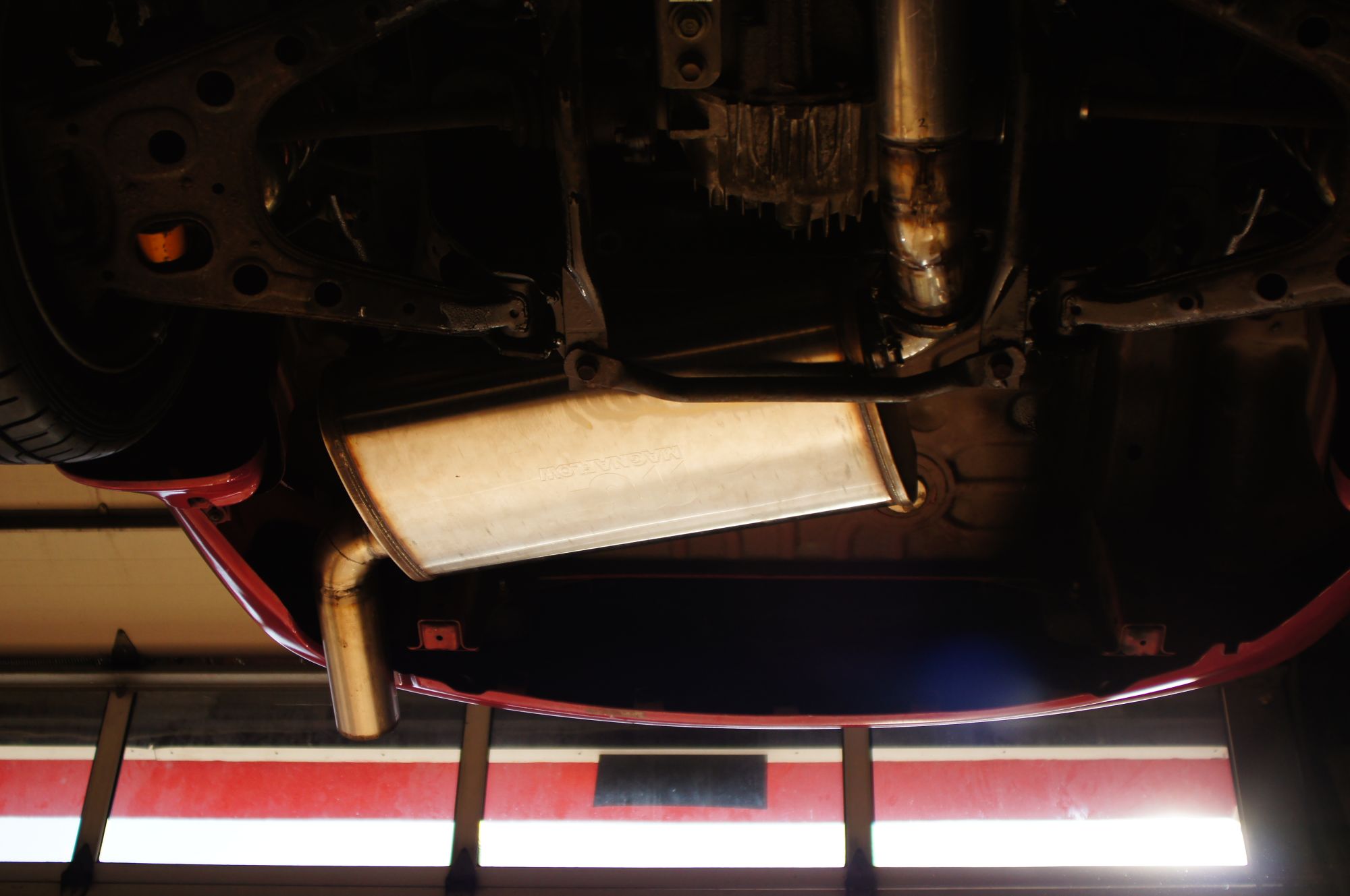
The muffler has about 1/2 inch clearance between the lower subframe brace and the sway bar above it. With the stock hangers, it bangs around a bit. Poly hangers will be installed soon to reduce movement.
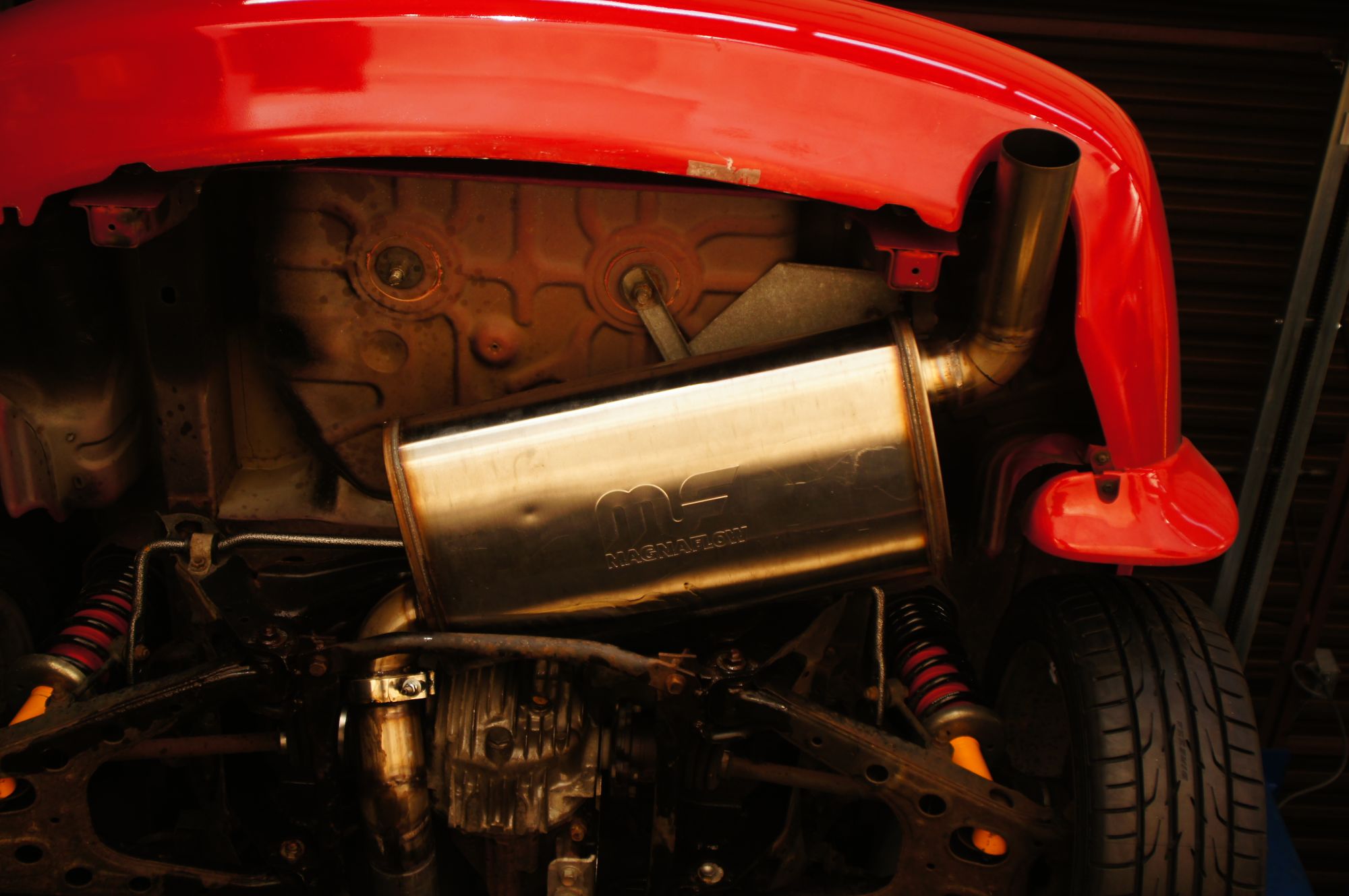
You can see that the outlet did not need to be trimmed flush with the muffler. If I had to do it again, I would move the muffler closer to the tail pipe to allow more clearance around the subframe on the inlet side.
The exhaust is all stainless with one exception: I started with a flange I stole from the stock mid pipe. Bored that out to 2-1/2" to match the down pipe outlet, then made a reducer to bring the diameter up to 3". The midpipe is from the down pipe back to the axle where I have a v-band flange that connects the midpipe to the muffler. Muffler is the 22" Magnaflow 12578. Then it's 3 inch out the tail pipe.
For bends I used a 360 degree mandrel bent donut. The large muffler needed the tightest bends I could find to work without a 180 loop on the muffler inlet. Several things are required to fit this muffler without the 180 loop:
- 3 inch radius bends
- Rotate muffler 10 degrees
- Trim the muffler in/out to weld bends closer to the muffler case
Magnaflow 12578
I enjoyed having something round to weld, finally. I'm a pipe welder by trade, but now I have an office job. Felt nice to get back into walking the cup around some elbows and flanges.
I trimmed the stock exhaust hangers down and reused them on the magnaflow muffler
The muffler has about 1/2 inch clearance between the lower subframe brace and the sway bar above it. With the stock hangers, it bangs around a bit. Poly hangers will be installed soon to reduce movement.
You can see that the outlet did not need to be trimmed flush with the muffler. If I had to do it again, I would move the muffler closer to the tail pipe to allow more clearance around the subframe on the inlet side.
Last edited by pshgomiata; Aug 15, 2015 at 03:51 PM.
Reply
0
0
Thread Starter
Junior Member
iTrader: (1)
Joined: Jul 2013
Posts: 64
Total Cats: 7
From: Jacksonville, FL
Once I got the EBC tuned I finally got some decently clean 3rd gear pulls to plot some virtual dyno graphs. I'm not sure how accurate the high HP numbers are, but I like what I'm seeing with the torque. Hopefully I can get a professional tune soon and see what it looks like on a dyno.
10psi at 3400rpm
13psi at 3700rpm
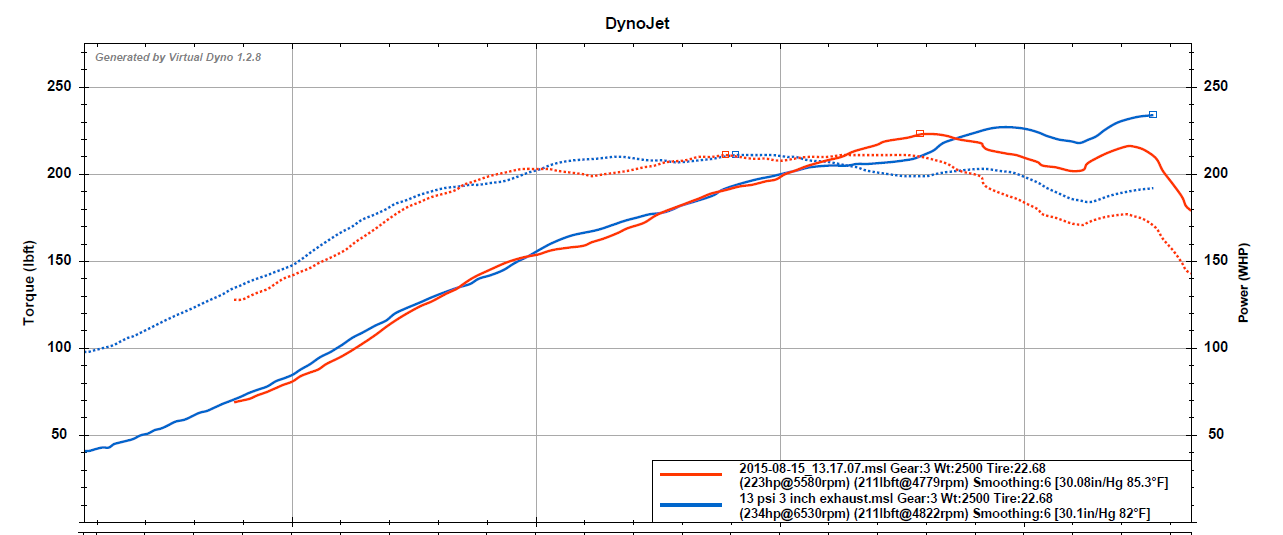
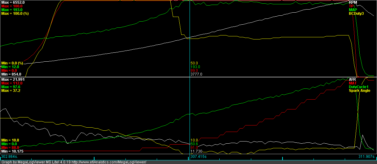
First clean pull
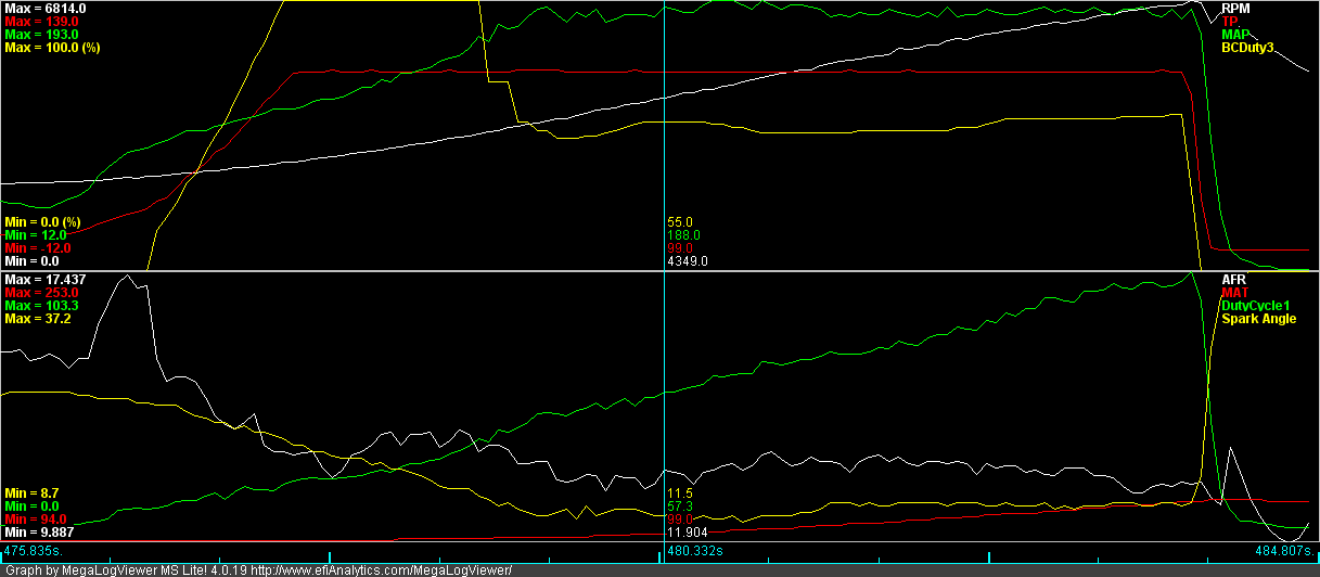
Clean pull after reducing kpa spike at 3700rpm. Same road, opposite direction.
10psi at 3400rpm
13psi at 3700rpm
First clean pull
Clean pull after reducing kpa spike at 3700rpm. Same road, opposite direction.
Last edited by pshgomiata; Aug 15, 2015 at 03:36 PM.
Reply
0
0
Thread Starter
Junior Member
iTrader: (1)
Joined: Jul 2013
Posts: 64
Total Cats: 7
From: Jacksonville, FL
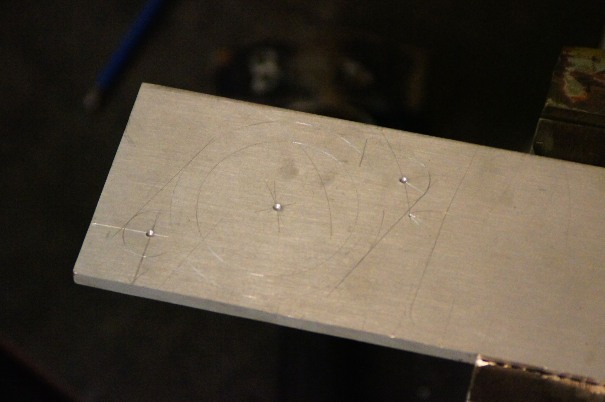
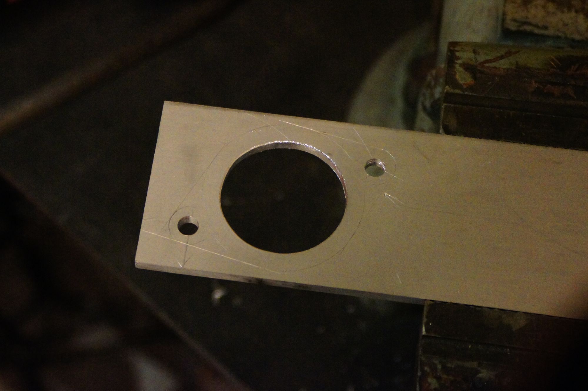
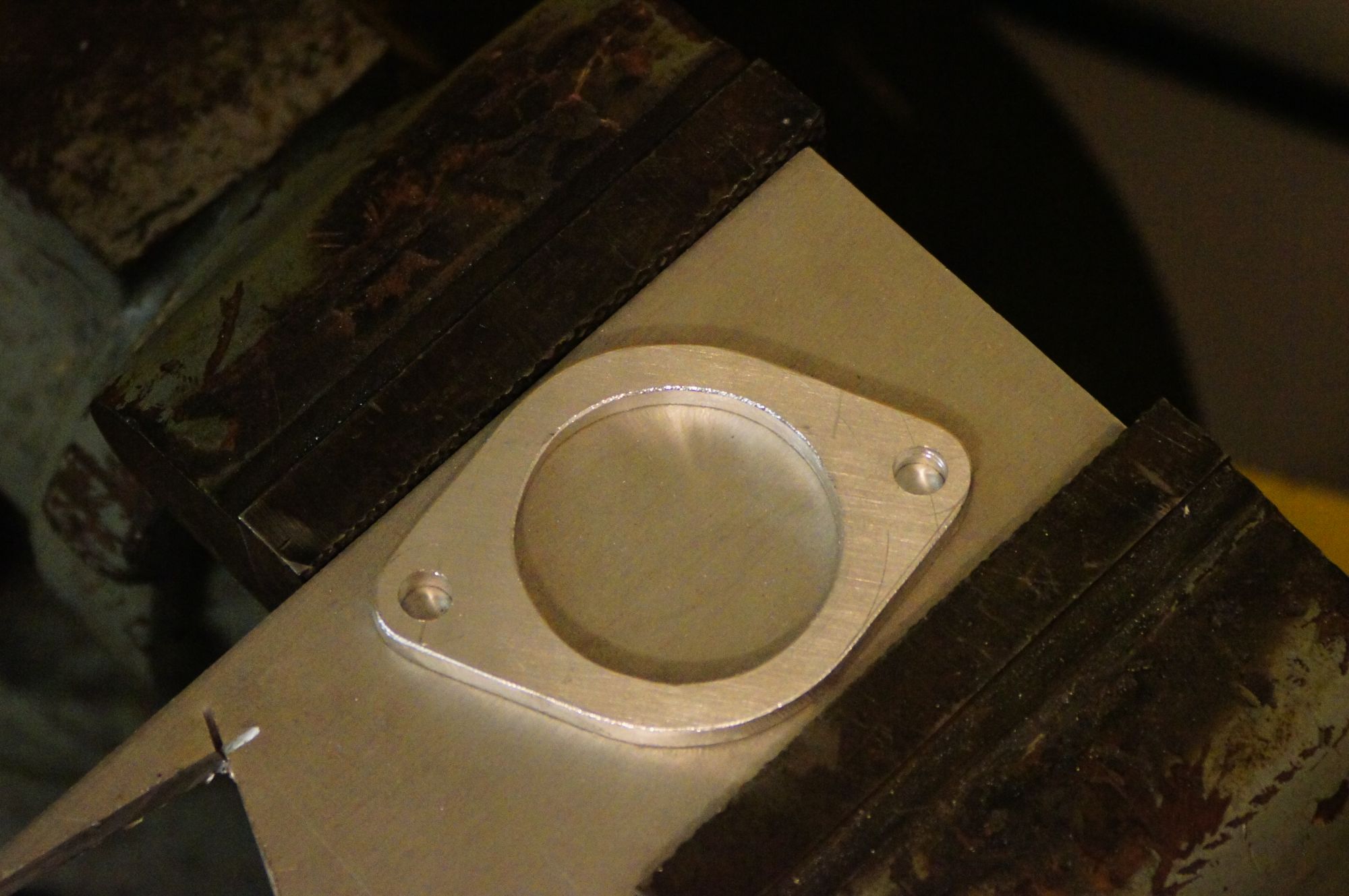
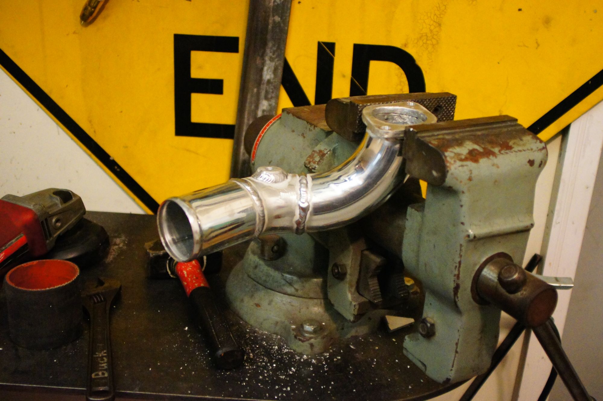
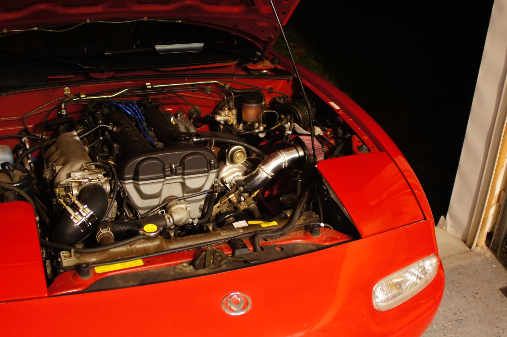
The intake I started with was a simple, carbon steel flange and neck to mount a filter right on the front of the compressor housing. I wanted to source intake air from not directly behind the radiator and I wanted something I can plumb the BOV into at some point. A homemade flange and some ebay mandrel bent 2-1/4" tubing worked nicely.
Reply
0
0
Reply
1
1
Thread Starter
Junior Member
iTrader: (1)
Joined: Jul 2013
Posts: 64
Total Cats: 7
From: Jacksonville, FL
Make sure your filter is big enough: https://www.miataturbo.net/build-thr...e3/#post706313
Thanks for the link. That's some excellent info.
EDIT: Just ordered a K&N RU-1100
Last edited by pshgomiata; Aug 17, 2015 at 12:08 AM.
Reply
0
0
Thread Starter
Junior Member
iTrader: (1)
Joined: Jul 2013
Posts: 64
Total Cats: 7
From: Jacksonville, FL
A lot has happened since I last posted, I'll try to keep it short.
Soon after my last post I blew a head gasket. I was being a dummy and drained some coolant to adjust some hoses, then got distracted and neglected to refill the coolant before a short test drive. Once I figured out the head gasket was blown, I pulled the head and found water inside cylinders and exhaust. Definitely a blown head gasket. Machined/measured the head and block and reinstalled a new head gasket. The machine shop said that there was little to no warping in the head, but the ground a couple thou good measure.
After that, I could not hold boost above 8 psi. A dry compression test showed all four cylinders under 120psi. Wet compression test improved numbers dramatically, and a leak down test confirmed that the piston rings were leaking compression. The car was at least still running, and life was busy so I put off a rebuild for the time being. I've since moved to FL, and now have a much larger garage space and more time on my hands. Time to dig into the motor to see what the problem is.
Now I'm no engine builder; I'm barely a shade tree mechanic, but I can sort of read. I acquired a copy of the Mazda workshop manual and started disassembly. I've been following the directions in the manual pretty closely. All the bearing surfaces, valves, and cylinder walls are still within the specifications of the manual. Not super surprising considering the motor is has less than 65K miles. I'm currently working on reassembling the motor with new bearings, rings, and gaskets. It should be back in the car in the next week or so. I'll attach some potato pictures of my progress.
While the block, head, cylinders, and valves were very dirty, my untrained eye didn't see any obvious signs of damage. Please let me know if you spot something out of the ordinary.
Reply
0
0

Thread
Thread Starter
Forum
Replies
Last Post
russian
Miata parts for sale/trade
6
Oct 8, 2015 03:01 PM


