When you click on links to various merchants on this site and make a purchase, this can result in this site earning a commission. Affiliate programs and affiliations include, but are not limited to, the eBay Partner Network.
Quote (loosely translated) “Ze turbo is good and ze supercharger is good, so having both must be very good!” Unemployed VW TSI project manager
Who would have thought, that we would ever see OEM twin charged systems on the market? The VW twin charged TSI engine is a bit of an enigma though. Why would you add all that complexity and cost, just to get slightly more power and 6% better fuel economy? I think Volvo is doing a bit better in this regard, but they still may not be successful.
Certainly Eaton think there is future in this technology, since they have developed a supercharger specifically for twin charging. (TVS v2) Read about it here http://www.google.ca/url?sa=t&rct=j&...e91uf6pSv22sHA
I have always wanted to do a twin charged build.It certainly is not an easy build, but I have always wondered what the performance would really be like, and very little seems to be shared from the few that have successfully done this (although recently I have hooked up with a board member here, who has a twin charged system working). I have not wanted to tackle this project because I thought the control system would be too complex. I then connected with a chap from Sweden, who had twin charged his Volvo with basically just 1 valve controlling things. The trick is to have the supercharger blow through the turbo, with the disadvantage being that you don’t get compound boosting. I don’t have access to E85, so I am am not that concerned about compound boosting. He was using a Volvo valve out of a boat. It seemed like a good plan.
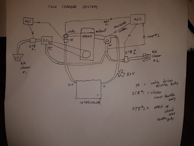
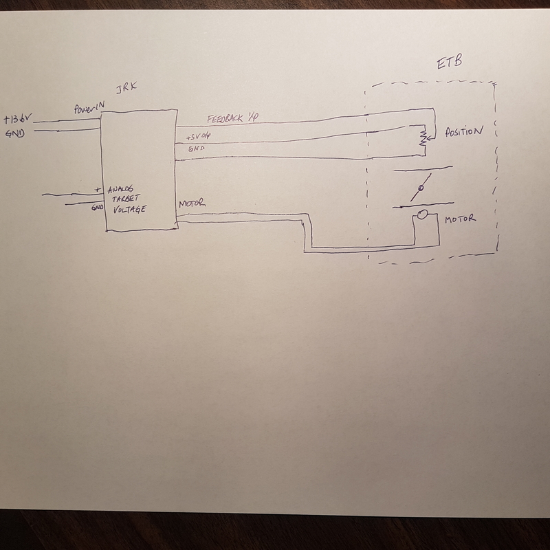
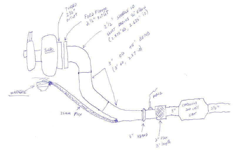
Here is the system: (note in this drawing the Volvo valve has been replaced with ETB#2)
Some twisted logic for tackling this; -my previous builds have not been reliable, mostly due to the superchargers breaking. I am running them well above "normal" SC boost levels. This will allow me to get better HP, yet still not drive the supercharger too hard. (ie, this could actually be more reliable) -I'm looking for another project. -for science. -this can be done in stages, so I will be able to drive the car during build. -doing another build with just a leading edge turbo (EFR), or leading edge supercharger (whipple), would likely be more expensive.(well at least until things start breaking)
Some logic for not tackling this; -very complex build which means high risk of not getting things working or running reliably. -lots of time and effort for what real gain? -blah blah blah blah.
Supporting mods:
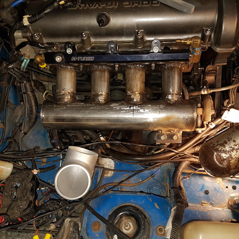
Fuel – Walbro255, ID750 injectors, M-Tuned rail, stock press regulator.
Spark –Dual MSD-6A’s, driving stock 90 coils.
Computer –MS2 on custom PCB
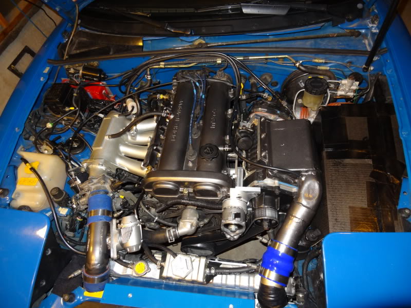
Engine –forged rods and oil pump, coated stock 96 pistons, 99 head with 1mm oversize intake valves and minor porting/deshrouding.
Drivetrain –centerforce clutch/pp, 6 speed, 4.1 torsen.
Exhaust 2.5” magnaflow rear muffler and resonator with carsound 200cell cat.
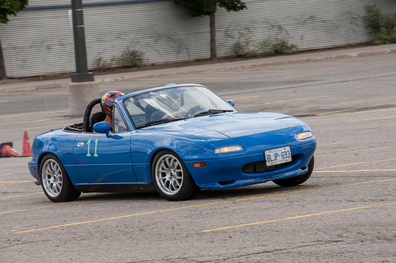
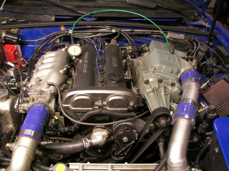
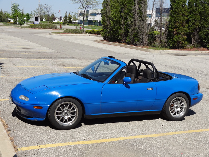
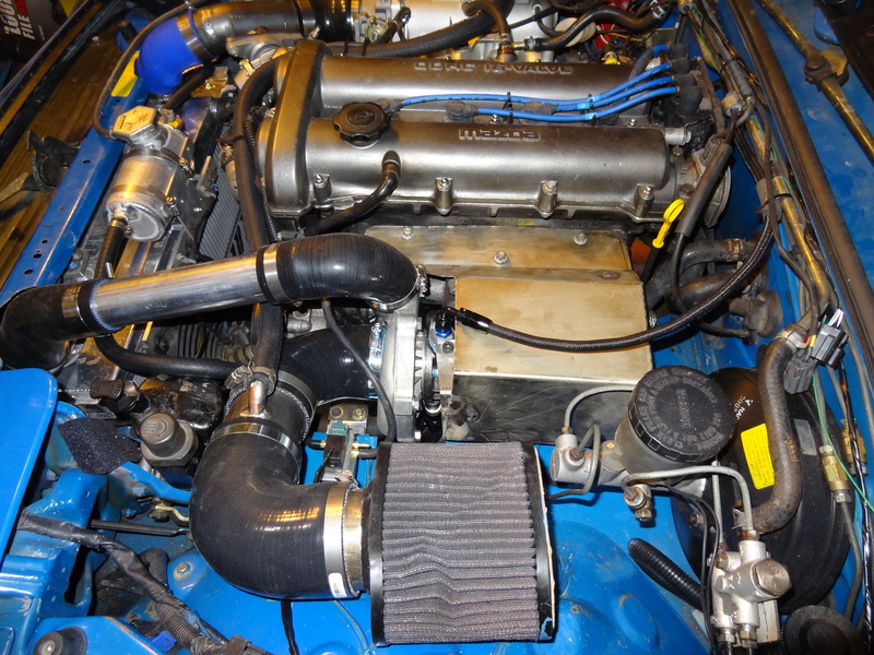
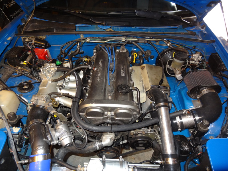
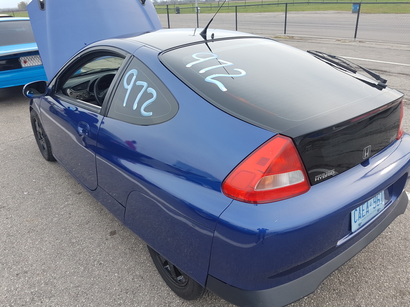
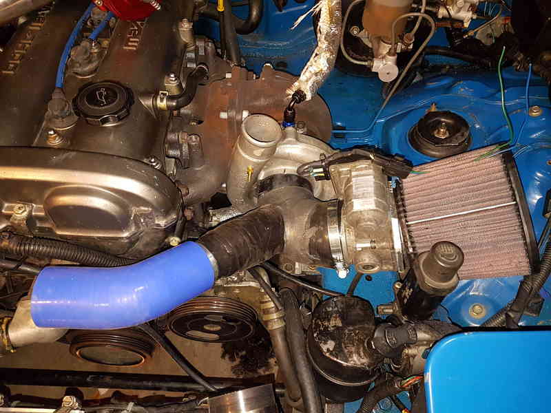
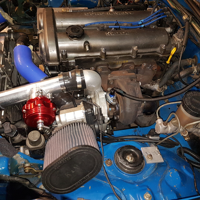
Recent car picture
The bad news:
I cannot fab stuff like say Patsmx5. In fact, I am rather slow and at times need to remake stuff when the first attempt fails.
The good news:
I started this project in the fall of 2015, and I expect to be done in the spring of 2017.
So I will update this thread with progress to date, as quick as I am able.
Good luck on the build! I will be following your build to see what's next! I like how your going to plumb the new setup, the simplicity will make the control system easy as you say.
Right on dude! Didn't realize our cars were the same color.
Yah! Mariner Blue is the best Miata color ever! (ok, kidding)
Originally Posted by patsmx5
Good luck on the build! I will be following your build to see what's next! I like how your going to plumb the new setup, the simplicity will make the control system easy as you say.
Thanks, I probably need all the luck I can get.
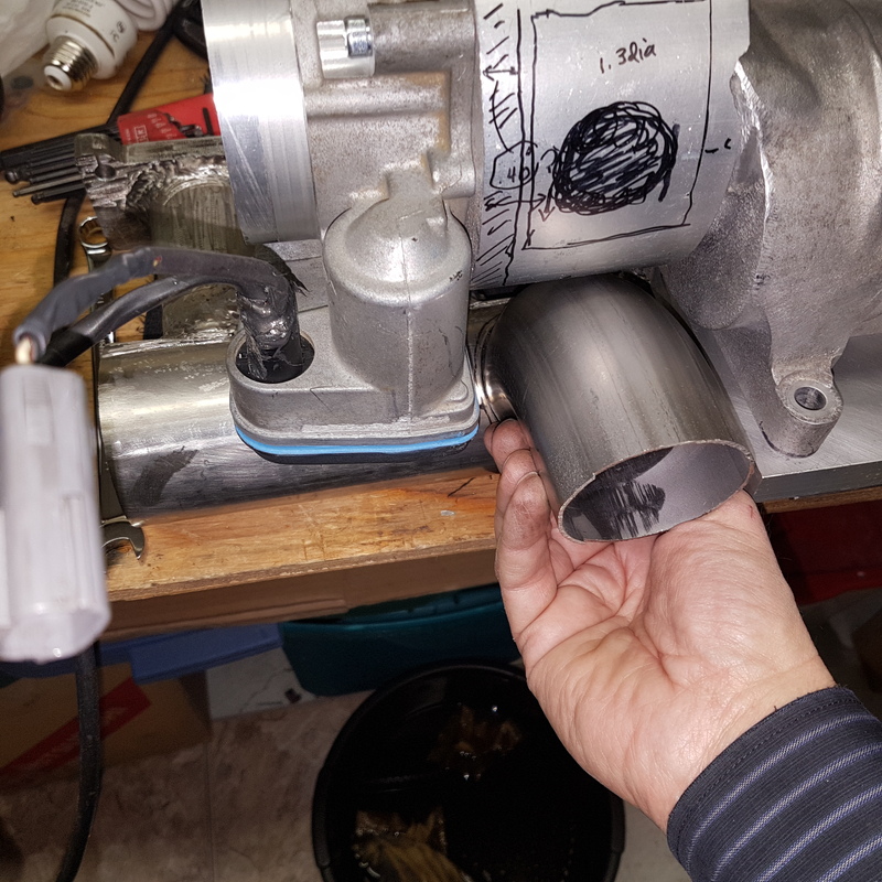
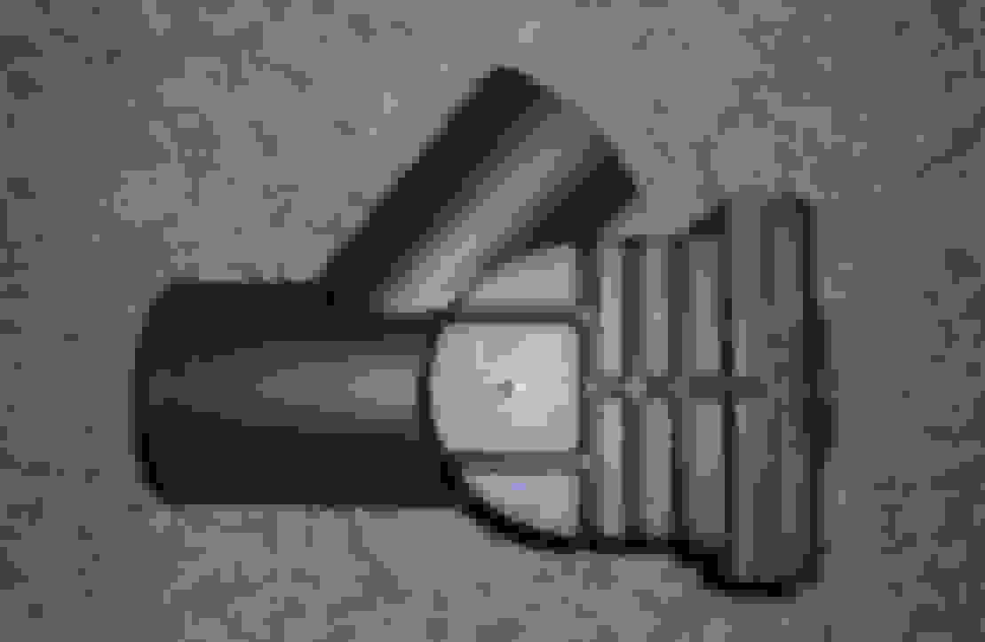
So the first thing I wanted to do, is lay my hands on one of the Volvo valves.Fortunately, a used one came up on Ebay which I snagged for $65. I got it in my hands and was not impressed.The valve was huge, and it used various sizes of connecting pipes, from 3.1” to 3.4”.It had to be mounted parallel with the ground, since it required gravity to operate. It also employed 3 hose connections, which would not work for my setup.
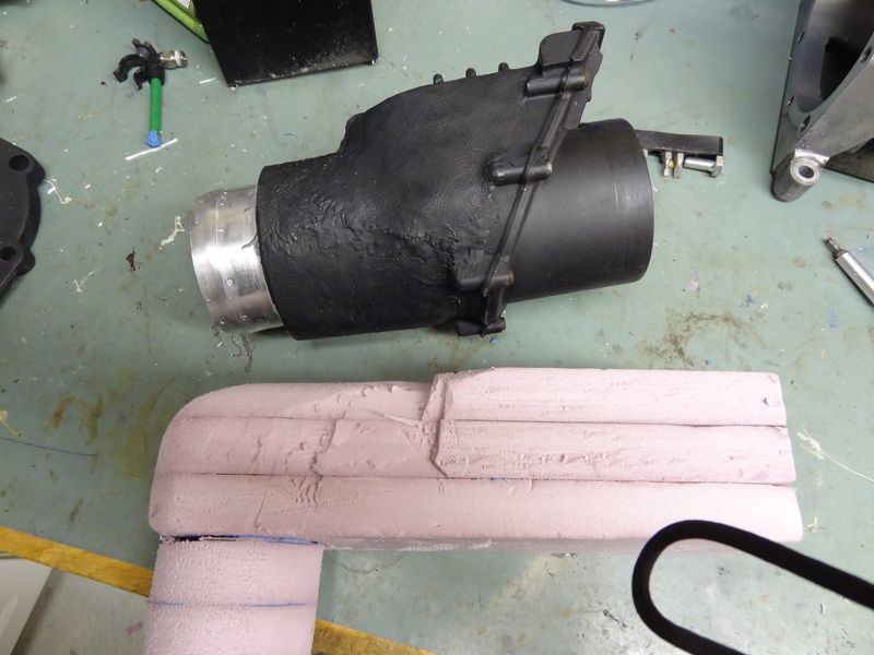
I knew this thing would not fit under the hood for sure, so even though I had no idea if I could ever get it to fit, I decided to work on chopping it down in size. Most of the excess was on the input side of the valve (LHS in picture), so I cut that end off, and rebuilt it using a 3” aluminum pipe, fibreglass mesh and a few tubes of JBWeld glue.
Here is how the valve looked after the downsizing operation.
Unfortunately, later testing would reveal that this thing would still not fit.So I ended up modifying a Nissan Maxima throttle body at a later date.
While playing with the Volvo valve, I tried to hone in on the parts I wanted to use on the build. Unlike a ‘turbo only’, or ‘supercharger only’ build I felt I had more flexibility on how old the technology of the part I was using could be. If the turbo was large and spooled really slowly, then bring it on (as long as it was efficient where I planned on operating it). Same goes with the supercharger, but I did need it to pump a reasonable amount of air at lower engine RPM’s.
I set my initial goals at 200ft/lb at 2000rpm and ~350hp at 7000ish and decided to do the turbocharger part of the build first.
I would purchase and install the parts in the winter of 2016 and run the car, “turbo only” during the summer of 2016, working out any bugs which cropped up.This would also give me the opportunity to build some of the SC parts, during the summer, while still giving me the following winter to finish things off.
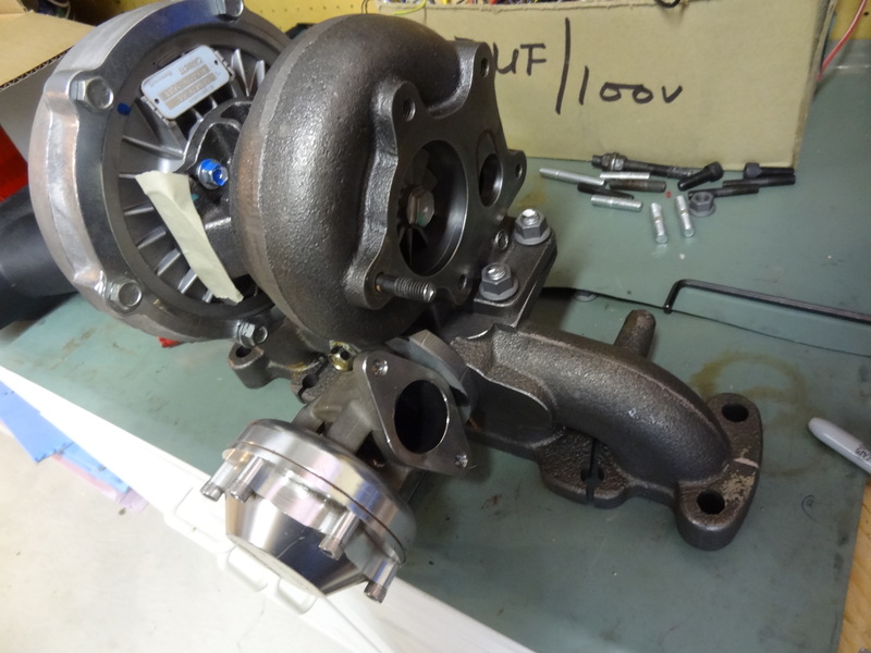
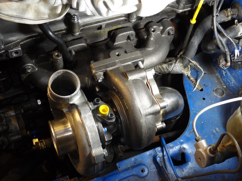
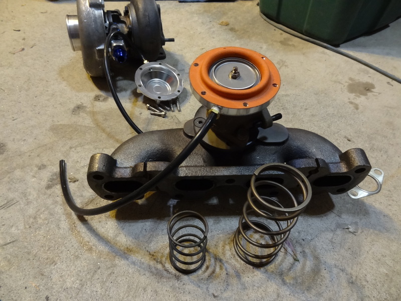
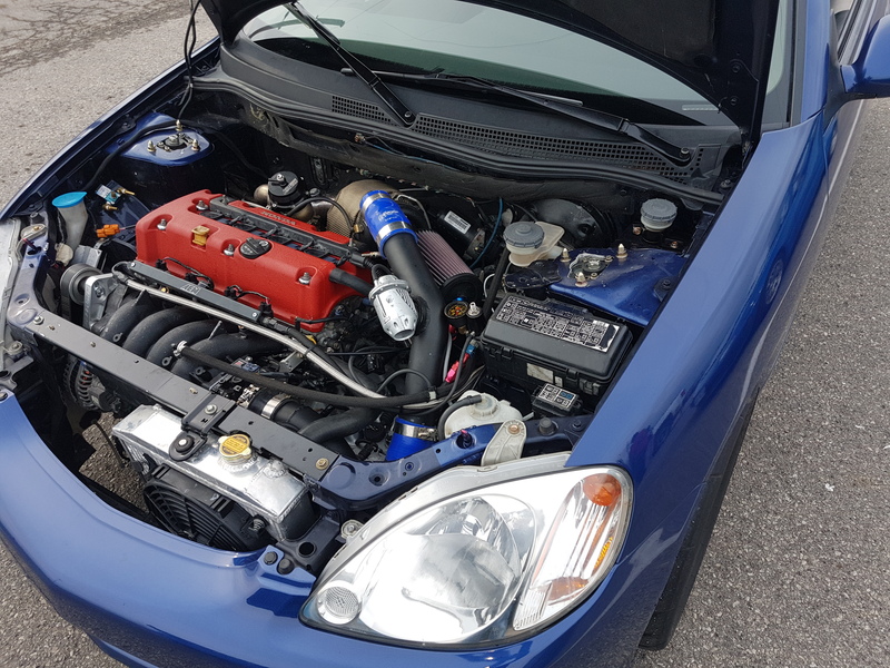
After quite a bit of watching of Kijiji (like Craigslist), I purchased a used but new Garrett T04E .63AR 50 trim turbo with 3 different flanges at a most excellent price along with a Turbonetics 35mm external wastegate. That, with my cloned HKS blow off valve I already had, and the purchase of a cheap cast Ebay manifold made up the kernel of the system.
Nothing like some mid 80’s technology, paired with some crappy China made knock offs to set things off in the right direction.
My only real concern was how well the Ebay cast manifold would flow and if it would hold up.I was confident everything else would work well.(well, I was almost right…)
For a turbo designed in the 80’s, the T04E-50 trim has a pretty efficient compressor.Here is the compressor map with a number of flow points marked. I thought I might need to go as high as 24PSI, but was not initially planning on raising the redline to 7700.
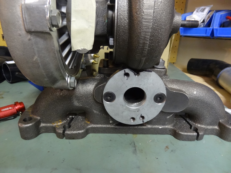
Hmm, using the wastegate mounting holes in this cast manifold, means you have the option of having the exhaust port of the wastegate shooting into the block, or into the turbo itself.So I made an adapter plate, using a 1/2" thick piece of steel.Also, a bit of interference between the turbo compressor side, and the manifold had to be ground away.
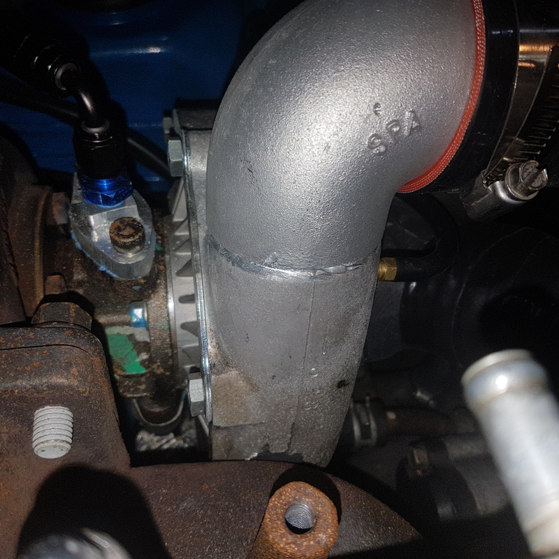
Needed to use one stud in the turbo down pipe flange since the elbow is quite tight.
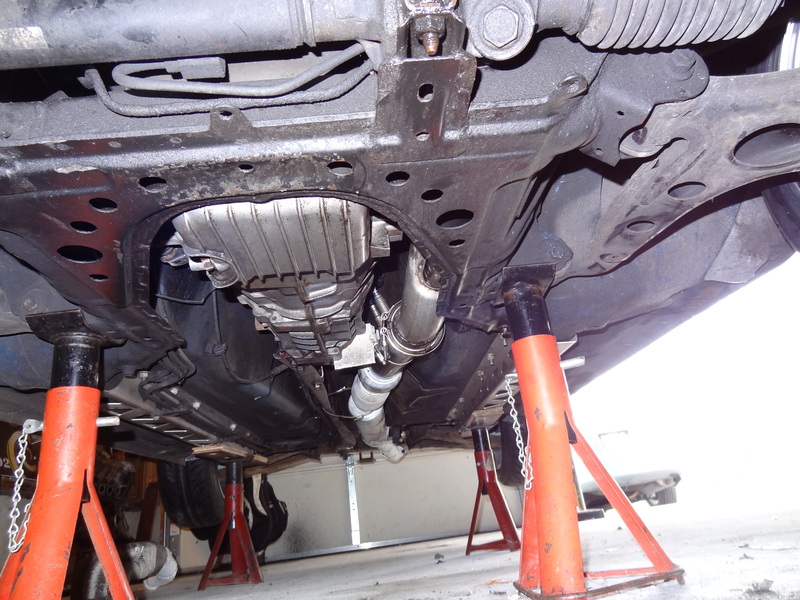
Since I didn’t take any pictures of the downpipe, here is the layout.I was able to coax the 3”od exhaust tubing over the 2.5” short radius elbow, before welding. Also, you will note that the ID of the piping steps up twice.It comes out of the turbo at 2.5”, into the elbow at 2.635” and then into the 3” pipe at 2.87”. Not as good as a transition pipe, but not too too bad.
Had 10mmx1.25 threaded rod from a previous SC build, which I used as studs for the 4 corners of the manifold.The short radius cast stainless elbow, clears the parcel shelf easily.
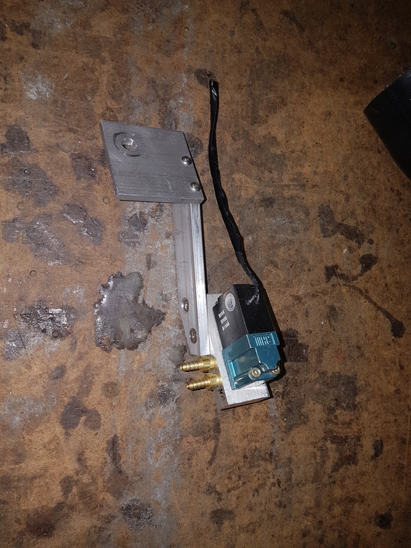
Had some 12v MAC valves kicking around, but needed to make a valve manifold and mount.
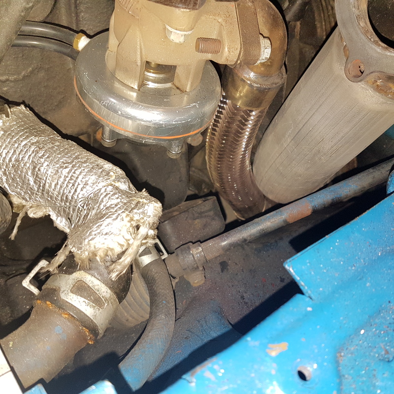
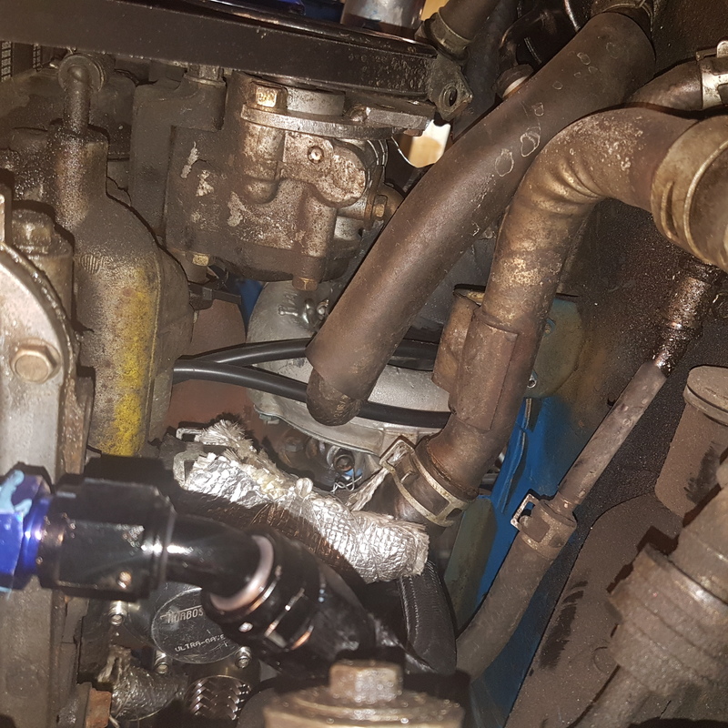
Built the oil in/out flanges for the turbo to attach the AN fittings to.Purchased direct from China (Ebay) the AN hoses and fittings which turned out to be a mistake. They were very difficult to assemble, and the 45D and 90D elbows failed after 3 months.
Hard to tell, but this is a picture of the turbo 8AN drain hose and fitting.The drain hose interfered with the cooling hose, so I ended up modifying the cooling hose mount.
Cut up a stainless dishwasher door for material for the turbo heat shield.It buzzed, so I removed it after a time.
From the CAT on, the exhaust is just 2.5” diameter.The CAT flows the same as a 2.5” pipe, so both the CAT and exhaust would need to be replaced to remove this restriction. So far, I have not found a CAT that will flow close to what a 3” pipe will, so have not figured out what to do long term.
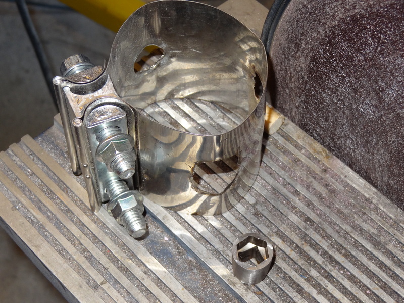
Two tools I found useful. 1.If you buy this manifold, do yourself a favour and grind down a 6 point socket, so you can use a ratchet for every nut holding the manifold to the engine. 2.This band clamp was used to fabricate the down pipe.Use the clamp to hold the 2 pipes that need to be welded in the correct position. Remove the pipe from the car, and tack weld it thru the holes in the clamp.Remove the clamp and test.Then fully weld the joint.Step and repeat.
Next up: Fuel, spark and wastegate PID tuning, and numbers.
There seems to be a lot of discussion on twin charging and compounding lately. It's interesting.
I will be paying attention.
There has been hasnt there. The more I think about it the more I think rocket anti-lag would be easier to do than any sort of successful twin charging system. Rocket anti lag is actually less harsh on the turbo than the normal exhaust gases so you could just have it running all the time.
I was absolutely thrilled with how the v1 prototype of my system worked out. So much so, that if it hadn't been for excessive blow by on #1, I probably would have stuck with it. For my driving style the compound is/was awesome. I am really excited about getting the v2 on the road. Conservative estimates should put me at 240+ lbft under 3K RPM. Never will be a dyno queen champion, but a freakin kick in the pants drive to and from work.
There has been hasnt there. The more I think about it the more I think rocket anti-lag would be easier to do than any sort of successful twin charging system. Rocket anti lag is actually less harsh on the turbo than the normal exhaust gases so you could just have it running all the time.
LOL. I read this earlier, and still smile whenever I think about a rocket being used to drive the turbo. Would you suggest using an afterburner?
Turbo tune and Phase 2: After getting the car back onto the road, and getting a rough tune in, I was disappointed to find that the spring in the wastegate was yielding only 6psi. Attempts to increase this using the EBC in megasquirt resulted in either massive overboost, or wild oscillations.
I was using this procedure for dialling in the PID:
“In my experience with closed loop boost control, I found that you need to lower the P term until you have about 10-15 kPa initial overshoot before trying to tune the I term.Then, add some I and add some P. Each time you increase the I term, increase the P term with about 20% of the increase of I term to keep the system stable Do not touch the D term until you can at least have a kind of flat boost duty. Add some D only to reduce the initial overshoot.”
Another option was to use a higher boost base spring, but I couldn’t find anyone selling anything for this older style unit. I purchased (then returned) a 15psi spring for a Tial unit, but it would not work.
I then found a post with the following suggestion: “Then I realized that LOWERING P reduced the oscillation.Of course this would result in massive over boost. But instead of following the manual again, I decided to add D to reduce overboost while leaving I at zero. So I'd increase D and then not reach my target, then I'd lower P again which results in more over-boost. More D to get rid of the over boost, and so on.” Following this procedure allowed me to dial in the wastegate with reasonable success.
During the summer I ran a few autocrosses and did a few upgrades.
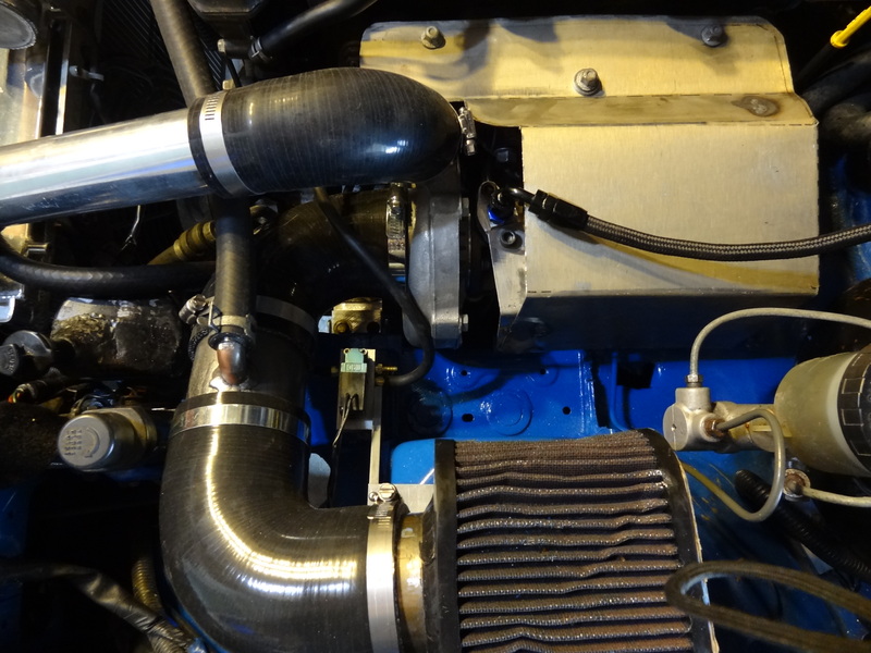
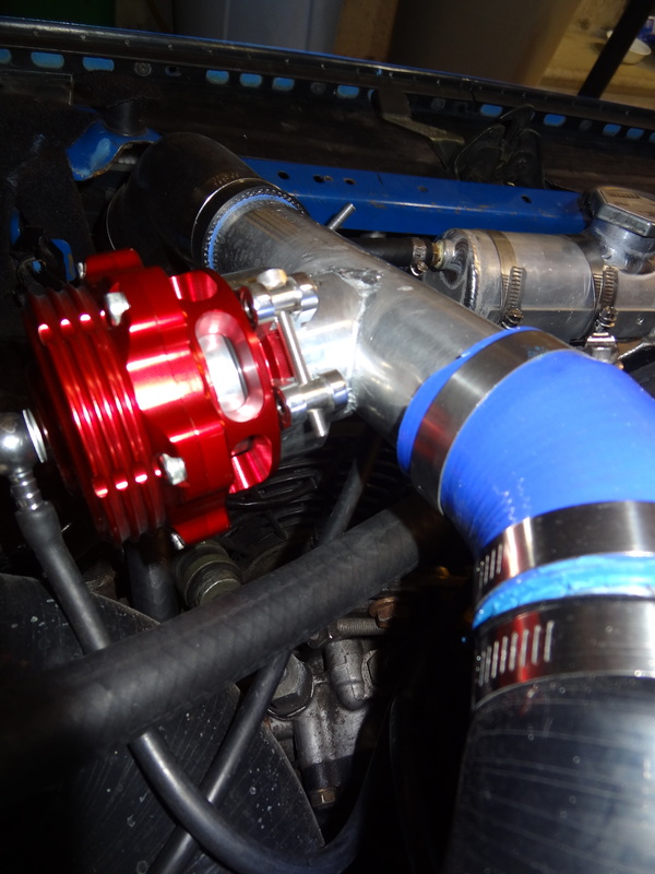
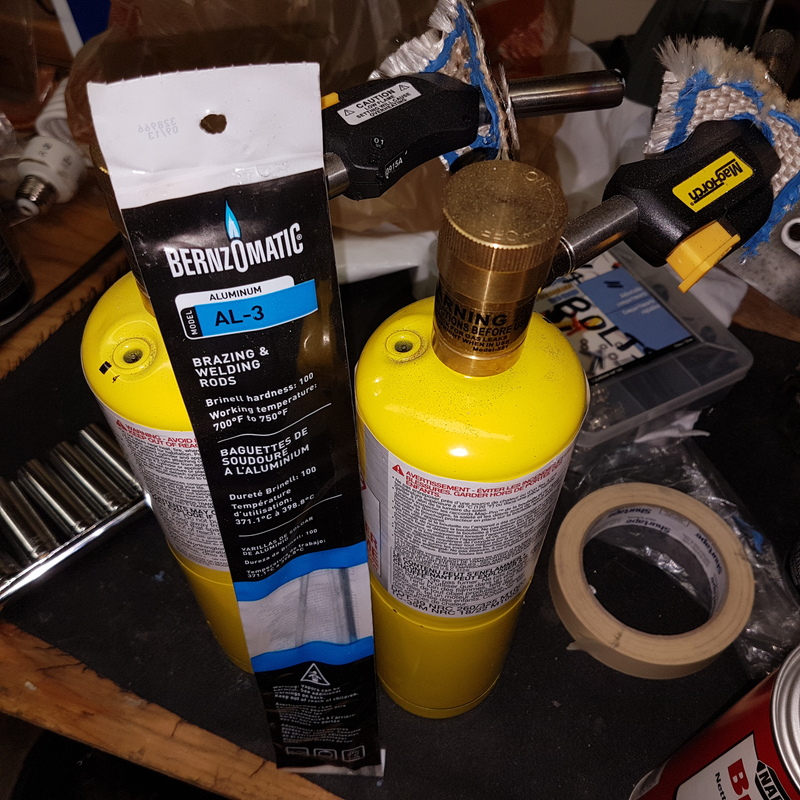
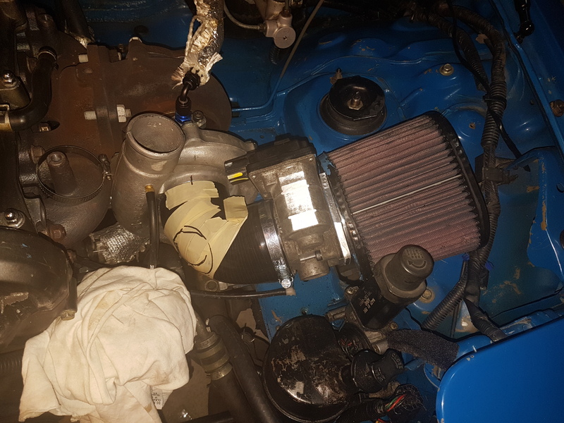
At times the turbo sounded like it needed a larger blow off valve, so I purchased a new unit from a BRZ owner who put on a turbo and claimed they sent him 2 valves. I used aluminum brazing rod to attach this to the turbo outlet pipe.
The silicone 90D hose coming out of the turbo was hitting the hood, so I replaced it with a 2” tight radius aluminum cast elbow. Again I used the aluminum brazing rod but, needed to buy a second torch to get the necessary heat into the compressor housing.
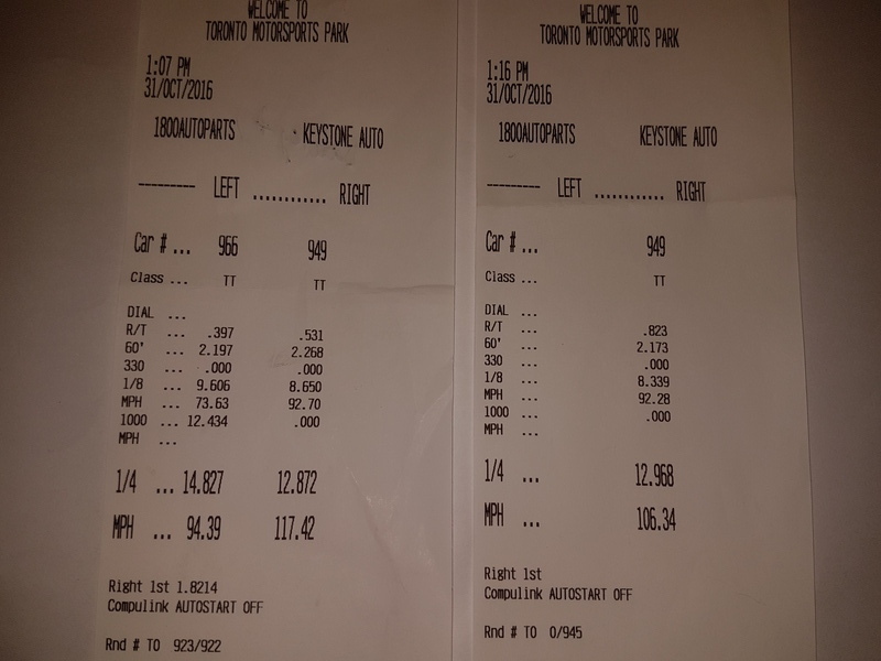
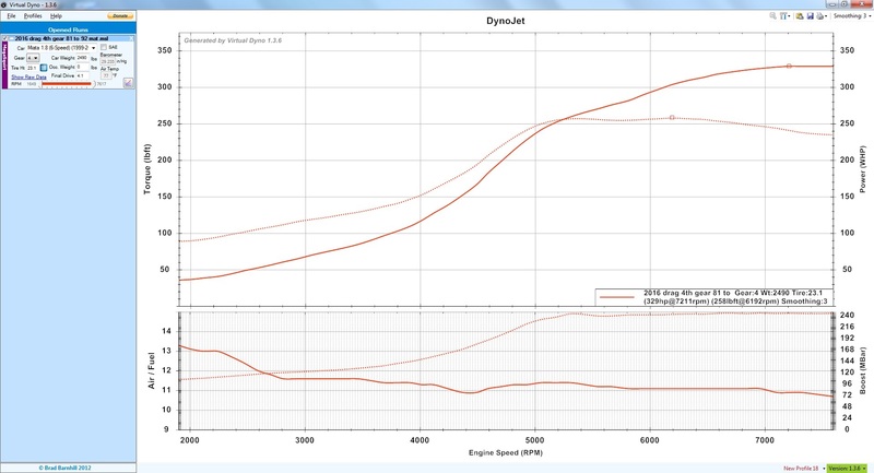
At the end of the season, the car was running fairly well at 21psi, so I went to the drags. Couldn’t get the car to hook up, but did get a better trap speed than I was able to achieve with the supercharger (117 vs 109). Actually the day was full of fail, as I repeatably hit the rev limiter and on occasion shifted from 2nd to 5th.
There was a Honda hybrid at the drags!
Ran a 4th gear pull while at the drags, to get a data log for virtual dyno, on known flat ground. I have quite a bit of work to do, in order to hit my target high end power with the supercharger sucking about 20hp (estimated) at 7000RPM. Spool hurters: Honda intake manifold, 2.5” exhaust, China cast exhaust manifold, Big sleeve bearing turbo. Power hurters:2.5” exhaust, China cast exhaust manifold Here is my timing map (94 octane pump)
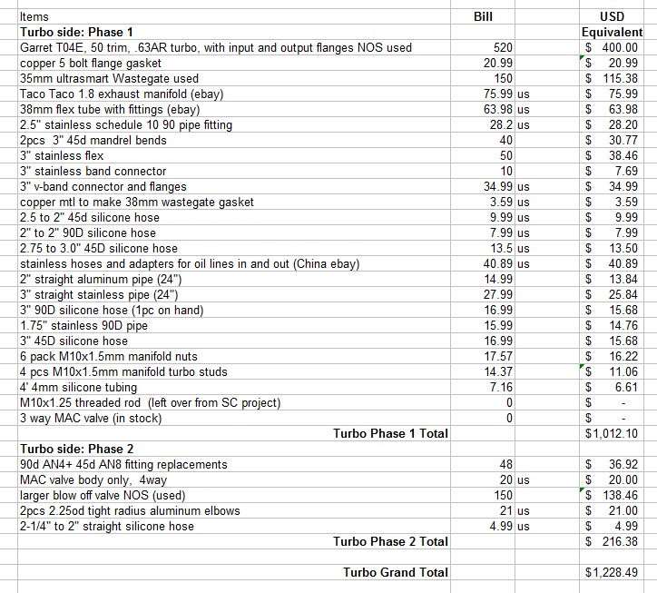
I must have been delusional in thinking this entire project could be done for just $2k.Just for the turbo I am already at 1.2K
Aluminum Brazing:In the past, I have tried a number of Brazing rods for aluminum. Frankly, I have been disappointed with them all.Usually they are very difficult to use, and require special technique to achieve acceptable results. I am very happy to say that this rod changes everything.It is like soldering.Yes, that easy. Only thing, is that it does not flow into a joint like solder. To resolve that, I would apply the filler rod to both pieces first, and then mate them and apply heat. Then use more filler rod to smooth out the joint. (Check out youtube for videos) Rod = Benzomatic AL-3 (but other companies make this too) (Apparently the plastic on these torches can melt, which is why I have the heat shielding on both torches)
Note that many of the parts that are on the upcoming pages were built in stages, in some cases over several months. Rather than keep this chronological, I decided to cover each part from start to finish in one post. Due to this, you will notice discontinuity in some of the photos.
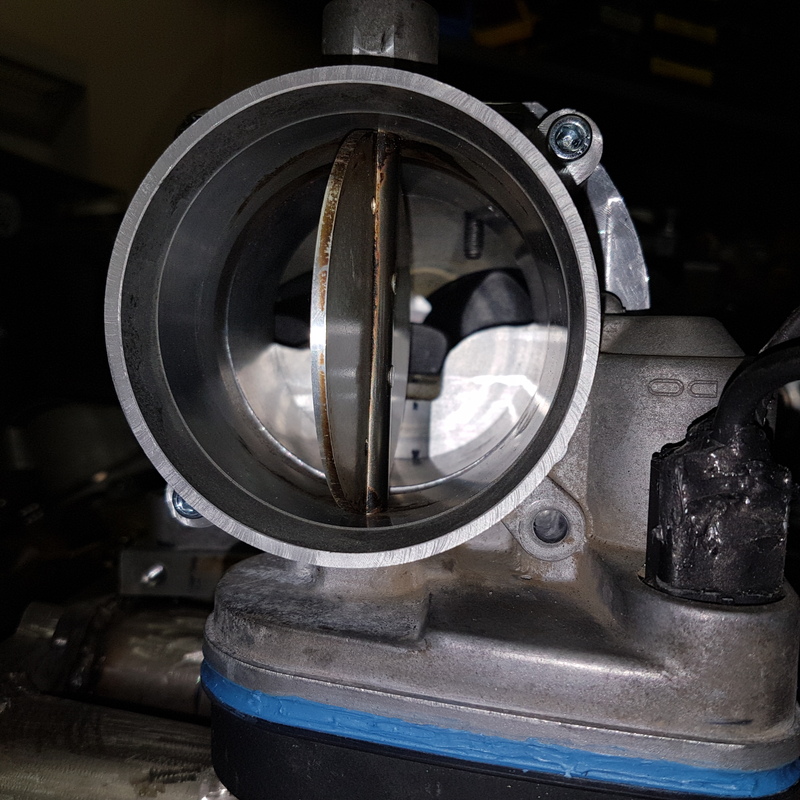
So this build will have 2 electronic throttle bodies in it. One at the inlet to the supercharger, and one at the inlet of the turbo, on a Y pipe.The one connected to the Y pipe, will have just 2 positions, open or closed.
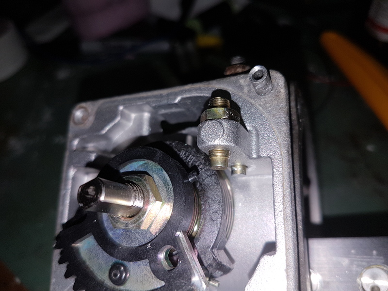
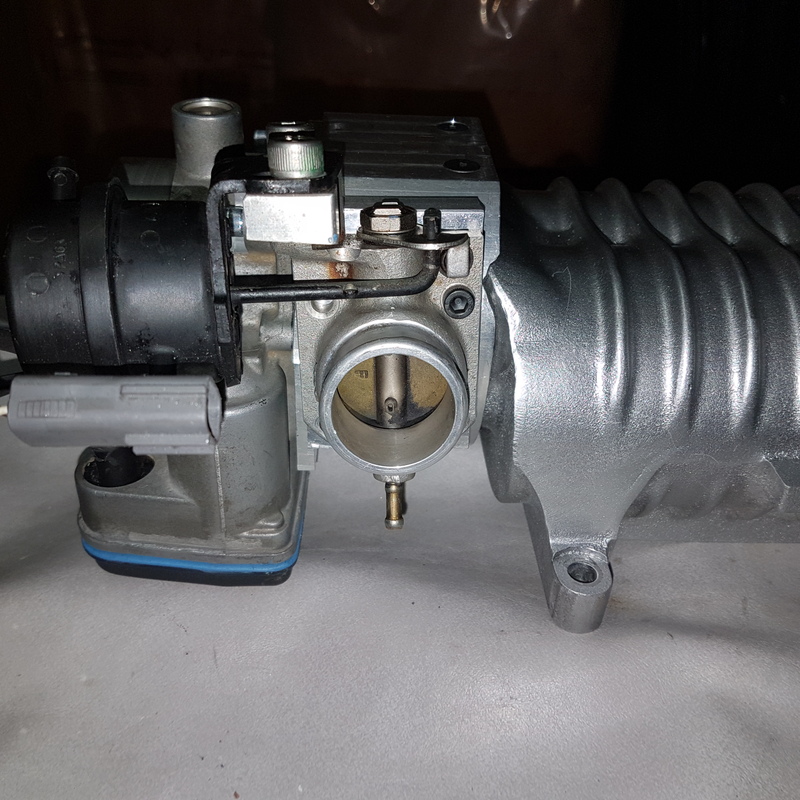
These ETB’s usually have a return spring in them, which returns them to a nearly closed position (they remain partially open, to support limp home mode if there is a failure). One ETB, for the Maxima, has a set screw on the outside of the throttle body which would allow you to change the return position to fully closed. This, and the fact that this throttle inlet pipe is just a hair over 3” made it perfect for this application.
After picking up one of these from a local wrecker, I found that this adjustment screw was seized. So had to take it apart, and grind down the lower post (upper post sets full throttle position).This all worked out ok, it just took longer than expected.
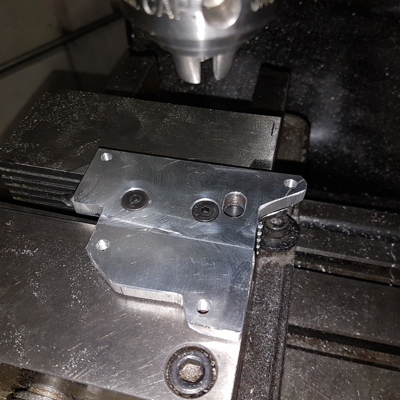
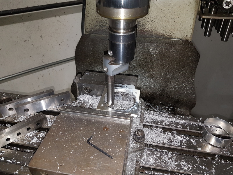
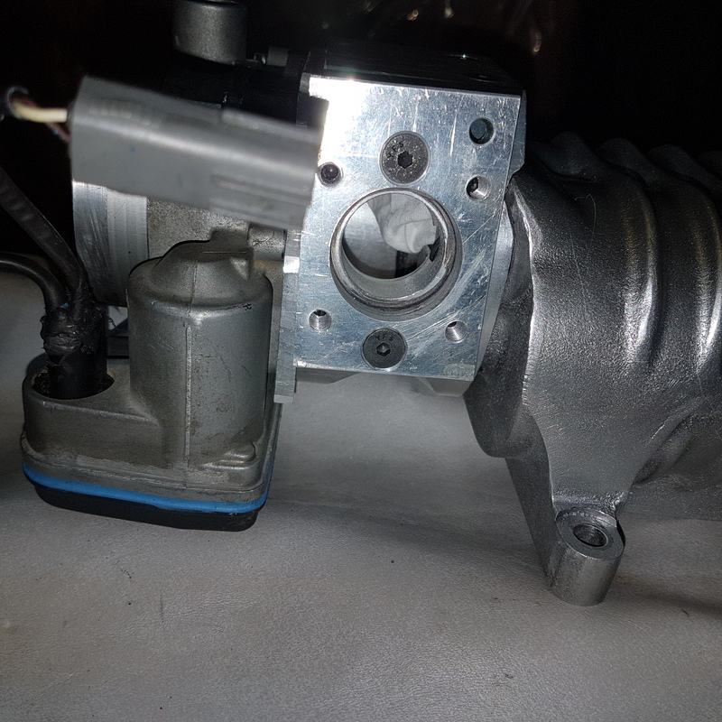
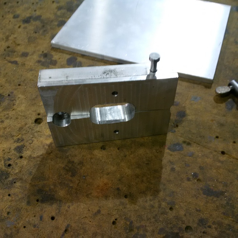
I needed both ends of this throttle body to connect to silicone hoses, so I machined up a plate to attach to the end of the ETB that would normally attach to the manifold.
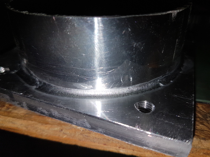
I need to attach this plate to a short piece of 3” pipe, so brazed it.Here is a close up of the brazed seam between the plate and the aluminum pipe.
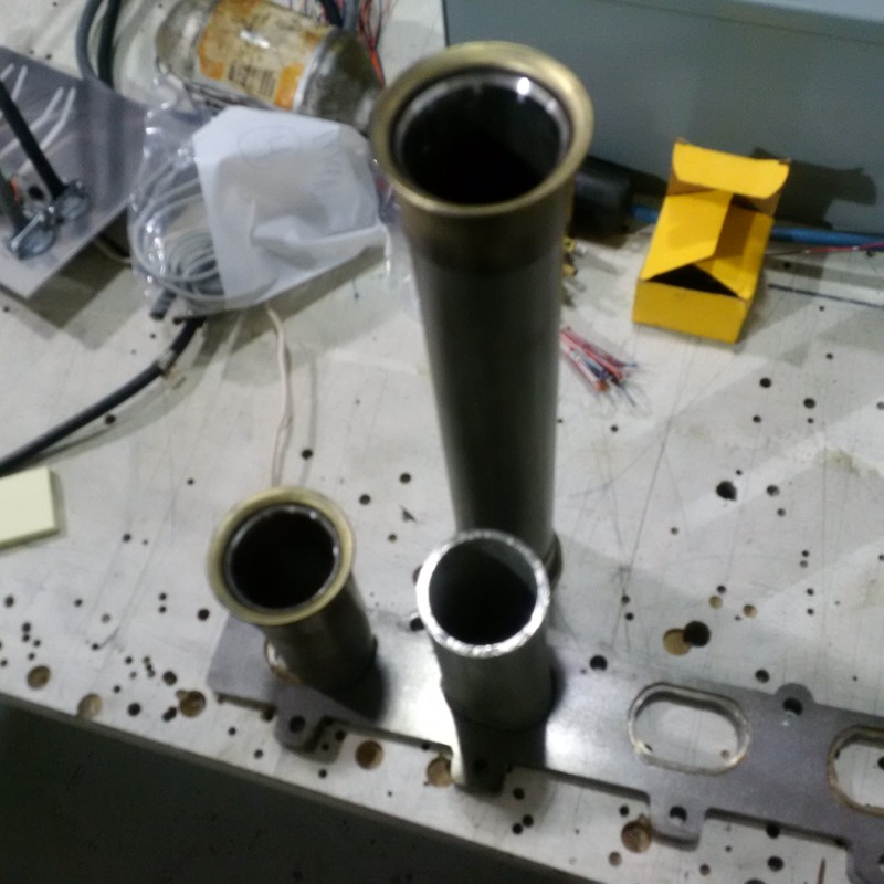
Size comparison of the Volvo valve compared to the Maxima valve. Remember that the Maxima valve can be in any orientation/position which makes it much easier to fit under the hood.
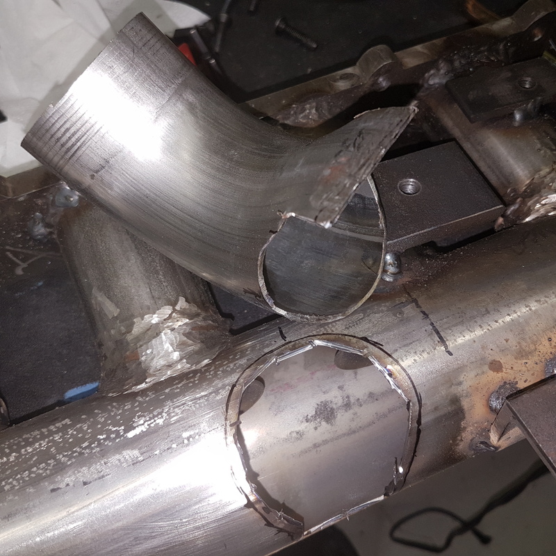
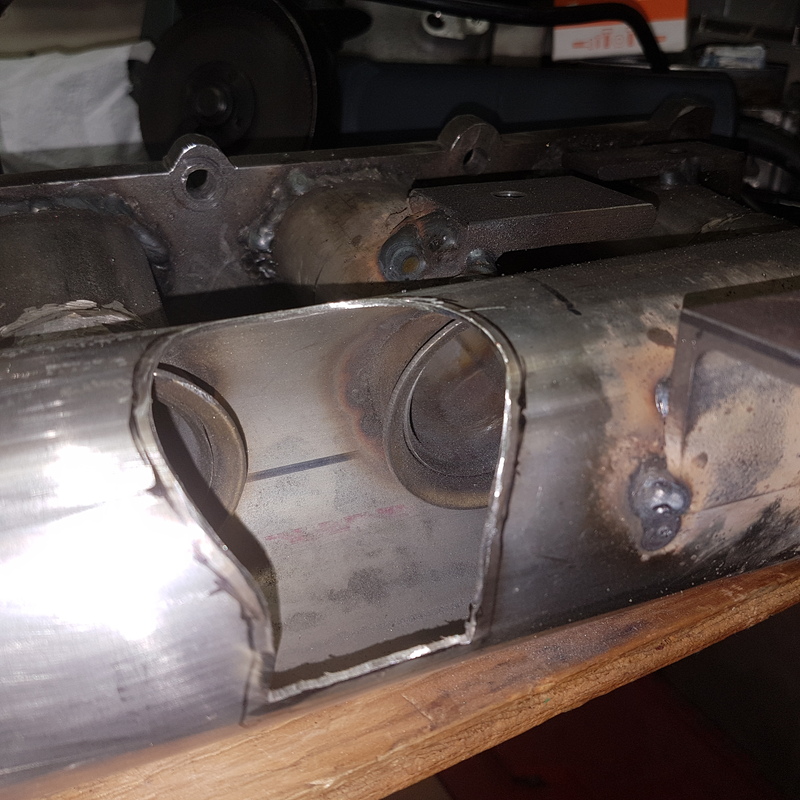
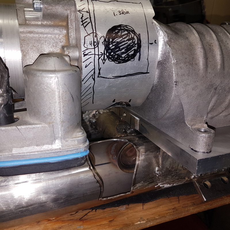
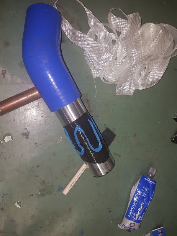
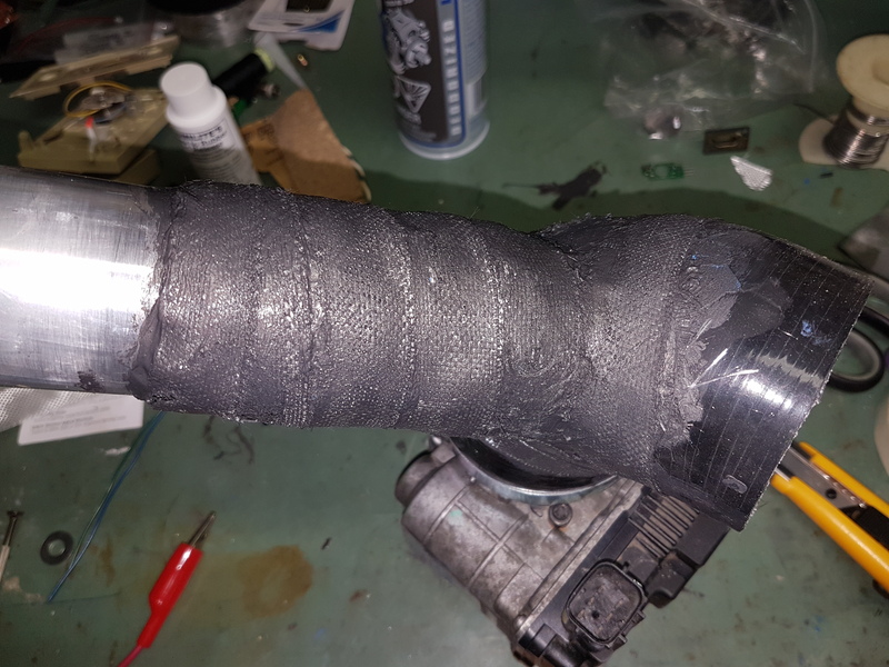
So next I needed a Y pipe to connect the supercharger outlet to the inlet of the turbo, and the above valve. I initially looked around on ebay and such, looking for something that would work, but after I got the turbo installed, I realized that I would need to make something. The space was tight, so I decided to just modify a silicone coupler.I have modified couplers before, but not to this extent.Marking the cutting location on 3” 90D elbow So I started off the hose, with a base of black silicone fusing tape, followed by layers of fibreglass tape and bonding silicone
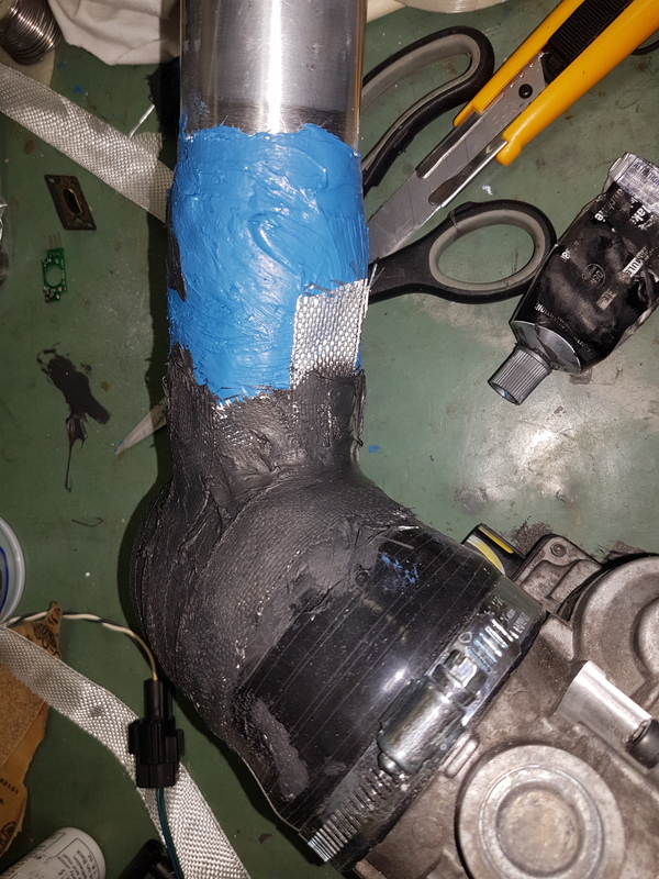
and finally another layer of black silicone fusing tape. I built it on an aluminum pipe with oil on it, so the manufactured hose would not stick to the pipe.I really like the Permatex silicone gasket maker.
.
When you put a layer of silicone on the hose, and then wrap it with the fibreglass, the silicone permeates the fibreglass, creating a strong material.
After building this up to this point, I found that the silicone fusing tape really didn’t want to let go of the aluminum pipe, so decided to build the pipe right into the unit.
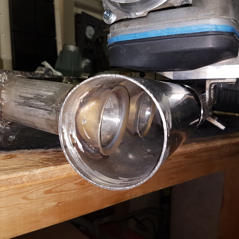
Completed Y pipe After a bit of paint to make things look finished.
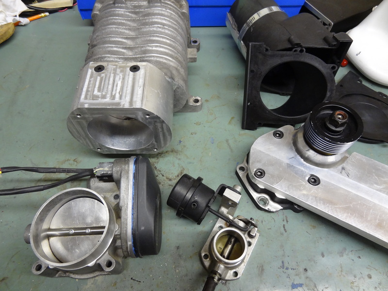
I didn’t take long for me to select the supercharger I wanted to use.Since the supercharger was going to “freewheel” at high RPM, I couldn’t use a screw type that compresses the air, because it would have high parasitic losses. That really left the roots, and I knew I could get pretty good results with a MP62. I was planning on building an intake manifold, and then having a plate which the supercharger would mount to, so I really wanted to have a supercharger designed to bolt to a manifold. There had to be plenty on the used market, and if they were reasonably priced it would be a bonus.
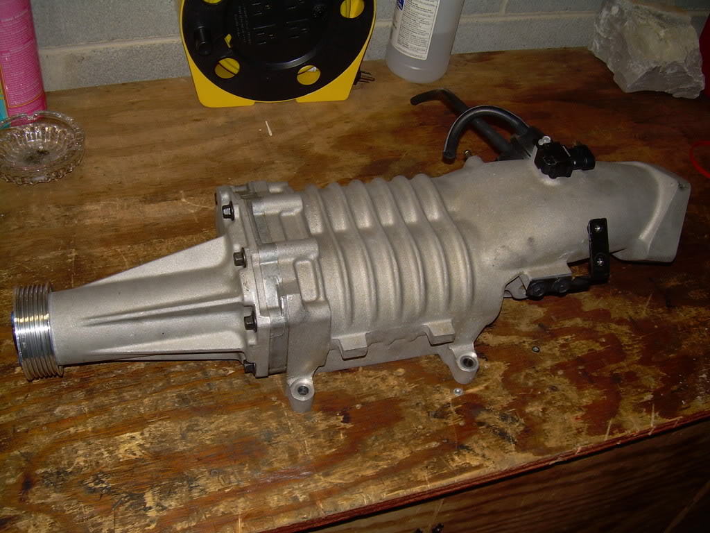
The cobalt supercharger, found on 2005 vintage vehicles met these criteria, however the unit itself was a bit long. The front of the supercharger was not a problem, because someone in my club gave me the nose off a BRP supercharger that had failed (Thanks Dave).This left the rear of the charger. I decided to buy one to see what could be done.Right now, these chargers in my area on Car-Part.com (a site for searching wreckers for parts including pricing) are under $200us,
with ~70k miles on them. Stock internet picture of a Cobalt Supercharger
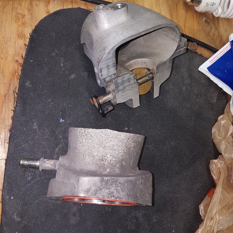
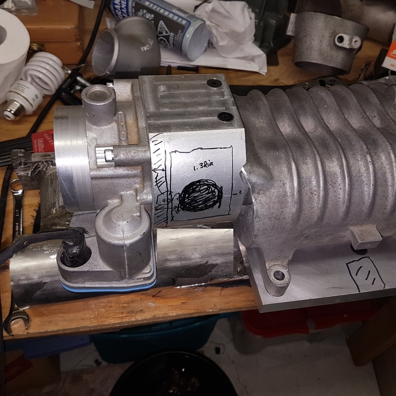
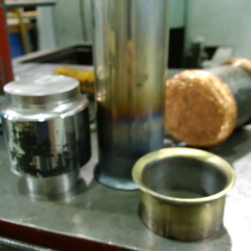
First thing I did after getting and inspecting the charger, was cut 3” off the intake end. I thought I would be able to get that to barely fit into the available space, but I couldn’t figure out how I would connect the bypass valve, which comes out the bottom of the supercharger.
Since I still had the separate bypass valve I used in the M90 project, I decided to cut a further 3” off, removing the bypass valve, which left about .8” of overhang, past the rear bearings on the supercharger.
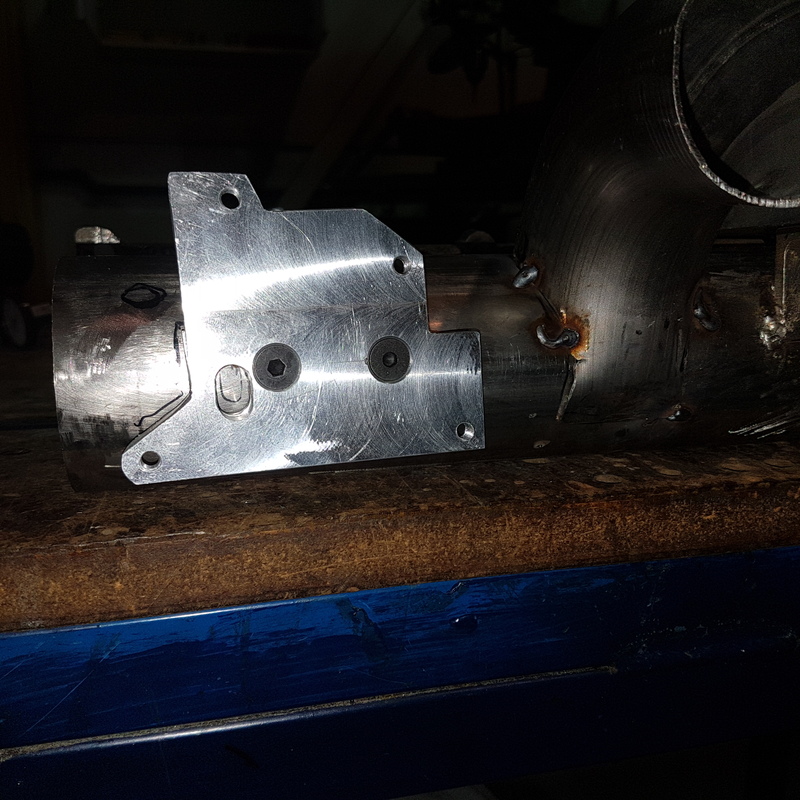
I needed to make an adapter, to connect from this cut off end, to the throttle body.
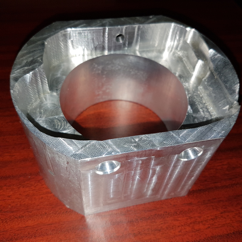
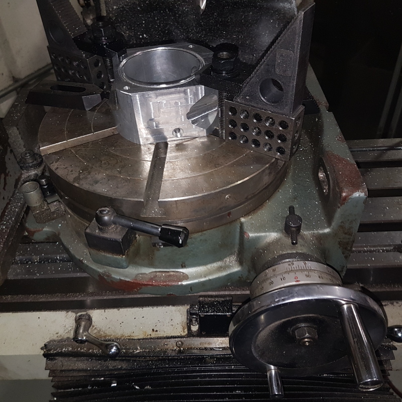
I was fortunate to source a piece of cored aluminum tubing5.125”od, 3.25”id, 2.75” long on EBAY, which I modified to fit over the end of the supercharger. I did have to do some minor modifications to this area on the supercharger, and I filled in the area between the 2 rear bearings with epoxy steel, but figured if this supercharger failed, I could modify a second unit in a reasonable time with hand tools.
I drilled and tapped 3 holes for screws, but the main thing that would be holding this together would be silicone.
By the end of the summer, I had this adapter, as well as the tensioner started, and had reduced the size of the bypass valveand a Chrysler 80mm ETB that I had from an earlier project.
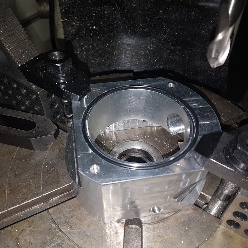
After locking down a number of other items, I had determined where the bypass valve would go, and how much I could shave off the aluminum adapter
Machining a slot for the o-ring gasket.
Hmm, doesn’t exactly flow nicely from the throttle body into the supercharger.Maybe that is a project for next year.
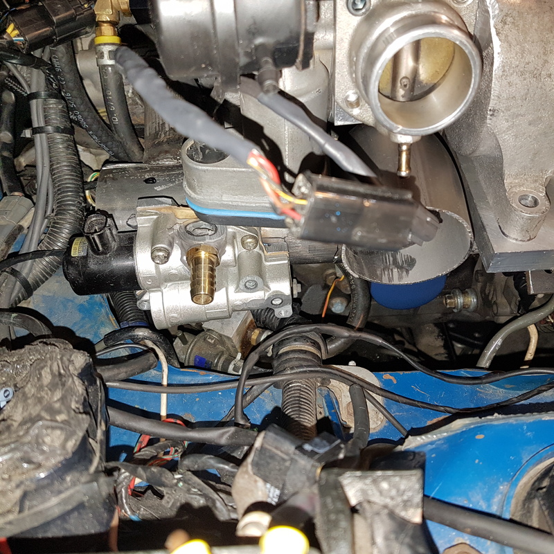
Bypass valve location (also, notice I had to add back in a Ľ” spacer to the throttle body due to clearance issues)
With valve installed (ok 1 screw)
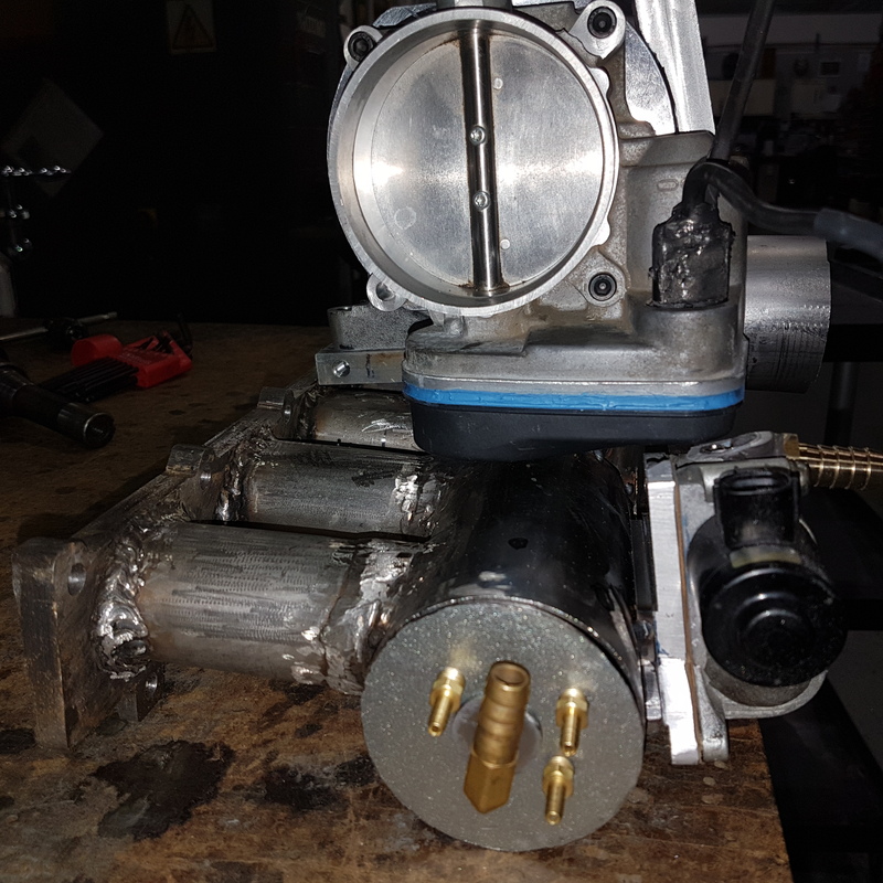
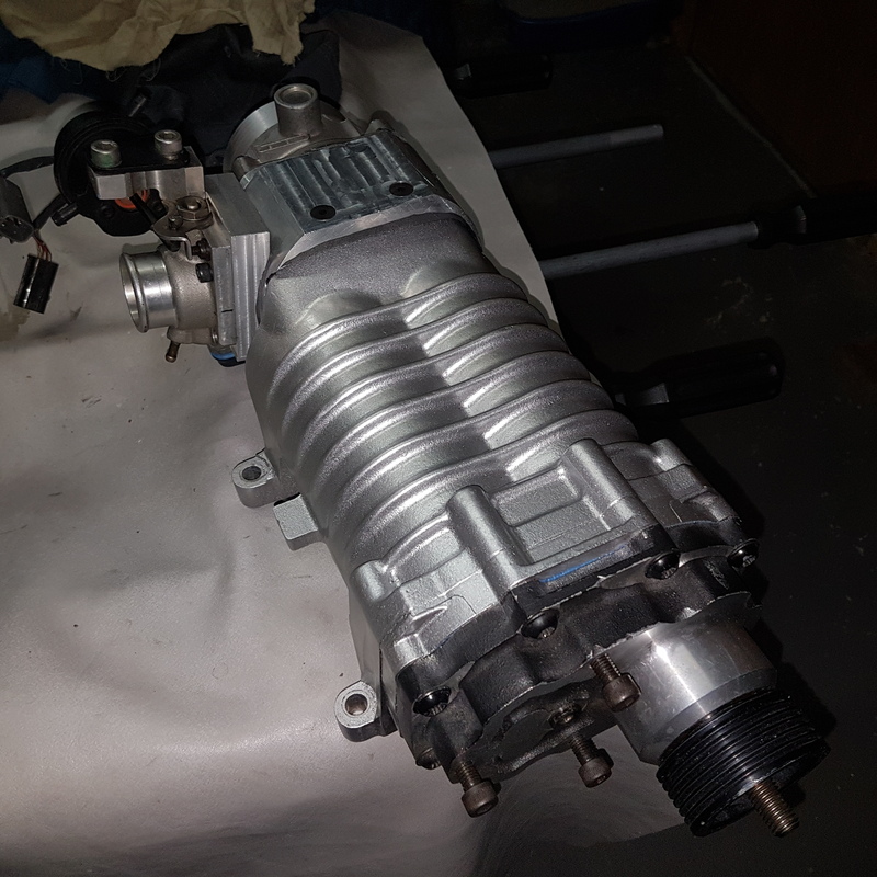
Supercharger, pretty much ready for installation
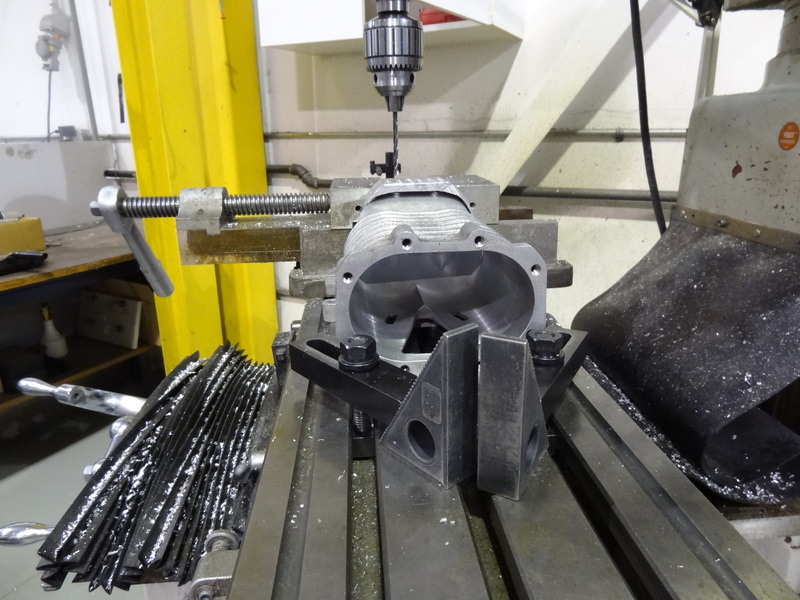
So I ran into an issue with the 4 bolts which mount the supercharger to the base plate. Experience has taught me to always try to pack things in when you are not sure how things are going to ultimately fit.
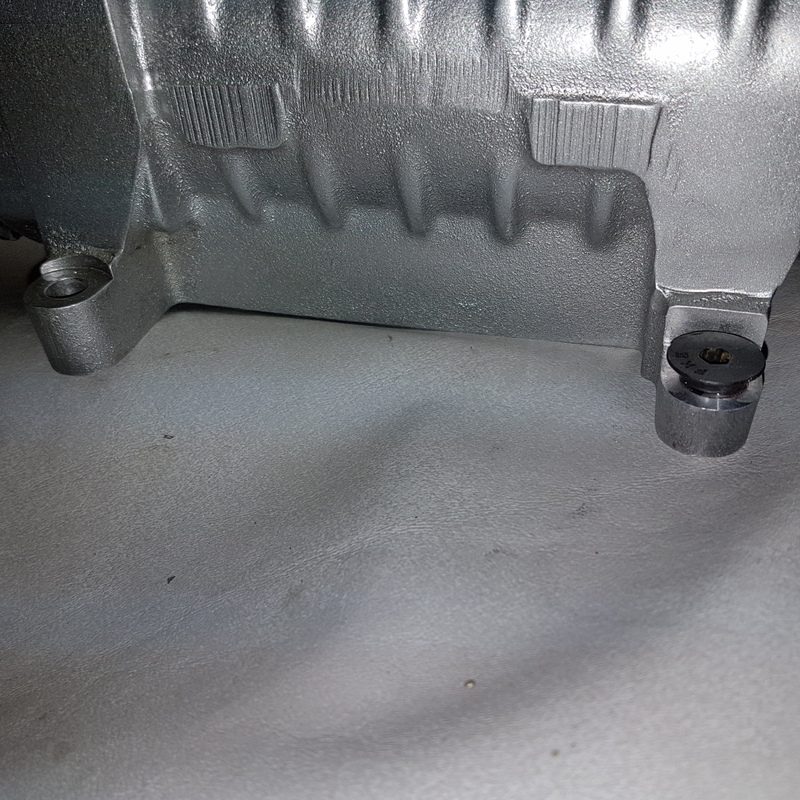
I decided to position the supercharger as close to the engine as possible (which turned out to be the right decision), however half way through, I discovered that I would not be able to get a wrench onto the bolt at the rear of the supercharger, closest to the engine due to interference with the injectors.
This was rather late in the game, so I decided to machine down the leg the bolt goes through and tap it for a steel threaded insert. I will make a small L shaped plate which will attach to this spot, and a future mounting boss that I will put on the manifold plate.
So much for having a mostly stock supercharger that would be easy to swap with a replacement..
I picked up a 150mm crank pulley from FFS and a 62.5mm SC pulley from a local Miata owner. I will re-use the tensioner used in my last build, and fabricate a tensioner bracket when I know what I need.
I still need to figure out how to get cold air to the inlet of the supercharger, but most of the heavy lifting on this assembly is complete.
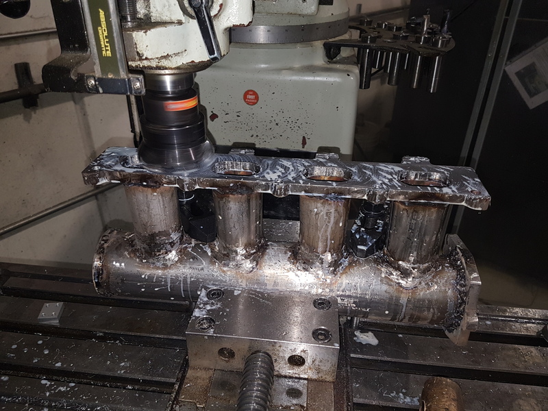
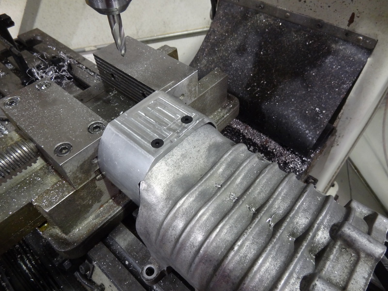
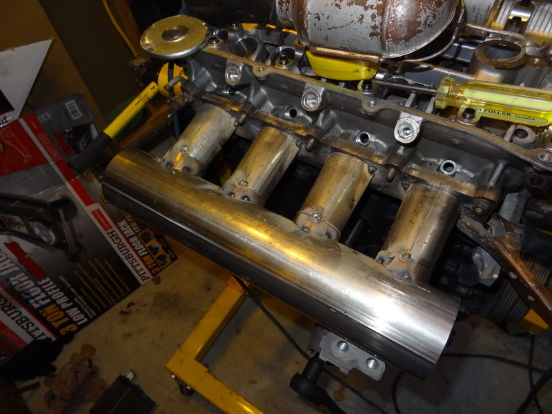
So also during the summer, I started working on the intake manifold. I measured where I thought things would go, under the hood, and then used a spare head to do the details. Since this manifold would also be supporting the supercharger, and I don’t have access to aluminum welding equipment, I decided to make it out of stainless. I did build a header earlier out of stainless, and although it was a pain it was something I was familiar with. So I ordered some schedule 40 tubing for the runners as well as some standard thickness material for the other parts.
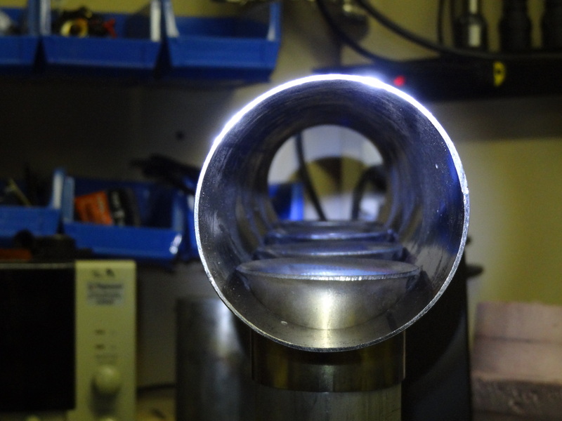
First up was trying to flute the runners.I made a mandrel with the intention of heating up the stainless and pounding it with a hammer. I intended on doing this with the schedule 40 material, but that was impossible! I could not bend the material. So I ended up bending some standard thickness stainless, and then machining the schedule 40 material slightly so the thinner material would slide over. I then bevelled the end of the schedule 40 material, so the air flow would be somewhat “normal”
Sorry for the focus on this one (mandrel on LHS, bent piece on right)
I bent the end of the schedule 40 tubing that goes into the manifold flange with this, in a hydraulic press.
Internal manifold pic Not sure I fluted the ends enough, however probably better than nothing.
After tack welding
I was mig welding this with the incorrect gas, which is one reason why the welds look horrible. The other reason is, well my welding skills are not very refined .I realize that welding with the wrong gas can cause everything from stress cracking to rusting,
however I didn’t suffer any consequences on the header, so am assuming thingswill work out.
Machining the flange flat.
The runner length on this manifold is probably well suited for an engine that turns 13000 rpm, however it’s main purposeis to support the supercharger
and not take up much room, so this was a compromise I had to take.
Time to try it out!Well, I was assuming that I would be mounting the throttle body somewhere near the front of the intake manifoldand I was hoping the IAC
would be on the bottom of the throttle body (the normal spot),but after positioning the supercharger, I realized there was no place for the throttle body
anywhere near I thought it would go.
So I cut off the tack welded on throttle body flange, and considered my options.
This is how I expect the turbo to spool with the supercharger sharing the work.
For this example, let’s assume that the supercharger is geared to produce 15psi of manifold boost, and the electronic waste-gate control on the turbo is controlled to 22psi of manifold boost maximum.
Let’s consider what will happen with regard to boost measurements from 2 locations.
“Manifold boost”, which is the boost pressure at the inlet of the engine, and is used to calculate required fuel, and
“supercharger boost”, which is the boost pressure measured at the output of the supercharger (and input to turbo).
You will notice in the diagram, that both these boost pressures are being monitored by the MS computer.
Operation
At 2000rpm while cruising, you suddenly floor it. ETB2 is closed.
The turbo is barely rotating, and suddenly the supercharger is providing a bunch of air.
The “manifold boost” will now be 15psi, and depending on the restriction the impeller of the turbocharger is making, the “supercharger boost” will be slightly higher (guessing 15-17psi)
At 3000rpm, some time has passed and the turbo is starting to spool.
Let’s suppose that it is doing half of the work. The “manifold boost” will still be 15psi, and “supercharger boost” will be 7.5psi. ETB2 is closed.
At 3900rpm, the turbo is still not fully spooled, but is moving the same amount of air that the supercharger is moving.
The “manifold boost” will now still be 15psi, and “supercharger boost” will be 0psi.
ETB2 is closed.
At 4000rpm, the turbo is still not fully spooled, but wants to generate 16psi of “manifold boost”.
It is sucking more air that the supercharger can provide at 0psi output, so the “supercharger boost” is now -1psi.
ETB2 now needs to be opened, and air from second inlet is introduced which allows "manifold boost" to go to 16psi.
Not entirely sure what will be measured at the "manifold boost" point when ETB2 is still closed and the turbo is trying to pull this extra air.
I expect that the turbo will be able to exceed the 15psi that the supercharger normally provides, but not sure by how much.
At 4300rpm the turbo is fully spooled at 22psi, and ETB needs to remain open until an upshift or throttle off.
The supercharger is always moving air, but above 4000rpm in the above example, it is really like an inefficient fan, moving air from one spot to another.
It will use a lot less power when in this mode though.
So in order to control ETB2, the electronics needs to monitor.
“Supercharger Boost”
“Manifold boost”
“clutch in/out”
some of the electronic logic will probably be.
If clutch is in, then ETB2=closed
If “Manifold boost”>16psi, then ETB2=open
maybe
if “supercharger boost” <0psi and “manifold boost”>16psi, then ETB2=open (with hysteresis on the “supercharger boost” input.
This will require some experimentation, once things are together.
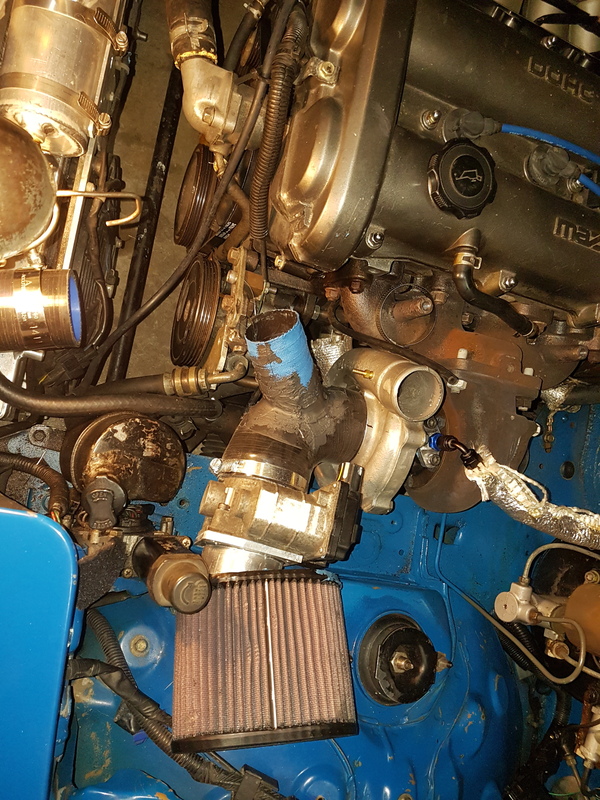
There were not a lot of options for an inlet to the intake manifold. I considered adding another tapered plenum in parallel with the main plenum, but that would interfere with the manifold support arm and looked like a lot of work. I considered coming off the bottom of the manifold and having the throttle body somewhere there, but that was just too impractical. I ended up using a tight radius stainless bend, between the supercharger and throttle body.
It just barely fit!
Also needed to find a new home for the IAC valve. I decided to use the stock 94 valve, and reused a plate I had made for the honda manifold.
Had to reposition the hose connection. Used JB weld to seal the top.
Whoaaaaaaaa what a sweat read. I'm totally subscribing to this one.
Thanks man!
Still quite a bit of work to do, and I really need to get this on the road my mid April.
If I can do that it would give me a full month to debug this before any events.
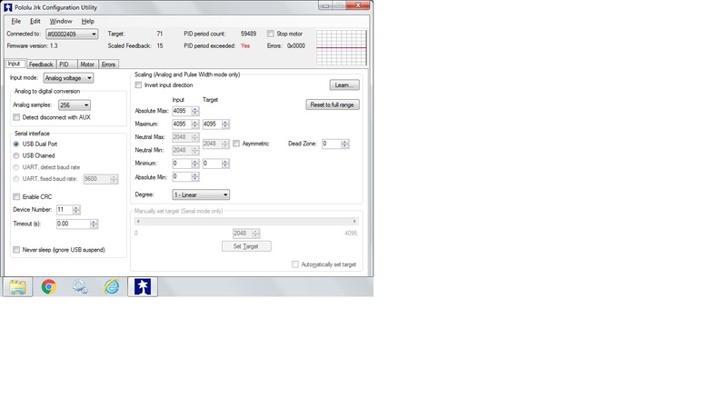
Connecting and controlling an ETB (Electronic throttle body) If you’re working on a project and need an electronic valve or throttle body, automotive electronic throttle bodies are not difficult to control.
Here are the steps: 1.Purchase a throttle body of the correct size. 2.If the throttle body has a return spring, open up the housing, and cut it out.(I use a dremel and a grinding wheel,
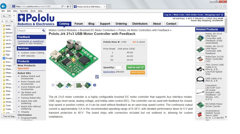
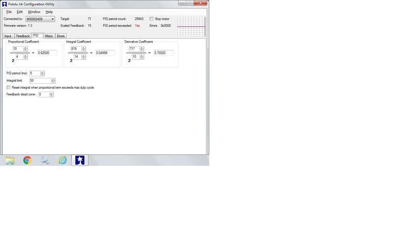
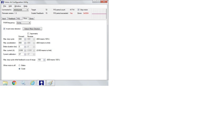
since space is limited and the spring is like an oversized clock spring). 3.Buy a JRK21v3 brushed motor controller 4.Connect it as shown below 5.Download software, and connect USB cable. 6.Set variables as shown below in shots 1-4 7.Read the website so you have an idea of what the JRK is capable of. 8. Power it up with a low voltage (5v), since you may have the polarity on the motor, or the feedback backwards. 9.Correct the polarity in software, and then calibrate the feedback loop (same as you would for the TPS on MS1-3) 10.Have fun!
The throttle body has 2 feedback wipers (for redundancy).You only need 1. You need 5 wires going to the throttle body, 2 wires for power, and 2 wires for control voltage input(0-5v).
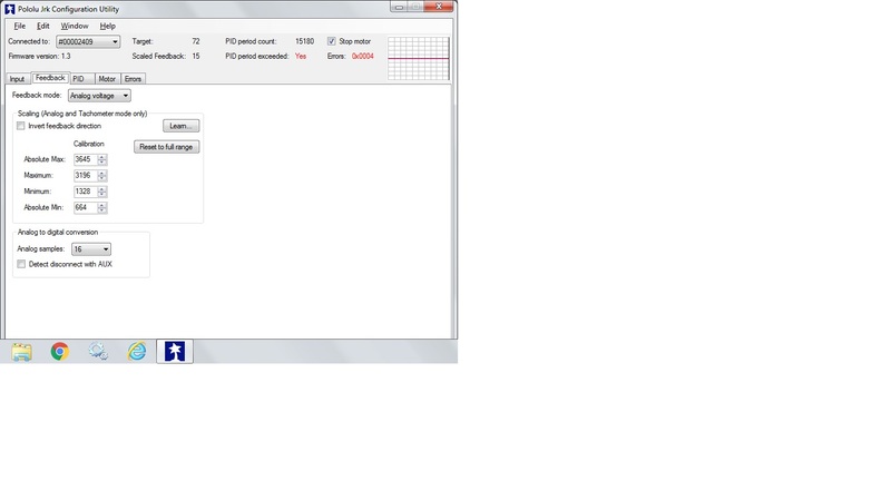
This page is for selecting the feedback signal type.You need to use analog. Learn function allows you to program the fully closed and open positions of the throttle body.
The scaling is programmable , see the learn function, and the output does not have to be linear (but you probably want it that way.)
I have used these PID settings for 3 different throttle bodies with good success.
Set everything to max on this screen, including current.(current is limited inside the IC to 5A)
 02-26-2017, 09:17 PM


 2
2


 .I realize that welding with the wrong gas can cause everything from stress cracking to rusting,