Winter Turbo Build - Custom Equal Length Tial V-band Goodness!
 12-08-2011, 11:55 PM
#41
Elite Member

iTrader: (9)
Join Date: Jun 2006
Location: Chesterfield, NJ
Posts: 6,893
Total Cats: 399
More 
Add a brace to the end of your EWG dump if you plan on leaving it VTA. If you plan on blending it (and maybe even if you plan on VTA), add a flex in there. Vibrant makes a nice smoothliner 1.5" pipe, short flex. It's a lot nicer than others. There's a few others making them that I saw at PRI but vibrant is easy to deal with typically. Also, vibrant makes a super dooper tight radius 1.5" Ubends that may make your EWG routing/life more enjoyable.
Add a brace to the end of your EWG dump if you plan on leaving it VTA. If you plan on blending it (and maybe even if you plan on VTA), add a flex in there. Vibrant makes a nice smoothliner 1.5" pipe, short flex. It's a lot nicer than others. There's a few others making them that I saw at PRI but vibrant is easy to deal with typically. Also, vibrant makes a super dooper tight radius 1.5" Ubends that may make your EWG routing/life more enjoyable.

Reply
 0
0

0
12-08-2011, 11:57 PM
#42
Junior Member
Thread Starter
iTrader: (2)

Join Date: Jul 2011
Location: Grand Rapids, MI
Posts: 213
Total Cats: 48
This is the first I've seen this thread, excellent job. I am impressed. It makes my stuff look ghetto!
-Polishing those weld elbows must have taken an incredible amount of time. I can't fathom that. Just taking them to the wire wheel takes too long.
-Very nice weld fixture.
-I am also impressed you were able to cut the collector with a chop saw (my tool of choice cause i'm impatient). I never tried, but in my mine it wasn't possible while keeping your fingers or not scrapping a lot of material. I use a horizontal band saw and tack the pipe to a fixture. I do the first cut on each of the 4 pipes, tack pairs together, cut the second cut on each pair, then tack together the full collector, cause the angle from one cut to the other on each indivitual pipe isn't the same for my collectors (i.e. the axis of each pipe does not point to the same spot within the flange).
-I am glad to see the use of Solidworks and an explaination of it's use, along with your full process. I'm glad I'm not the only one whipping up wooden mockups first.
I have tried to model manifolds within solidworks a few different ways, but my current method is perhaps slightly different than yours. I do not have much experience defining parts within an assembly; not sure why, but it's a pet pieve of mine. Perhaps cause a co-worker does it daily, then explodes the relations and fixes everything so you can't ever modify anything easily. Anyway...I will have to try your method, it may be easier.
With the exception of the flanges, my manifolds are modeled within a single part file using individual 3D sketches for each primary pipe path, starting at a sketch that is the head flange geometry (which also doubles as the cross section sketch for the swept 'feature'/pipe) and ending at the entry location of the collector. Within each individual primary pipe's 3D path sketch are however many 2D sketch planes needed (I try to limit it to 3 or 4) to define the path within the confines of whatever weld elbow geometry you have available (i.e. 2.25" and 1.5" radii for 1.5" pipe). Therefore I often do use greater angles than 90deg. Pipes and straights that are tangent to each other and can be constrained/defined within a 2D plane (the 2D sketch planes in this case) are done so, and the angles between each 2D sketch plane or sketch plane and the datum define the pipe's shape. Again, this is done within the individual 3D sketch of each primary tube. Once each primary path is done, I sweep the cross section and the rest is easy. So far I use only 1 collector because, for me, it was a PITA and confusing to get the angles out of it for the cut fixture.
Wait, what?
It can get real messy, real quick. Solidworks likes to flip the constraints over on you making stuff all sorts of crazy. I save often. It takes a computer more powerful than the one I have at home to do it right but I still manage somehow...i need to find a better way It doesn't help that I have SW2007 at home and 2011 at work, so I can't open work's files at home. I have to try to remember what worked and redo it (with the wife's trackball...ugh). I mean, I can move/rotate/angle the collector flange within it's defined parameters and hit refresh and, within reason, it will update just fine, but ideally I'd like to also be able to grab each primary pipe and drag it real-time. I think using a "flexible" assembly process with individual bend/straight sections may be able to do this...
Are you using all 2.25" radius bends? Christ man, very nice. This has my vote on best flowing equal length mani to date. I had to use some 1.5" radii bends on Lars' to get it 'equal' within .020" theoretically (14.350" OAL), whereas the all 2.25" radii version has 11.750" long 1 & 4 primaries.
Does it clear the hood?
-Polishing those weld elbows must have taken an incredible amount of time. I can't fathom that. Just taking them to the wire wheel takes too long.
-Very nice weld fixture.
-I am also impressed you were able to cut the collector with a chop saw (my tool of choice cause i'm impatient). I never tried, but in my mine it wasn't possible while keeping your fingers or not scrapping a lot of material. I use a horizontal band saw and tack the pipe to a fixture. I do the first cut on each of the 4 pipes, tack pairs together, cut the second cut on each pair, then tack together the full collector, cause the angle from one cut to the other on each indivitual pipe isn't the same for my collectors (i.e. the axis of each pipe does not point to the same spot within the flange).
-I am glad to see the use of Solidworks and an explaination of it's use, along with your full process. I'm glad I'm not the only one whipping up wooden mockups first.
I have tried to model manifolds within solidworks a few different ways, but my current method is perhaps slightly different than yours. I do not have much experience defining parts within an assembly; not sure why, but it's a pet pieve of mine. Perhaps cause a co-worker does it daily, then explodes the relations and fixes everything so you can't ever modify anything easily. Anyway...I will have to try your method, it may be easier.
With the exception of the flanges, my manifolds are modeled within a single part file using individual 3D sketches for each primary pipe path, starting at a sketch that is the head flange geometry (which also doubles as the cross section sketch for the swept 'feature'/pipe) and ending at the entry location of the collector. Within each individual primary pipe's 3D path sketch are however many 2D sketch planes needed (I try to limit it to 3 or 4) to define the path within the confines of whatever weld elbow geometry you have available (i.e. 2.25" and 1.5" radii for 1.5" pipe). Therefore I often do use greater angles than 90deg. Pipes and straights that are tangent to each other and can be constrained/defined within a 2D plane (the 2D sketch planes in this case) are done so, and the angles between each 2D sketch plane or sketch plane and the datum define the pipe's shape. Again, this is done within the individual 3D sketch of each primary tube. Once each primary path is done, I sweep the cross section and the rest is easy. So far I use only 1 collector because, for me, it was a PITA and confusing to get the angles out of it for the cut fixture.
Wait, what?
It can get real messy, real quick. Solidworks likes to flip the constraints over on you making stuff all sorts of crazy. I save often. It takes a computer more powerful than the one I have at home to do it right but I still manage somehow...i need to find a better way
It doesn't help that I have SW2007 at home and 2011 at work, so I can't open work's files at home. I have to try to remember what worked and redo it (with the wife's trackball...ugh). I mean, I can move/rotate/angle the collector flange within it's defined parameters and hit refresh and, within reason, it will update just fine, but ideally I'd like to also be able to grab each primary pipe and drag it real-time. I think using a "flexible" assembly process with individual bend/straight sections may be able to do this...Are you using all 2.25" radius bends? Christ man, very nice. This has my vote on best flowing equal length mani to date. I had to use some 1.5" radii bends on Lars' to get it 'equal' within .020" theoretically (14.350" OAL), whereas the all 2.25" radii version has 11.750" long 1 & 4 primaries.
Does it clear the hood?
http://www.absurdflow.com/miata/acps...mhornequal.jpg
was my inspiration for this manifold. In fact finding your website was what planted the seed in my brain to build my own manifold. I emailed you back in July because I wanted you to build it for me but you said you weren't building anything in the summer months. So it's all your fault
Modeling parts in context is the way to go. In SW 2011 you can even save the parts within the assembly, so you can actually have an assembly of many parts all contained within just one file. I agree that you have to take extra precautions when doing so though - and you have to especially careful when making revisions (careful use of pack-and-go is key). I went through 5 iterations of my design before I started building.
I don't use any planes at all when doing the 3D path sketches - I'm not really sure why you would need to?
Yes I used all long radius 1-1/4" schedule 40 elbows - can't remember the CLR off the top of my head but 2.25" sounds right.
Also you are right about the polishing - probably took about 6-8 hours to sand out and polish everything.
Reply
0
0
12-09-2011, 12:02 AM
#44
Junior Member
Thread Starter
iTrader: (2)
Join Date: Jul 2011
Location: Grand Rapids, MI
Posts: 213
Total Cats: 48
Just received one in the mail yesterday...copied you on that one again...I should start paying you royalties or something...
https://www.miataturbo.net/showpost....1&postcount=30
https://www.miataturbo.net/showpost....1&postcount=30
Reply
0
0
12-09-2011, 12:05 AM
#45
Elite Member
iTrader: (9)
Join Date: Jun 2006
Location: Chesterfield, NJ
Posts: 6,893
Total Cats: 399
BWAahhaha. I edit and edit and edit my posts too. Yep, absurdflow = me. I'm glad I didn't do your mani, you gave me...us all another milestone to aim towards.
There aren't too many CAD guys where I work so I don't have the chance to learn new ways to model from other guys. 99% of my continuing modeling education is accidental or by paging thru solidworks website when I have the time (rarely). It's be cool to work with someone like you.
There aren't too many CAD guys where I work so I don't have the chance to learn new ways to model from other guys. 99% of my continuing modeling education is accidental or by paging thru solidworks website when I have the time (rarely). It's be cool to work with someone like you.
Reply
0
0
12-09-2011, 12:09 AM
#46
Elite Member
iTrader: (9)
Join Date: Jun 2006
Location: Chesterfield, NJ
Posts: 6,893
Total Cats: 399
Just received one in the mail yesterday...copied you on that one again...I should start paying you royalties or something...
https://www.miataturbo.net/showpost....1&postcount=30
https://www.miataturbo.net/showpost....1&postcount=30
Reply
0
0
12-09-2011, 12:18 AM
#47
Junior Member
Thread Starter
iTrader: (2)
Join Date: Jul 2011
Location: Grand Rapids, MI
Posts: 213
Total Cats: 48
BWAahhaha. I edit and edit and edit my posts too. Yep, absurdflow = me. I'm glad I didn't do your mani, you gave me...us all another milestone to aim towards.
There aren't too many CAD guys where I work so I don't have the chance to learn new ways to model from other guys. 99% of my continuing modeling education is accidental or by paging thru solidworks website when I have the time (rarely). It's be cool to work with someone like you.
There aren't too many CAD guys where I work so I don't have the chance to learn new ways to model from other guys. 99% of my continuing modeling education is accidental or by paging thru solidworks website when I have the time (rarely). It's be cool to work with someone like you.
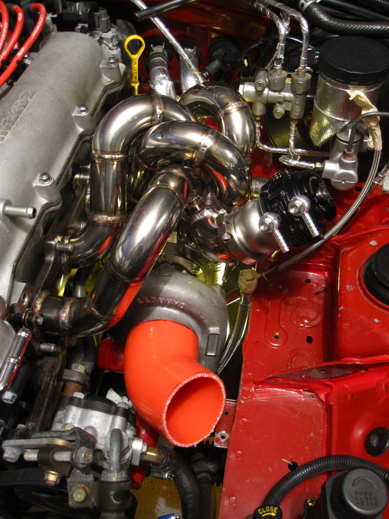
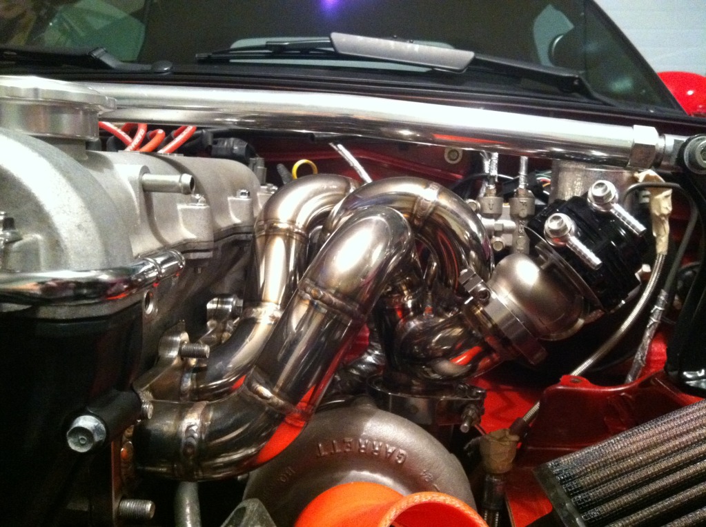
To answer your question, it clears the hood by a mile. If you were to put a straight edge across the lettering on the valve cover and extend it over the manifold, the top of the runners would clear the straight edge by about 3/8". The turbo location I am using it slightly higher than the Absurdflow AC/PS location, so I had to use a suboptimal 23 degree merge angle to save some space - thats really the only compromise in the design.
Reply
1
1
12-09-2011, 12:24 AM
#48
Elite Member
iTrader: (9)
Join Date: Jun 2006
Location: Chesterfield, NJ
Posts: 6,893
Total Cats: 399
 just somewhat kiddin...I've been doing it longer than you, I should know more than I do. Damnit.
To answer your question, it clears the hood by a mile. If you were to put a straight edge across the lettering on the valve cover and extend it over the manifold, the top of the runners would clear the straight edge by about 3/8". The turbo location I am using it slightly higher than the Absurdflow AC/PS location, so I had to use a suboptimal 23 degree merge angle to save some space - thats really the only compromise in the design.
Reply
0
0
12-09-2011, 12:31 AM
#49
Junior Member
Thread Starter
iTrader: (2)
Join Date: Jul 2011
Location: Grand Rapids, MI
Posts: 213
Total Cats: 48
I will send you my SW file - if you pay me royalties on each one you build
....
Reply
0
0
12-09-2011, 10:39 AM
#50
Elite Member
iTrader: (2)

Join Date: May 2007
Location: Cromwell, Connecticut
Posts: 2,604
Total Cats: 16
Turbotim I LOLed at your comment about a Coworker defining parts in an assembly and making constraints blow up and designs impossible to edit. This describes my boss exactly. He will make a 2d skeletal model and relate EVERYTHING back to it. It's a huge mess of irrelevant relationships. Makes me pull my hair put.
Reply
0
0

 ??
12-13-2011, 01:32 PM
??
12-13-2011, 01:32 PM
#52
Junior Member
Thread Starter
iTrader: (2)
Join Date: Jul 2011
Location: Grand Rapids, MI
Posts: 213
Total Cats: 48
Realistically, I would probably have to charge A LOT to make it worth my time.
Talk to Tim at Absurdflow...
Talk to Tim at Absurdflow...
Last edited by mx592; 12-15-2011 at 02:53 PM.
Reply
0
0
 12-13-2011, 04:39 PM
#55
I really want an equal length tubular design manifold for my build. I haven't found one easy to install with AC/PS. I decided to go with Tim's tubular FM replacement, so I contacted him bout it last week. As he said here, he offered to build the manifold but then I had to find someone to build the DP which would have been another issue. I have been in contact with Abe since about his design and he has been very helpful.
But if you are willing to build another one I'm down to pay for your time and wait since I'm in no rush for this build and rather do it once the right way and get what I really want.
But if you are willing to build another one I'm down to pay for your time and wait since I'm in no rush for this build and rather do it once the right way and get what I really want.
Last edited by JDMPalace; 12-14-2011 at 03:09 AM.
Reply
0
0
 12-15-2011, 04:04 PM
#59

Not sure if you would want it, because I know for a fact that the hole locations for the manifold studs are a bit off. They were close enough that the flange I bought from SLS still fit on my assembly jig (there was enough clearance in the hole of the flange to the 3/8" bolts I used, luckily).
Honestly its such a good deal to just buy one from SLS, I don't know if it would be worth your time to write the program and CNC one, even if you had the equipment?
Honestly its such a good deal to just buy one from SLS, I don't know if it would be worth your time to write the program and CNC one, even if you had the equipment?
But thank you for this and pushing some of us to think outside the box and giving us some excellent ideas. Amazing work!!!
Reply
0
0