When you click on links to various merchants on this site and make a purchase, this can result in this site earning a commission. Affiliate programs and affiliations include, but are not limited to, the eBay Partner Network.
Has anyone figured out how to wire in an AEM Failsafe wideband O2/Boost guage to megasquirt?
I thought I figured it out, but when I start my new turbo build I get an obnoxiously high idle and no wideband sensor input (Yes, I started the project with a "wideband" selected)
What I thought I did right:
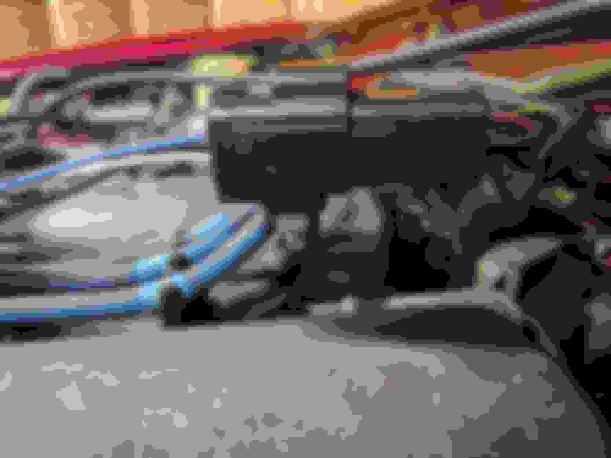
Normal Wideband setup uses the stock 4-wire harness. From an article I found, I read that the O2 signal was the black wire from the sensor, to the blue wire in the stock 02 sensor harness. This was done on a used wideband I bought with the used kit I purchased (So it's gotta be right, right?). See picture. The blue wire space in the harness leads to a red/blue wire on the other side, and goes into the middle of the Pinout for the MS2 (PNP). I verified this with a continuity test: What I spliced into at the ECU harness is what is the R/L at the stock sensor harness.
I used the sensor ground in what I found to be the sensor ground, and grounded the failsafe guage in the ground.
But when I start the car, the MS/Tunerstudio does not register the AFR. I'm hoping this is what is causing my high idle. I did adjust the screw in the throttle body as much as I could, which reduced it about 300 RPM ... What are your thoughts? The only thing I can think of is that the failsafe is actually changing the signal type in some way that the "standard" wideband would not, and therfore the MS cannot accept the reading ... What do you think? Notice 2N is the wideband input; continuity verified with the Red/Blue wire in the stock sensor. Notice the sensor ground, and regular ground 2B and 2D, respectively Blue wire (top closest to camera as shown) goes to the Red/Blue Actual AFR (and pressure in digital display)
(See next post for more pictures and description)
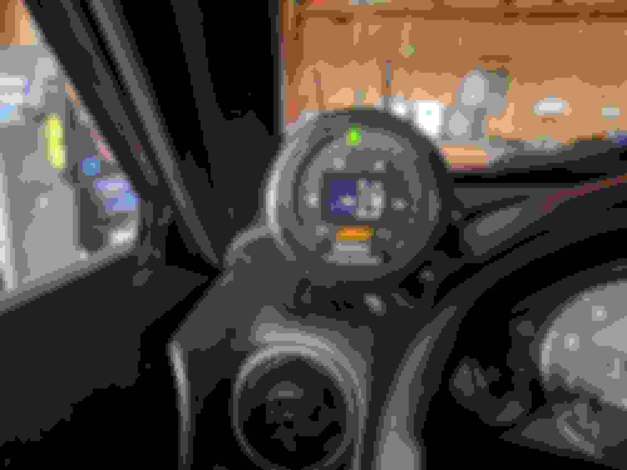
What Tunerstudio sees as Wideband signal ... and note the ridiculous Idle speed... What!??? Failsafe wiring guide - White = AFR output from sensor/guage My home-made splice and solder job (with some cheapo electric tape. The connection is strong - I tugged it to be sure it was holding before taping it. Notice the white goes to space 2N - the Red / Blue wire that is connected to the stock O2 Harness.
I'm really lost on what else to check. What does the wise internet say? On a side note, I thought the 2-in-1 display looks great.
I even plugged in A SEPARATE pnp unit to the miata ... that one didn't read read an AFR either. There is an output from the guage to the ECU that is showing 0-5V based on AFR. I tested on the input side of the ecu harness, so I know the signal is getting to the ECU, but the NEITHER ECU is accepting the signal. I really need some suggestions. Everywhere I've read, I'm using the right input for the ECU to read the wideband signal (2N - a red wire with a blue strip), and it's calibrated correctly in TunerStudio under the tools menu. The ECU is reading approx 0.01V when on the "on" position, but the gauge is outputting 5V. (Found by guess and check with "manual wideband" settings under the calibrate wideband menu).
Are BOTh ECUs messed up in the SAME way? (both ECUs are from different sources).
On a side note, it's still idling at a ridiculous 4k rpm, so any suggestions for that would be great as well. I really could use your help, especially since my wife is giving me the "is this ever getting out of the garage" questions ...


 0
0


