
mikewolf's DIY turbo on an XP miata


Thread Starter
Junior Member
iTrader: (2)
Joined: Oct 2007
Posts: 140
Total Cats: 0
From: Near buffalo
Hi everyone,
I'm getting close to getting the car ready and thought I would show some of my progress.
Everything on the car has been done by my dad and I. The car needs the ms installed and then a trip to the dyno for tuning.
I have very little money in this car (~$2500) mostly as a result of waiting to find deals, making my own parts and selling stuff off the car.
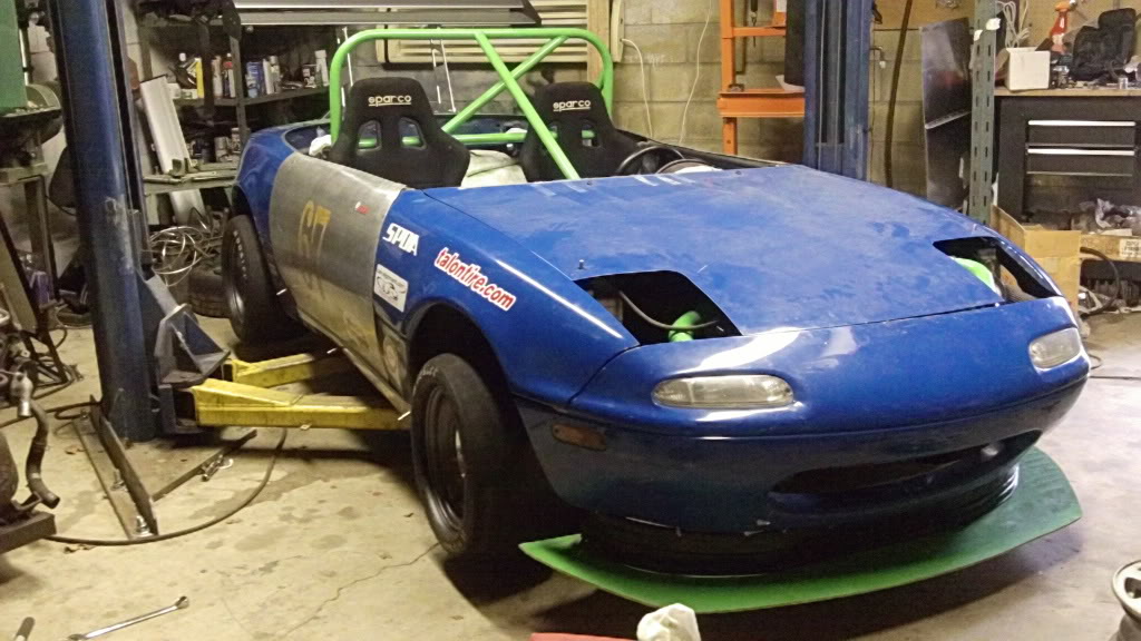
The car is a 90 miata with a stock 1.6. The car has a lot of weight reduction and weighed 1650lbs before the turbo. It still has some more to loose.
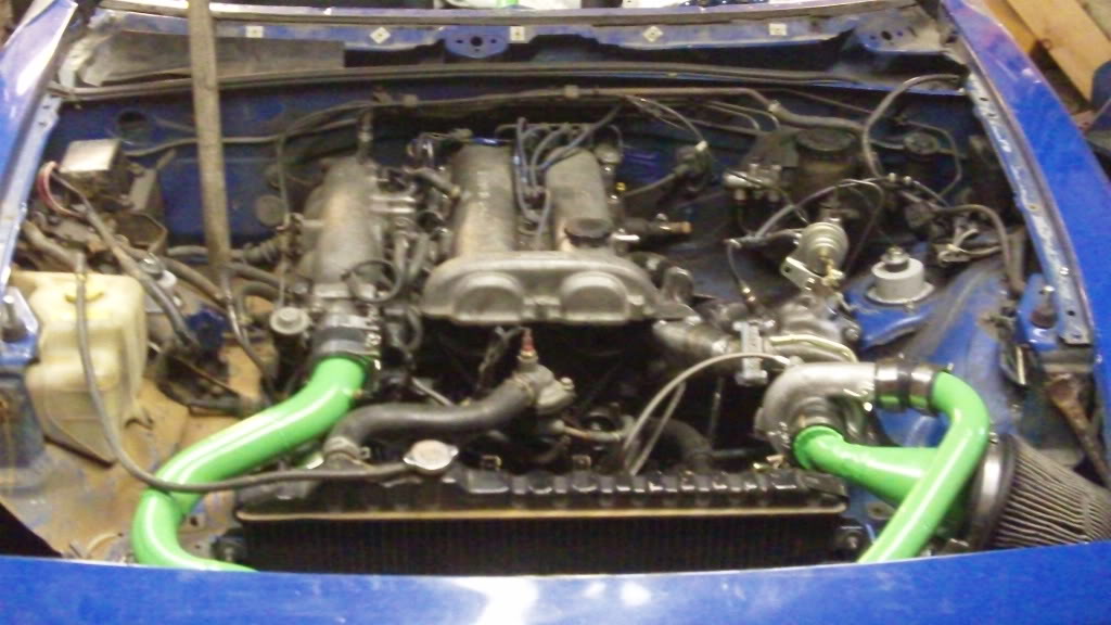
The turbo setup:
TD04L from an 02 WRX
custom manifold and piping
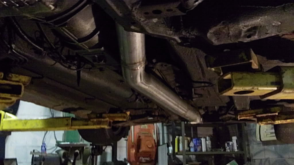
3" downpipe that dumps just behind driver seat
random IC
cheapo BOV that works (it was on a previous car of mine)
550cc injectors
ms1 v3.0
LC1
considering running it on e85
Toyota COP's to go in
Other specs on car:
650/350 springs on race valved konis
isc racing mounts
stock front bar, no rear
torsen
depowered ps rack
custom motor mounts
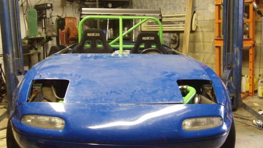
custom roll bar, door skins, and tons of other stuff
13x8 real racing wheels with 20x9.5x13 hoosiers (shown)
13x8 keiser wheels with 21x10x13 hoosiers
13x7's with 225/45/13 toyo R888s for rain/lapping
I still have lots of work to do on the car, but here is where I am right now. If anyone has any suggestions on ways to improve the car or turbo setup, I'm open to it. Also if anyone has a base map (doubtful), I would appreciate it.
I'm getting close to getting the car ready and thought I would show some of my progress.
Everything on the car has been done by my dad and I. The car needs the ms installed and then a trip to the dyno for tuning.
I have very little money in this car (~$2500) mostly as a result of waiting to find deals, making my own parts and selling stuff off the car.
The car is a 90 miata with a stock 1.6. The car has a lot of weight reduction and weighed 1650lbs before the turbo. It still has some more to loose.
The turbo setup:
TD04L from an 02 WRX
custom manifold and piping
3" downpipe that dumps just behind driver seat
random IC
cheapo BOV that works (it was on a previous car of mine)
550cc injectors
ms1 v3.0
LC1
considering running it on e85
Toyota COP's to go in
Other specs on car:
650/350 springs on race valved konis
isc racing mounts
stock front bar, no rear
torsen
depowered ps rack
custom motor mounts
custom roll bar, door skins, and tons of other stuff
13x8 real racing wheels with 20x9.5x13 hoosiers (shown)
13x8 keiser wheels with 21x10x13 hoosiers
13x7's with 225/45/13 toyo R888s for rain/lapping
I still have lots of work to do on the car, but here is where I am right now. If anyone has any suggestions on ways to improve the car or turbo setup, I'm open to it. Also if anyone has a base map (doubtful), I would appreciate it.
Last edited by mikewolf; Apr 17, 2010 at 07:58 PM.
Reply
 0
0

0


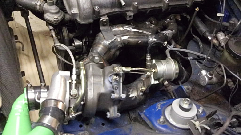
I think your wideband is a bit too close to the turbo, the manufacturers recommend mounting them a little bit further downstream, take some vids when it's done and running.
Reply
0
0


Thread Starter
Junior Member
iTrader: (2)
Joined: Oct 2007
Posts: 140
Total Cats: 0
From: Near buffalo
I realize the wideband is closer than ideal, but my dad put the bung in before I had a chance to tell hime where it goes. I'll move it if it causes problems.
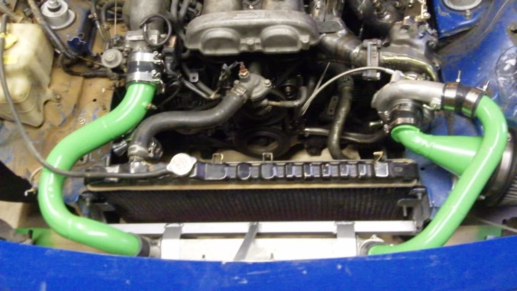
I don't think the intake should have any restriction. It looks lumpy from the outside, but that was to make the coupler fit. On the inside it is all smooth and tapers right down to the same ID as the turbo inlet. My thinking is that if I reduce any restrictions in the intake and DP, I should be able get it spooling quicker.
I don't think the intake should have any restriction. It looks lumpy from the outside, but that was to make the coupler fit. On the inside it is all smooth and tapers right down to the same ID as the turbo inlet. My thinking is that if I reduce any restrictions in the intake and DP, I should be able get it spooling quicker.
Reply
0
0

Thread Starter
Junior Member
iTrader: (2)
Joined: Oct 2007
Posts: 140
Total Cats: 0
From: Near buffalo
Yeah, I had to clock the turbo and it didn't line up and wouldn't clear the hood so I moved the waste gate actuator over to the downpipe. I welded another tab on the waste gate arm so it would move in the proper direction.
I will try to get some better pics up and also some better ones of the manifold.
I will try to get some better pics up and also some better ones of the manifold.
Reply
0
0

Joined: Sep 2005
Posts: 34,433
Total Cats: 7,549
From: Chicago. (The less-murder part.)
Shouldn't matter, so long as the arm is fastened to a point on the actuator that is ~180� away from the original mounting point.
mikewolf, I am really curious about that transition / elbow where you taper down from the filter and turn into the compressor inlet. It looks to me like the whole highlighted area of the compressor inlet is being wasted, and you're creating a bit of a choke point right at the inlet:

I didn't think you guys were required to run restrictor plates. Did I miss something?
mikewolf, I am really curious about that transition / elbow where you taper down from the filter and turn into the compressor inlet. It looks to me like the whole highlighted area of the compressor inlet is being wasted, and you're creating a bit of a choke point right at the inlet:
I didn't think you guys were required to run restrictor plates. Did I miss something?
Reply
0
0
Thread Starter
Junior Member
iTrader: (2)
Joined: Oct 2007
Posts: 140
Total Cats: 0
From: Near buffalo
The inlet to the turbo has a taper in it and the inlet is fairly thick. The ID of inner tube matches perfectly to the ID of the turbo inlet. The tube highlighted by you is only the outer wall that is there to allow a coupler to fit. Hopefully the poorly drawn picture illustrates what I did.
Reply
0
0

Elite Member
Joined: Dec 2008
Posts: 1,642
Total Cats: 36
From: Colorado
Added lightness is pretty kickass.
That looks like the perfect opportunity for a EWG setup, using the existing IWG passage.
Any pics of the inside of the intake right before the turbo inlet?
Edit: Ahh, that explains it. Cool.
That looks like the perfect opportunity for a EWG setup, using the existing IWG passage.
Any pics of the inside of the intake right before the turbo inlet?
Edit: Ahh, that explains it. Cool.
Reply
0
0

Elite Member
Joined: Dec 2008
Posts: 1,642
Total Cats: 36
From: Colorado
It depends on the way the turbine housing is setup, and I dont remember what the WRX stuff looks like off the top of my head. But basically its as follows:
Where you have one big opening into your down pipe right now, you need two. One for the main discharge out of the turbine housing and one for the wastegate passage. They need to be completely separate. On a lot of turbos commonly used here this is a bit tricky (not really) because the turbine housings tend to have one open chamber where the exhaust from the IWG passage and the main discharge both end up as they go into the downpipe. This is solved by adding a divider to the downpipe flange that protrudes into the turbine housing to separate the gasses. BEGI does this IIRC.
http://www.bellengineering.net/produ...roducts_id=138
(You can just barely see the little divider on the DP flange on the right. The EWG would be plumbed in on the smaller tube. You can then ditch the IWG crap and port the hell out of the passage.)
So now you have two separate passages. Any ex gases going through the turbine itself go out the larger one, any ex gases that go through the IWG passage go out another. Now you simply plumb the passage from the IWG to the EWG. You can plumb the outlet of the EWG back to the down pipe a good distance down stream or you can just dump it, which will work really well but be damned loud. Not sure what the noise regs are for you, it often depends on the individual track. PC crap FTW.
The reason I mention it is that EWGs allow for more flow overall and less back pressure, which can be a very good thing on a small turbine housing. With the above setup you can port the living hell out of the IWG passage. EWGs also just plain control boost better. Rather than a simple spring trying to handle valve actuation you actually use the boost pressure itself to modulate the valve, and that means you can get slightly better spool becuse the WG is not cracking open too early, yet at the same time you can also avoid boost creep.
That huge area right above yur DP would be ideal for all this. It might also not be needed. Time and boost logs will tell.
Reply
0
0


Thread Starter
Junior Member
iTrader: (2)
Joined: Oct 2007
Posts: 140
Total Cats: 0
From: Near buffalo
HELP!
I'm supposed to go to the dyno tomorrow morning. I had the car idling before with problems. Now there is oil coming out the exhaust housing. It's not coming from the drain, but the flange where the downpipe bolts up. I have a restrictor in the oil feed. I'm thinking it might be from the engine? I've only run it for 5 minutes and there is a 6" oil spot under the car.
I'm supposed to go to the dyno tomorrow morning. I had the car idling before with problems. Now there is oil coming out the exhaust housing. It's not coming from the drain, but the flange where the downpipe bolts up. I have a restrictor in the oil feed. I'm thinking it might be from the engine? I've only run it for 5 minutes and there is a 6" oil spot under the car.
Reply
0
0


