
My Walbro450 Install

Thread Starter


Joined: Apr 2014
Posts: 18,643
Total Cats: 1,870
From: Beaverton, USA
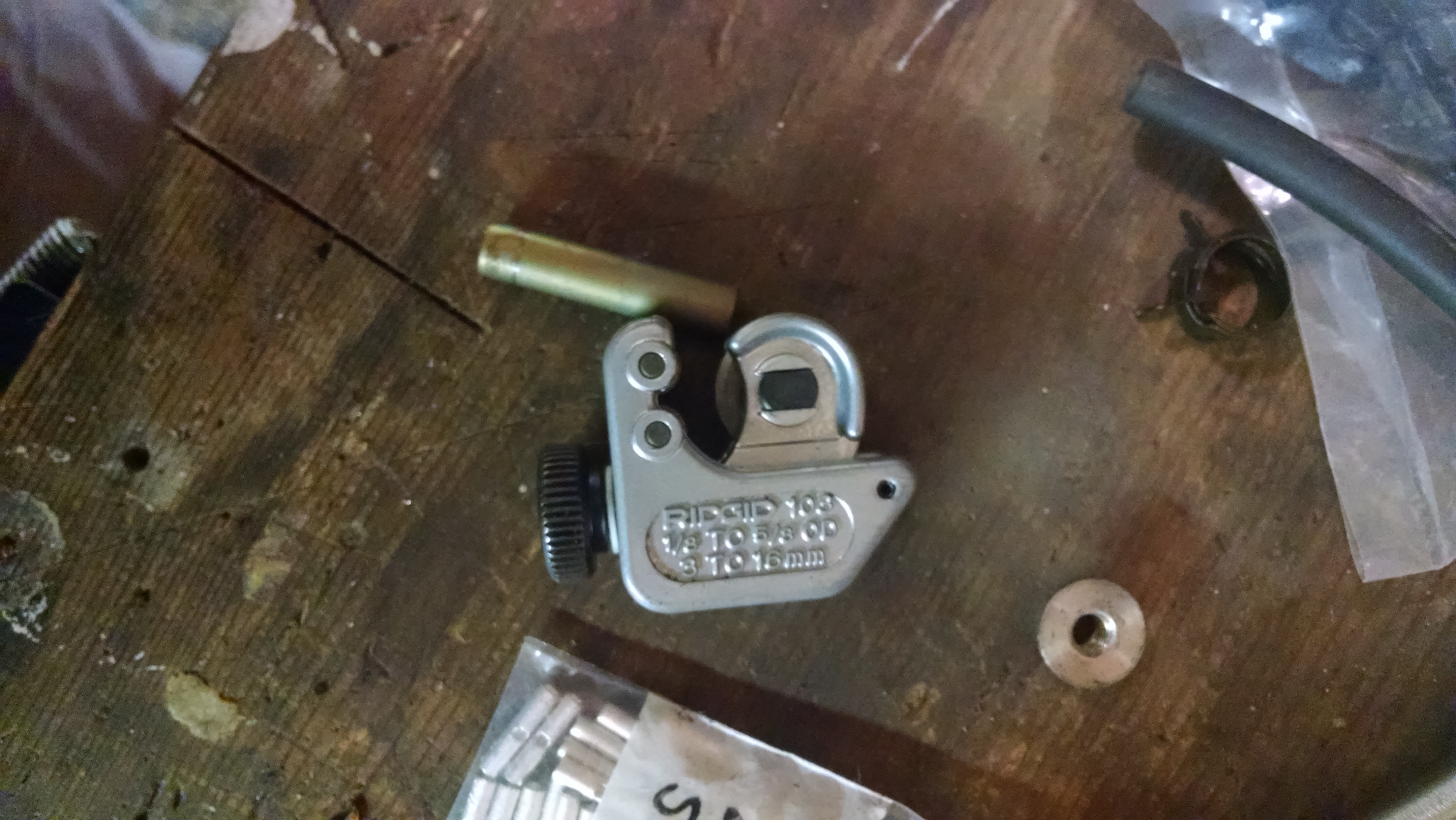
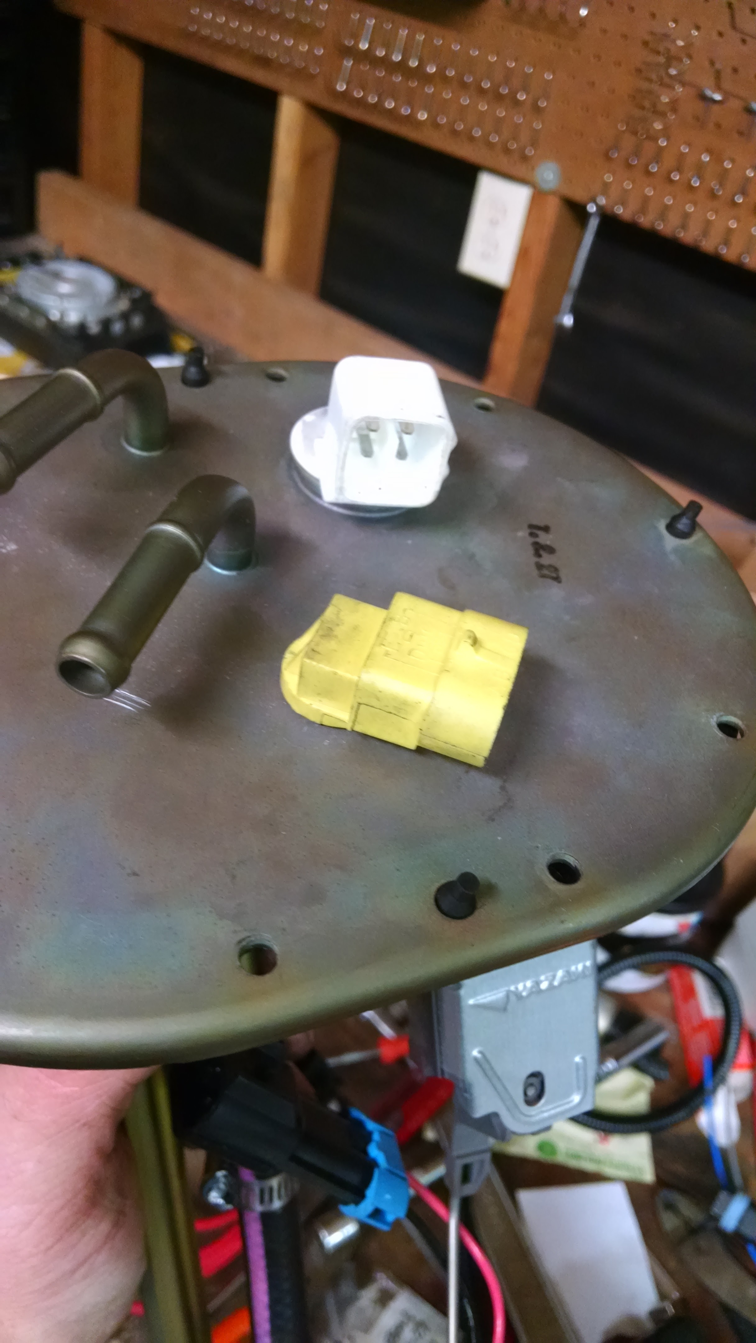
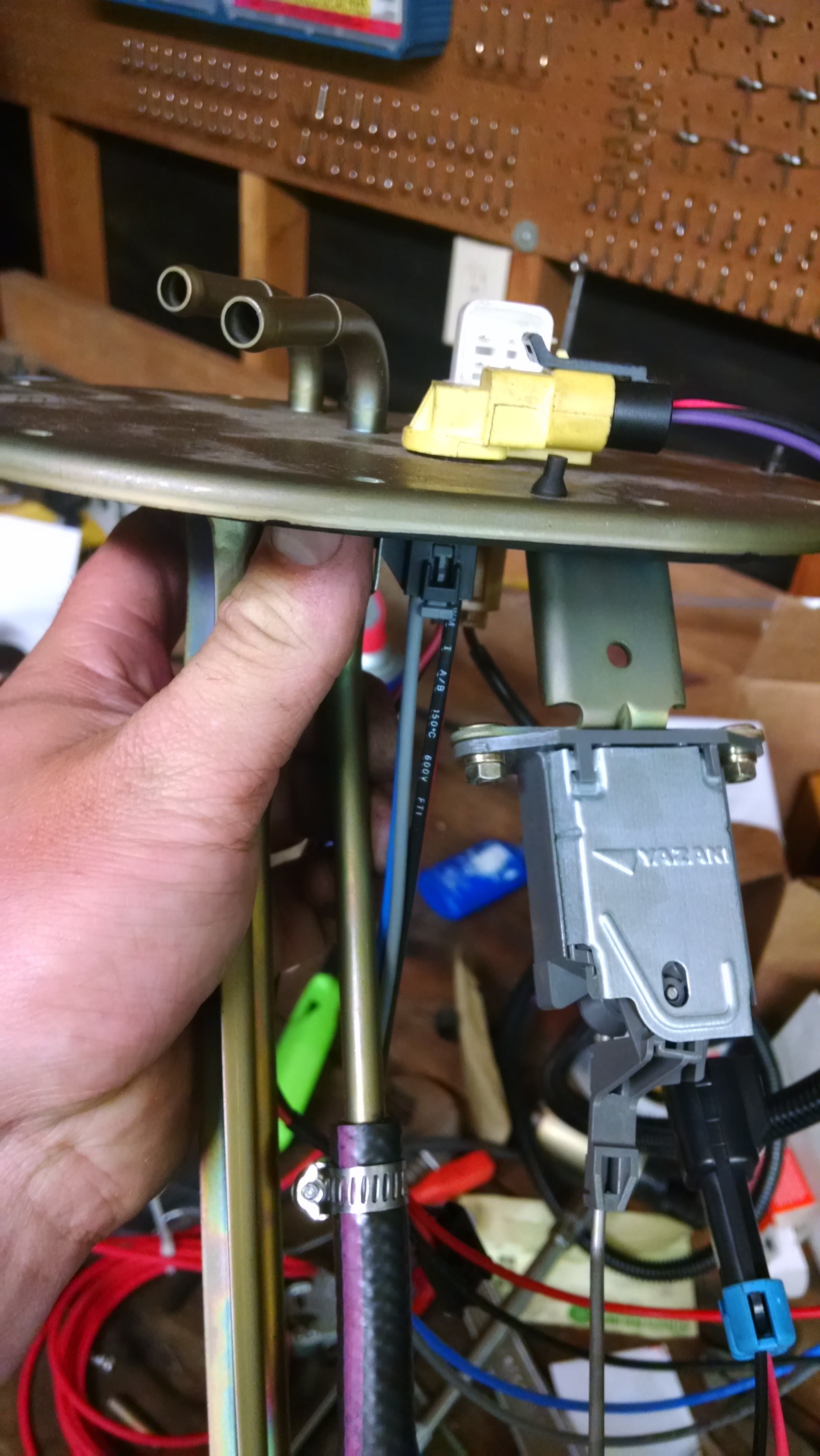
Well the last few people who installed a walbro450 did a **** job of documenting it. (No offense). Probably because it was all covered in fuel and smelly. I'm doing this outside the car with a spare fuel pump assmebly so I took a bunch of pictures.
A couple notes.
- I strongly dislike Racetronix. They charge $50 for a piece of **** bulkhead connector with a shitty mounting tab and shitty everything. It sucks. I hate it. Would not use it. wouldn't even sell it.
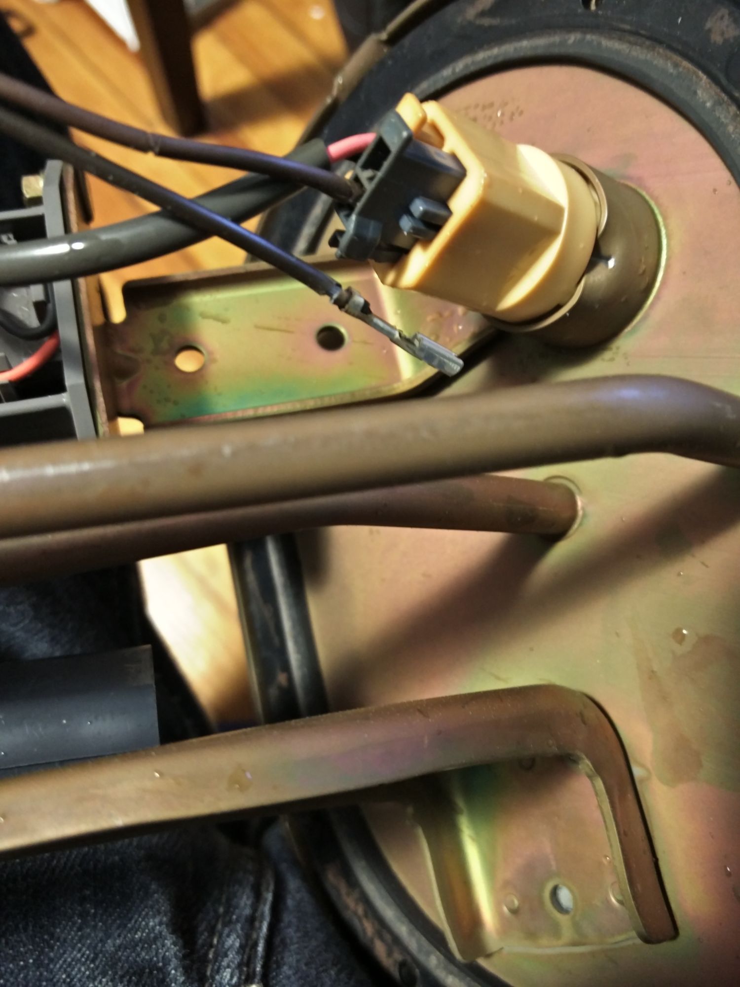
- I reused the stock insulator on the bottom, there might be one that fits a walbro450, but who knows. This one worked.
- I used heatshrink everywhere that metal touched the pump. Trying to keep noise down.
- Waiting on crimpers for 12 gauge wire and then I will wire in the pump with solid state relay.
- Run a stock sock instead of the walbro sock. So you don't get fuel starvation.


A couple notes.
- I strongly dislike Racetronix. They charge $50 for a piece of **** bulkhead connector with a shitty mounting tab and shitty everything. It sucks. I hate it. Would not use it. wouldn't even sell it.
- I reused the stock insulator on the bottom, there might be one that fits a walbro450, but who knows. This one worked.
- I used heatshrink everywhere that metal touched the pump. Trying to keep noise down.
- Waiting on crimpers for 12 gauge wire and then I will wire in the pump with solid state relay.
- Run a stock sock instead of the walbro sock. So you don't get fuel starvation.
Last edited by aidandj; Jun 11, 2016 at 05:18 PM.
Reply
 0
0

0


What would you do differently if the Racetronix stuff was a pita?
You say 1.6L, the NA6 has the funky flange cap thing that the pump nests into right? Did you just cut that off, flare, and slip a hose over?
You say 1.6L, the NA6 has the funky flange cap thing that the pump nests into right? Did you just cut that off, flare, and slip a hose over?
Reply
0
0
If you don't have heat shrink, I've just split a piece of fuel hose and used that as a rubber insulator. Works well, and of course is fuel safe.
Install looks good, it's cleaner than mine! I didn't take pics either, but mine is a mess with twin pumps. Putting the 450 in wasn't that hard surprisingly. I used the OEM sock on mine as well.
Last question, so what's the best way to run wires through now?
Install looks good, it's cleaner than mine! I didn't take pics either, but mine is a mess with twin pumps. Putting the 450 in wasn't that hard surprisingly. I used the OEM sock on mine as well.
Last question, so what's the best way to run wires through now?
Reply
0
0
Thread Starter
Joined: Apr 2014
Posts: 18,643
Total Cats: 1,870
From: Beaverton, USA
I don't really know. I had a bad experience with their service. And then the way they mount the bulkhead fitting sucks. But I couldn't find anything else comparable on the market.
No idea on the flange cap. This pump assembly might be from a later NA.
No idea on the flange cap. This pump assembly might be from a later NA.
Reply
0
0
Thread Starter
Joined: Apr 2014
Posts: 18,643
Total Cats: 1,870
From: Beaverton, USA
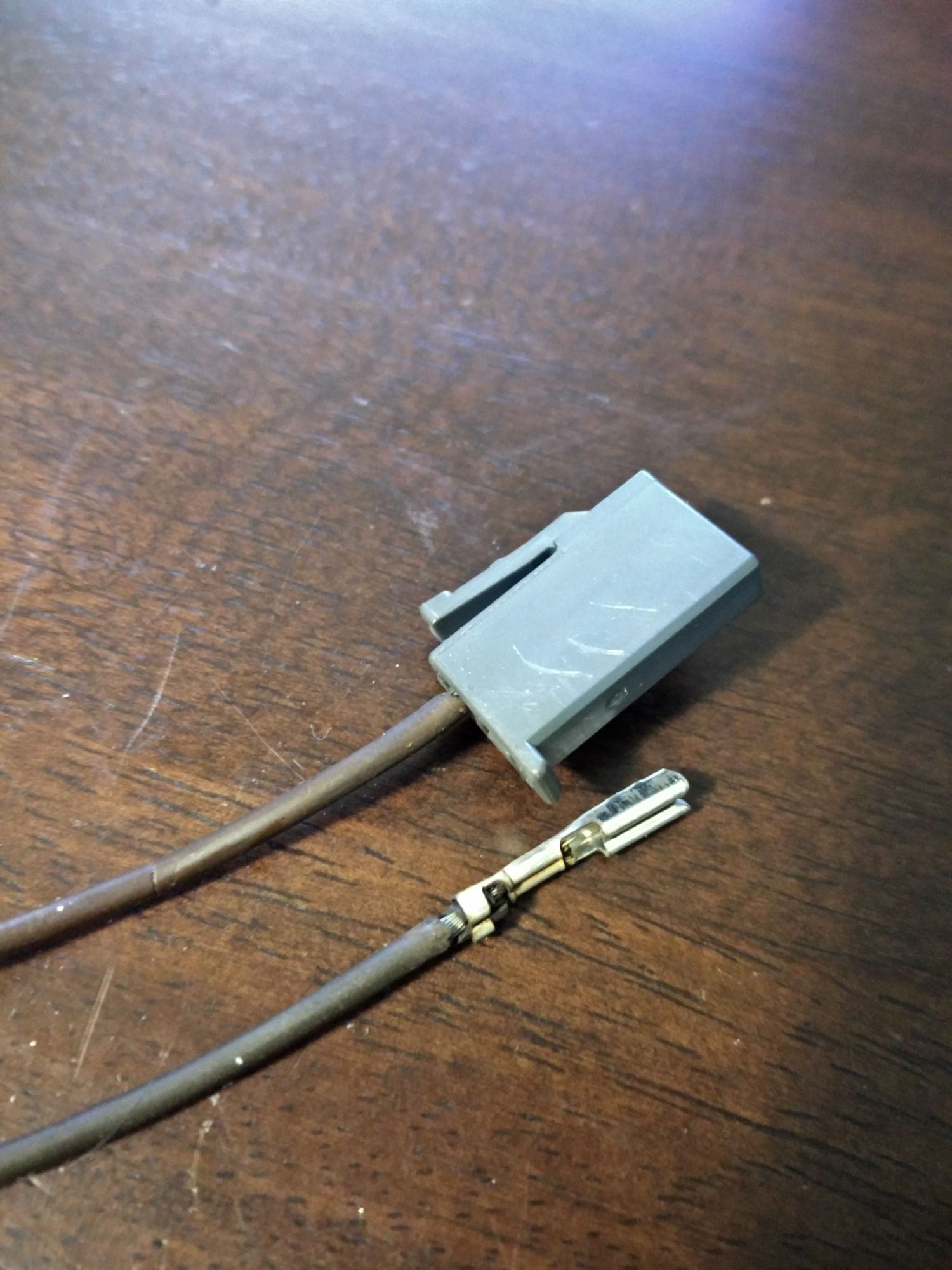
I really don't want to say the racetronix bulkhead connector because I dont like it. The way it mounts sucks. I had to basically hammer the clip on with a socket. But I searched for a while and never found anything that was comparable. I wrote last night's post still salty from trying to **** with the clip for 20 minutes. It isn't as bad as I made it out. But it's the only thing out there so I used it.
2 wires crimped into 1 12awg wire. Then into the fuel pump connector.
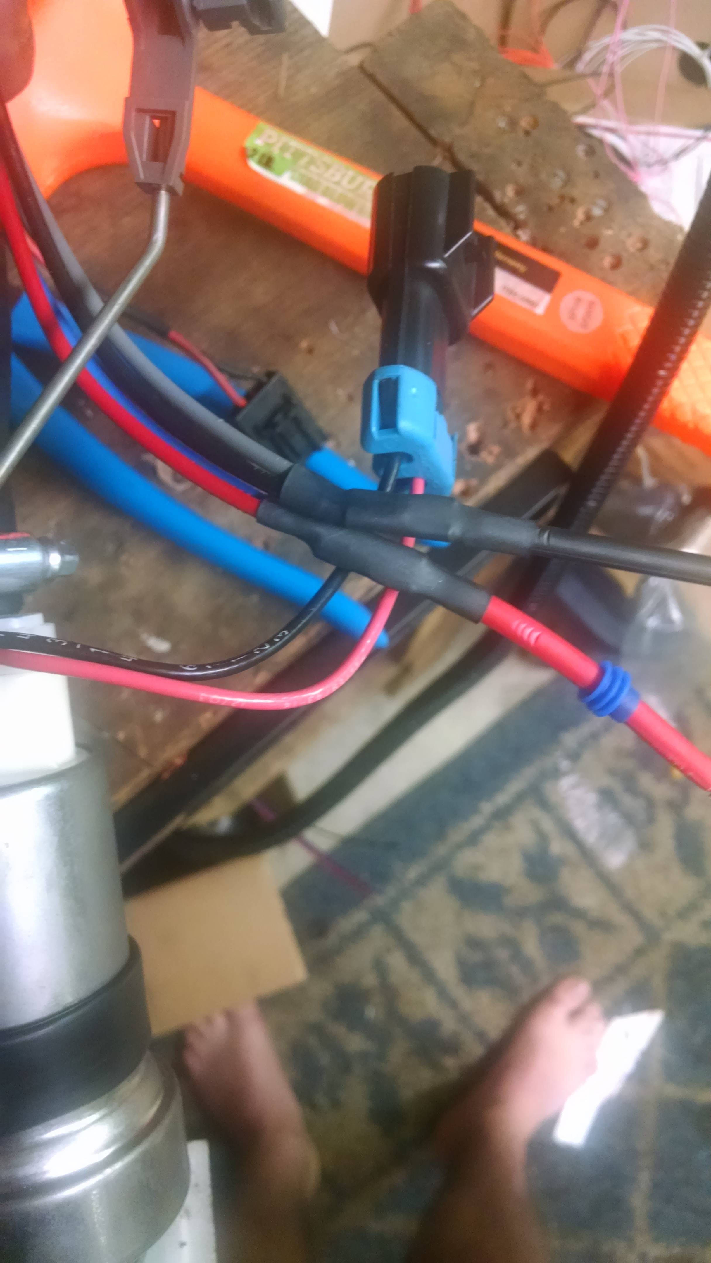
2 wires crimped into 1 12awg wire. Then into the fuel pump connector.
Reply
0
0

Has anyone measured the voltage loss over the short run of OEM-gauge wire that would be left if you were to plumb a 12ga or 14ga wire into the stock wire and through the stock connector? How much is actually lost through that 6" of wire? I've always questioned whether a separate bulkhead connector is actually necessary.
Reply
0
0
Thread Starter
Joined: Apr 2014
Posts: 18,643
Total Cats: 1,870
From: Beaverton, USA
Well the connector on the pump is 14gauge. So you have 4 inches. There. Nothing you an do about that.
It's not a lot. Probably less than a percent. But you also have a lot of current through some small pins on the stock connector. If I were to do it again I would use the stock connector. I bought the racetronix bulkhead connector during their black friday sale on an impulse buy.
It's not a lot. Probably less than a percent. But you also have a lot of current through some small pins on the stock connector. If I were to do it again I would use the stock connector. I bought the racetronix bulkhead connector during their black friday sale on an impulse buy.
Reply
0
0
You can calculate it with very high accuracy if you really want to know what the voltage drop will be. There are even tables for it to make it very simple. I posted a thread here measuring voltage drop a year or two ago, and the measured vs calculated voltage drops were very much in agreement.
14awg wire
14 volts DC
20amps
6" run
Voltage drop is approximately 0.051v, 0.36%. Hard to justify a bulkhead connector for that

I am going to switch to a solid-state relay plumbed from the battery, but my plan is to run the wiring through the stock connector.
Reply
0
0
From: Voltage Drop Calculator
14awg wire
14 volts DC
20amps
6" run
Voltage drop is approximately 0.05v. Hard to justify a bulkhead connector for that
I am going to switch to a solid-state relay plumbed from the battery, but my plan is to run the wiring through the stock connector.
14awg wire
14 volts DC
20amps
6" run
Voltage drop is approximately 0.05v. Hard to justify a bulkhead connector for that
I am going to switch to a solid-state relay plumbed from the battery, but my plan is to run the wiring through the stock connector.
Agreed that you don't have to do it though, just running beefy wires to the connector will get you 95% of the way there.
Reply
0
0
Thread Starter
Joined: Apr 2014
Posts: 18,643
Total Cats: 1,870
From: Beaverton, USA
I think the hella SSR and ms3 PWM pump control is going to be the new "go-to" solution for a big pump on a stock returnless system.
I'm waiting on some 12g spade connectors and then will wire in my SSR. I'll write up the connections I make. I'm going to jump the stock relay and use the stock wiring to control the SSR.
I'm waiting on some 12g spade connectors and then will wire in my SSR. I'll write up the connections I make. I'm going to jump the stock relay and use the stock wiring to control the SSR.
Reply
0
0
I agree. Flow Force 640cc EV14s + solid-state relay + MS3 PWM control + DW200/300 will take you to the limits of an EFR6258 on a stock returnless setup without compromising idle quality. I will be forced to add a boost-referenced FPR to crack the 400whp barrier, but for most people, SSR+PWM+DW200 will be the easiest, least expensive fuel system setup.
Reply
0
0
Thread Starter
Joined: Apr 2014
Posts: 18,643
Total Cats: 1,870
From: Beaverton, USA
I will mostly be interested in seeing if open loop pwm settings can be shared. Would be cool if we could get a database going of what PWM=what pressure/flow. Or at least a ballpark number.
I'll have a fuel pressure sensor, but I'm also on a boost referenced FPR.
I'll have a fuel pressure sensor, but I'm also on a boost referenced FPR.
Reply
0
0
Thread Starter
Joined: Apr 2014
Posts: 18,643
Total Cats: 1,870
From: Beaverton, USA
Dug up the fuel pump relay diagrams.
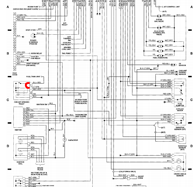
The idea is to use the stock fuel pump wiring all the way to the tank. But only as the signal for the relay. So the stock relay is ditched. and the light green wire is connected to the blue and red wire. Note: This will only work if you have jumped the AFM connector, which connects the light green wire to the ECU fuel pump output.
This gives us a direct signal wire from the ECU to the fuel pump. Then that signal wire gets connected to the negative pin of the SSR. And the positive pin gets connected to 12v. Then the power pins of the SSR get the 12gauge wire from the battery, and then 12 gauge wire to the pump.
Someone please correct me if I'm wrong. (@Joe Perez or @Ben maybe)
Reply
0
0
SAV, so grab this connector with 14 gauge: Home � Shop � Connectors / Harnesses � Delphi / Packard � Pigtails � GM Delphi / Packard - 2 way MP280 Pigtail for Walbro 450 pump & larger fuses
then repin the underside of stock feedthrough, and use 12 gauge up top harness-side?
then repin the underside of stock feedthrough, and use 12 gauge up top harness-side?
Reply
0
0
or go straight for a 10-12 gauge set
Metri-Pack 280 - 630
[img][/img]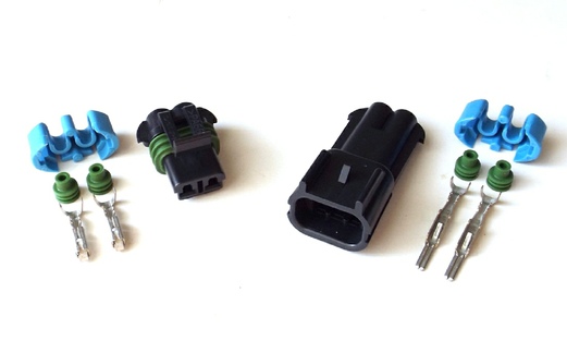
edit: deleted incompatible product
Metri-Pack 280 - 630
[img][/img]
edit: deleted incompatible product
Reply
0
0
Reply
0
0


