
New Turbo Manifold Design


heheheheheeee yeah man go ahead and make this manifold. It's the best design so far! Enjoy fabing the merge...getting all 4 pipes pointing where they should is tricky. I have done it a few times to know some secrets. It will be easier to buy one of those prefabbed merges from ETD/Vibrant/etc and making tubular manifold. Or buy mine for $550 is cheaper than doing it yourself, even factoring in $5/hr. 
I will not comment on that EWG location, other than an upcoming manifold of mine won't have it where you put it.
I also model all my manifolds in solidworks. Mines a little different than yours, and yeah I use T2 flanges mostly.
I will not comment on that EWG location, other than an upcoming manifold of mine won't have it where you put it.
I also model all my manifolds in solidworks. Mines a little different than yours, and yeah I use T2 flanges mostly.
Reply
 0
0

0
The way Tim did it, the merges are all on planes (he might even use a band saw, like the instructions for a straight merge on the Weirtech site). You can lay it out with pencil and paper, ruler and compass.
This Solidworks model is pretty, but the merges are complex 3D shapes. I can't figure out how to make them other than by spending 1000 years with cut and fit or CNC.
I think I've figured out how to make my merges at least planar, and lay it out and fabricate it, but there's a chance the tubes won't actually intersect each other perfectly at the planes. I don't have a Solidworks seat at work. I've thought about trying to use Google's free CAD.
Yeah my standard T2 Absurdflow does meet in planes, I guess it could make it easier, but I have found it doesn't matter much whether it's a straight cut or a 3d profile'd cut. It'd need to be tweaked regardless...unless you get it CNC'd of course! I do have a version of a manifold that's a bottom and a top half that's CNC'd and then welded together. A big chunk of raw material isn't as expensive as you'd think. Now if I can get in good with a CNC guy...
3D shapes are fun:

Reply
0
0


I have heard CATIA is fantastic, though I have never used it.
I know someone who is playing around with the Google freeware solid modeler and they like it. I have watched them use it and the interface is nice.
Reply
0
0

Newb
Joined: Jan 2009
Posts: 19
Total Cats: 0
From: Coventry, UK
If you think Solidworks is bad, you should try Pro/E! I have been back and forth between Pro/E and Solidworks, and Solidworks is a lot easier to use.
I have heard CATIA is fantastic, though I have never used it.
I know someone who is playing around with the Google freeware solid modeler and they like it. I have watched them use it and the interface is nice.
I have heard CATIA is fantastic, though I have never used it.
I know someone who is playing around with the Google freeware solid modeler and they like it. I have watched them use it and the interface is nice.
Reply
0
0

Thread Starter
Former Vendor
iTrader: (8)
Joined: Mar 2005
Posts: 1,185
Total Cats: 57
From: Broken Arrow,Ok
Ye of little faith.. I'm still playing with the model to find the best plan of attack for the fabrication part of it. I'm sure the merge will take some time and patience, but hopefully utilizing a CNC will make it a little less painful. I'm going to try to machine the flanges this week and then order the tubing. I'll probably go ahead and fab up a new 3" exhaust w/out a muff while I've got the new mani going on. I've convinced myself I don't drive it enough to worry about it being quiet. I'll keep you guys updated.
-Michael
-Michael
Reply
0
0

Junior Member
Joined: Sep 2007
Posts: 109
Total Cats: 0
From: Brisbane, Australia
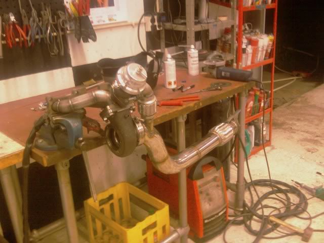
Looks familiar. Very similar to the one I was thinking of doing. And here is the one I actually did, basically a simplified version since I was making it with basic tools at home. Thanks to TurboTim for the inspiration 


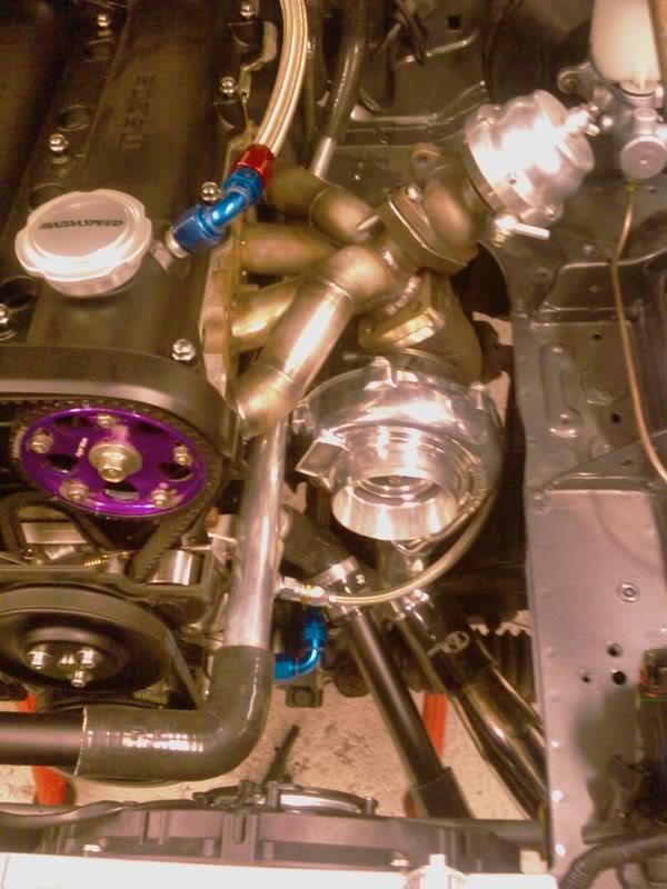
Oh, and installed pic too. There is actually more room than I thought to the chassis rail. Don't think you would get a EWG in there for the shock tower however...

Tim
Oh, and installed pic too. There is actually more room than I thought to the chassis rail. Don't think you would get a EWG in there for the shock tower however...
Tim
Reply
0
0
Tim,
haha that's sweet! I doubt there's any difference between what you ended up doing and what you modeled/mine.
Michael,
I have faith! It's not hard to do, it just takes time. If you're doing it yourself, time is free. I'm sure you will make something great.
Saitrix,
I don't think making manifolds is difficult at all, like I said it just takes time and patience. The only specialized piece of equipment I have is my TIG. My first few manifolds were made using my dremel and a sleeve of those brown �1" cutoff wheels. Now I use a $9 harbor freight 4.5" angle grinder with a nice cutoff wheel, and the dremel in tight corners. A $9 die grinder cleans up the burrs.
Finally, I use a chop saw on exhaust tubing. That's really it.
Reply
0
0
Newb
Joined: Jan 2009
Posts: 19
Total Cats: 0
From: Coventry, UK
TurboTim,
Awesome that is good to know, really tempted to do my own now. Only problem is all I have is an arc welder, but should be good enough for the job.
zoomzoom,
I like the simplified design there.
Awesome that is good to know, really tempted to do my own now. Only problem is all I have is an arc welder, but should be good enough for the job.
zoomzoom,
I like the simplified design there.
Reply
0
0

Junior Member
Joined: Jun 2005
Posts: 286
Total Cats: 235
just saw this.. looks almost exactly like the one i made for mine 
But i put the turbo on at a slight angle. makes it A LOT easier to reach the bolts for the turbo with the manifold in the car..
edit..
btw.. i did no fancy cad design models.. i just build nice parts design them as i go
But i put the turbo on at a slight angle. makes it A LOT easier to reach the bolts for the turbo with the manifold in the car..
edit..
btw.. i did no fancy cad design models.. i just build nice parts
design them as i go
Reply
0
0

straightlinespecialties
Joined: Jan 2009
Posts: 26
Total Cats: 0
Problem is you have to come up w/ a solution for the lower radiator hose and heater core hose. I went rounds and rounds w/ this when design my manifold and finally gave up and designed the manifold and a water kneck to reroute the lower hose.
Reply
0
0
Junior Member
Joined: Jun 2005
Posts: 286
Total Cats: 235
if you have the skills to fabricate a proper manifold, making the small changes to the coolant system should be easy .
Reply
0
0
straightlinespecialties
Joined: Jan 2009
Posts: 26
Total Cats: 0
Reply
0
0
Junior Member
Joined: Jun 2005
Posts: 286
Total Cats: 235
not really, but it forces a few new parts, and kicks the price up.. makes servo / ac impossible etc.. can fully understand why kit manufacturers dont make kits like this..
Reply
0
0
For a bolt-on solution you could either use the BEGI coolant bypass/reroute thingie or for a less expensive and more custom idea you can bolt a stock waterneck to the waterpump inlet and have it point forward, getting rid of the mixing manifold. This second option requires you to do something with the heater core hoses but isn't too difficult. This is what Paul did on his and Artie's I think.
BEGI solution:
http://www.bellengineering.net/produ...roducts_id=312

Reply
0
0
^^ I just installed one of the BEGI water pump inlets shown above. I just bought the inlet itself and sourced my own hoses. I had to add some spacers to the tensioner pulley bracket to move it about 1/4" away from the engine so it would clear the neck (the tensioner that is used with A/C and no PS). Other than that, which is minor really, it works great.
I needed it because the stock water neck routing would not clear the relatively large GT2871 compressor housing using the S4 manifold.
I needed it because the stock water neck routing would not clear the relatively large GT2871 compressor housing using the S4 manifold.
Reply
0
0
straightlinespecialties
Joined: Jan 2009
Posts: 26
Total Cats: 0
For a bolt-on solution you could either use the BEGI coolant bypass/reroute thingie or for a less expensive and more custom idea you can bolt a stock waterneck to the waterpump inlet and have it point forward, getting rid of the mixing manifold. This second option requires you to do something with the heater core hoses but isn't too difficult. This is what Paul did on his and Artie's I think.
BEGI solution:
BEGi Water Bypass System BEGi
BEGI solution:
BEGi Water Bypass System BEGi
Reply
0
0
Yeah I looked at flipping over the stock water neck. But I would have had to slice off the protrusion for the heater core return hose and weld it up since it would have had a big clearance issue with the tensioner bracket. It was more trouble than it was worth for me, so I went the turn-key route.
Reply
0
0
Junior Member
Joined: Sep 2007
Posts: 109
Total Cats: 0
From: Brisbane, Australia
A welch plug takes care of the old heater inlet, and as part of my coolant reroute I had already relocated the heater return into the top hose, I used a 5/8 bard to 16mm banjo fitting to return the heater into the top of the 1.6 thermostat housing on the back of the head. A right angle 3/8 barb is fitted into the old throttle body water line for the turbo water cooling return.

Reply
0
0

Thread
Thread Starter
Forum
Replies
Last Post


