When you click on links to various merchants on this site and make a purchase, this can result in this site earning a commission. Affiliate programs and affiliations include, but are not limited to, the eBay Partner Network.
Ive seen a lot of people reccomend the .86 housing over the .64. Im sure the EGT is lower with the .86 as it flows more, but you also get more lag and worse transient response from the turbo. I have seen dynos of cars that use a .64 housing and they make 400+ whp. I think for most people the .64 would be ideal unless you are tracking your car, or want all out topend power. I could see on a track how the higher flowing housing would be the one to choose for lower egt and better topend since you arent running lower rpms. For a street car I would choose the .64 but thats just me.
I spent all of this evening trying to get to the bottom of this. I've made some progress but still have some way to go.
My first step was to verify that the turbosmart actuator was responding as expected. A bit of bodgery later and I had a tyre compressor hooked up to my actuator, which wasn't ideal since I couldn't use an accurate gauge and the inbuilt one in the compressor would have to do.
This confirmed that the actuator is working without leaks. I measured the total travel of the WG arm pin to be 22mm and the turbosmart actuator with 1mm of preload to have 16.5mm of usable travel. Measuring the displacements at various pressures gave the following plot.
Bearing in mind the potential measurement error with the inbuilt pressure gauge, the trend looked fairly clear (I wasn't expecting as smooth a trendline as this!). Interestingly, past 13psi, the pressure required to compress the spring appears to ramp up, suggesting that the spring could be getting near coil bound. This suggested to me that a longer spring with a lower k-factor but more preload (in terms of distance, obviously same in terms of force) to make it the same pressure may help creep at higher boost levels by letting the WG open further for a given pressure, but only if the WG could flow enough when fully open....
A bit of lockwiring later and I had this.
Now it took until 5000rpm before ~6.5psi (seemingly the effective stiffness of my 7psi spring) was exceeded, but it still hit ~17psi at 6500rpm. This tells me what we already knew, that my wastegate can't flow enough and needs porting.
I then removed the lockwire, reattached the actuator (bypassing the solenoid) and took a measurement. Looking at the data, I was trying to work out why the MAP signal looked so noisy, turns out windowed MAP sensing was on... I disabled this for the plot below (though I realise this will make numbers incomparable, but by the time I realised, it was too late to do another lockwire run)
With the actuator hooked up, 6.5psi was reached around 3k, held to 4k then creep started at around 5psi/1000rpm to hit ~18psi at 6500rpm. This suggests that the actuator is letting the wastegate open to near the wired open position.
It now looks like I need to port this wastegate and perhaps a longer, lower k-factor spring could help the marginal system if I could get the creep down to say 12psi.
Interestingly, the turbosmart actuator comes with 2 springs for its 14psi rating, an inner 7psi 43mm long spring and an outer 7psi 57mm long spring. The instructions say to run the inner spring only for 7psi and I thought this made sense from the smaller diameter spring having less resistance to rod misalignment, but I'm wondering if the 7psi 57mm long spring would remain linear during the whole travel and being less stiff (I think the installed lengths are similar though didn't measure or take pictures when I removed the outer spring) it might need less pressure to reach the 16.5mm endstop.
I've been looking at the FM2 downpipe pictures and I'm pretty sure a fair bit of my IWG divider is missing. I'm guessing that is a factor here too. Before I go removing the turbo, does anyone know if you can remove the turbo on an FM2 kit without having to take the first part of the exhaust with it along with that awful slip joint? I've removed it once before and it wasn't fun at all.
Originally Posted by codrus
Lowest I've ever tried is 7 psi, and it made 7 psi flat to redline.
Once you've used an EWG you'll never want to go back to an internal gate.
--Ian
That does sound very good. Is it a lot better at controlling boost too? In the midrange, before the creep goes mad, it looks like each duty cycle % is around 5kPa, which will probably be difficult to tune accurate closed loop with.
Originally Posted by sixshooter
Ditch the .64 for a .86.
Is this for boost creep reasons or more generally for my turbo? Obviously if going EWG, I'd need a new housing and would have that option, but I'd probably value throttle response over an extra 20whp extra... But then I don't know how much of an EGT limit I'd run into on track with the 0.64.
Originally Posted by andyfloyd
I was getting really bad creep on my 2560 .64 housing before I ported it. I opened up the wg hole, and ported a channel to the wg to help the exhaust to find its way out a little easier. Now I can run as low as 10psi, it still wont really go lower than that but I was getting uncontrolled creep previously past 5000rpm. As for your high EGT readings I think Ken is onto the right path. Something tells me the cam timing must be off, maybe that is also why it is spooling so fast as well.
Interesting, perhaps that is the same housing as this one. Do you have any before/after pictures? Was your creep similarly bad to mine beforehand?
The 64 is really small and will require a significant wastegate flow to keep from creeping. But you know this. Boost is a measure of back pressure in the system. A significant source of back pressure in the system is the turbine housing unless the wastegate is very large.
I've been looking at the FM2 downpipe pictures and I'm pretty sure a fair bit of my IWG divider is missing. I'm guessing that is a factor here too. Before I go removing the turbo, does anyone know if you can remove the turbo on an FM2 kit without having to take the first part of the exhaust with it along with that awful slip joint? I've removed it once before and it wasn't fun at all.
The FM setup is designed so that the manifold, turbo, and "elbow" outlet casting go into/come out of the car as a unit, and are then further disassembled on the bench.
The four bolt flange between the elbow and the DP is a PITA to do in the car, but with an appropriate mix of extensions, u-joints, gear wrenches, etc it's more doable than trying to get the bottom nuts on the turbo-to-elbow flange.
Something really doesnt sound right here. Can you remove a cat and run open pipe for a (loud and obnoxious) test? I have run both a 64 and an 86 IWG turbine on a gtx28, and dont see this at all.
I had a similar experience to Erat on my old setup - begi cast manifold, GT2060RS (not X) 0.64, FM elbow, FM 3" exhaust.
With the 7 PSI garrett actuator it would creep to something like 11-12PSI at redline. I opened up the area behind the wastegate 'penny', probably about 1/8" all the way round, the route of the gasses from the exhaust manifold to that area, and the way out on the FM elbow side.
It would still creep a tiny amount, maybe 1-2PSI extra at redline - nothing like as bad as it was before...
Turbos with small, restrictive internal wastegates will tend to creep when paired with a free-flowing exhaust. The nice open exhaust means that it's "easier" for the exhaust to flow through the turbine (thus delivering power to the compressor) than it is to flow through the wastegate.
To fix it you need to flip the balance of these two paths. Either make it easier to flow exhaust through the wastegate (porting, EWG, etc) or harder for it to flow through the turbine. The latter is easier, but kind of dumb.
The 64 is really small and will require a significant wastegate flow to keep from creeping. But you know this. Boost is a measure of back pressure in the system. A significant source of back pressure in the system is the turbine housing unless the wastegate is very large.
This is interesting, I thought the reverse would be true, increase the flow resistance with a smaller turbine and the pressure differential across the turbine would increase, increasing the flow through the WG hole?
Is there any data available for creep on the same system but with different A/Rs?
I do think at the power I ultimately want to run on track, 0.86 would be better for that, but since street response is also very important to me, I'd like to try and make 0.64 work.
Originally Posted by codrus
The FM setup is designed so that the manifold, turbo, and "elbow" outlet casting go into/come out of the car as a unit, and are then further disassembled on the bench.
The four bolt flange between the elbow and the DP is a PITA to do in the car, but with an appropriate mix of extensions, u-joints, gear wrenches, etc it's more doable than trying to get the bottom nuts on the turbo-to-elbow flange.
--Ian
Thanks, I'll try it this way. Previously I left that joint alone and undid the exhaust at the flange to the midpipe but that was quite unwieldy. I took the slip joint off too but can't remember why that was necessary. It was hard work doing that!
Originally Posted by Ted75zcar
Something really doesnt sound right here. Can you remove a cat and run open pipe for a (loud and obnoxious) test? I have run both a 64 and an 86 IWG turbine on a gtx28, and dont see this at all.
There is no CAT here. Do you have any plots of the minimum pressures you could run with either of those?
Oddly a friend with the same manifold + DP, a similar 2.5� exhaust but a stock NA8 engine, can hold 7psi to redline with a 64 GT2560 which is confusing me.
Originally Posted by Ted75zcar
Do you make 18psi worth of power, are you burning 18psi worth of fuel?
At 11:1 and 17psi with WG open, my 650CC injectors at 45psi vac referenced were at 87% duty which sounds like 18psi worth of fuel to me?
Originally Posted by jonboy
I had a similar experience to Erat on my old setup - begi cast manifold, GT2060RS (not X) 0.64, FM elbow, FM 3" exhaust.
With the 7 PSI garrett actuator it would creep to something like 11-12PSI at redline. I opened up the area behind the wastegate 'penny', probably about 1/8" all the way round, the route of the gasses from the exhaust manifold to that area, and the way out on the FM elbow side.
It would still creep a tiny amount, maybe 1-2PSI extra at redline - nothing like as bad as it was before...
Thanks for sharing your experience. If that took yours from 11-12 down to 8-9, that percentage might be enough for me. Did you find it affected your boost control duties much?
My boost control duties look like in the midrange that each 1% duty is worth 3-4kPa, which if that became coarser might be an issue. 2000rpm 3k pulls at 2% duty intervals shown for reference.
Originally Posted by codrus
Turbos with small, restrictive internal wastegates will tend to creep when paired with a free-flowing exhaust. The nice open exhaust means that it's "easier" for the exhaust to flow through the turbine (thus delivering power to the compressor) than it is to flow through the wastegate.
To fix it you need to flip the balance of these two paths. Either make it easier to flow exhaust through the wastegate (porting, EWG, etc) or harder for it to flow through the turbine. The latter is easier, but kind of dumb.
--Ian
Ian, what sort of resolution do you see with your setup? I'm quickly coming round to the idea that it looks to be the best for what I'm after, high power on track (EGT control + 3" exhaust), good boost by TPS (ability to control to low pressure) but also good response (0.72)
I think the key here is the 3” exhaust. I have a 3” downpipe as well, I think it flows too well for that internal wg hole. If I knew last year what I know now, I would have just gone with an external wastegate setup.
You'd think that by now with what 30-40 years of experience and like 10 revisions later, garrett would finally fix such a stupid issue, but here we are
Just port it like everyone else, its a 5 minute die grinder job and it's sweet then.
Dann
That's that plan. I have the turbo off now, so a job for the weekend
Originally Posted by 18psi
You'd think that by now with what 30-40 years of experience and like 10 revisions later, garrett would finally fix such a stupid issue, but here we are
That is annoying, especially as you can see how Borg Warner really designed the EFR WG from the off to actually work.
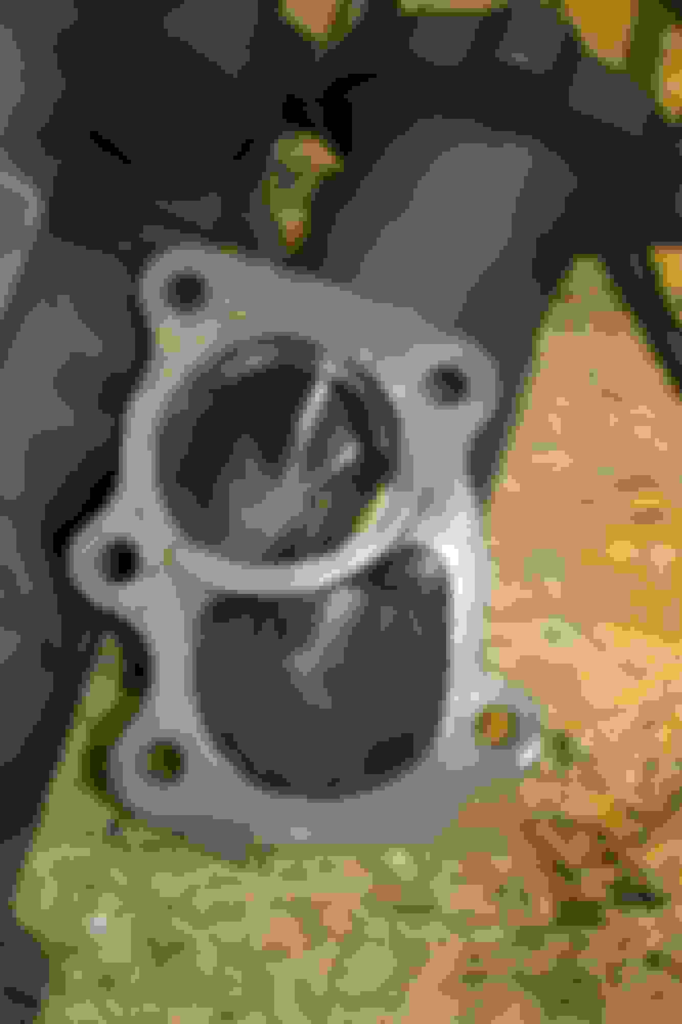
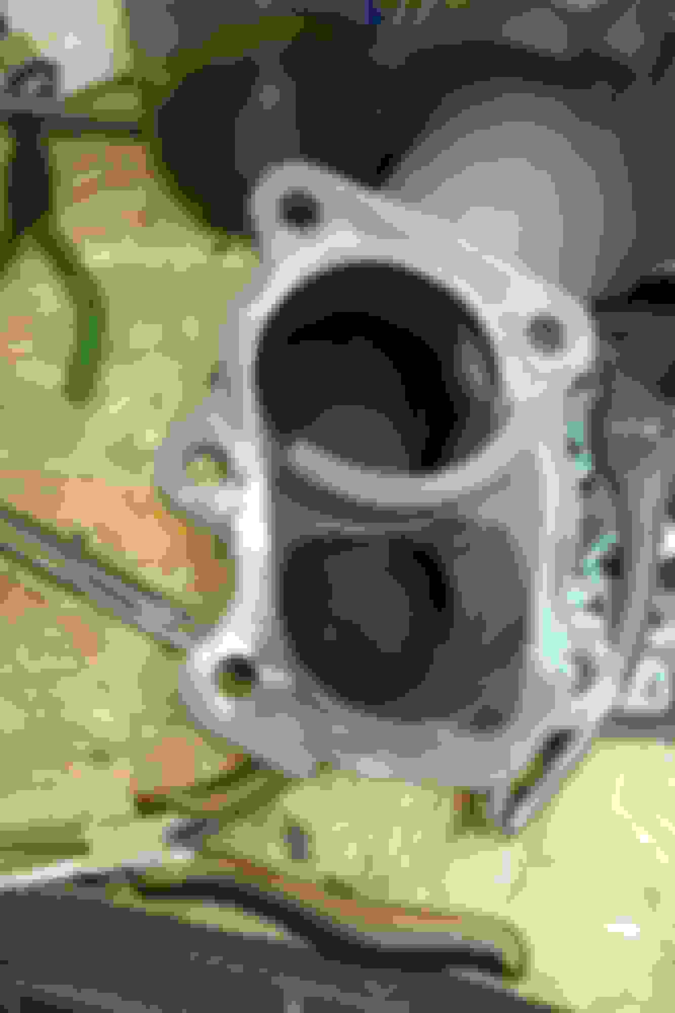
But now that I've got my turbo off, I can see that it isn't the turbine design from ATP that I thought it was... The housing on there has no internal divider, whereas this has one and the FM2 DP is cut to accommodate this.
I'm going to open the bend between the turbine flange and the WG port and also open up the hole, though note how off-center the flapper is! The hole is ~23mm (will take a better measurement tomorrow). I'll try and open the diameter as much as I think is safe to do, though it looks like 3mm+ should be achievable.
One other question though, based off the soot marks, the FM2 downpipe really doesn't look to line up well with the edges of the IWG. Does anyone think this is worth porting? The turbine exit looks fairly well matched, but the IWG much less so....
I also took a bit out of the area where the divider is. And go back to the first page and see that i took down all those bumps and ridges that create turbulence (maybe). I also did some work to the coldside and work on the log manifold.
I also took a bit out of the area where the divider is. And go back to the first page and see that i took down all those bumps and ridges that create turbulence (maybe). I also did some work to the coldside and work on the log manifold.
Thank you for the pictures. It looks like your turbo matched up to your DP a lot nicer than mine!
Were you able to measure any differences with that porting? I hadn't thought of doing that much, but I will.
Seat of the pants says it spools faster. But i really have no idea.
This port job didn't last long. I was on the stock engine when i did this, It wasn't long when i went built engine and things got crazy very quickly. Every time the car went out during the "building" stages the tune was being optimized. So any gains or losses could just have been tune changes.
I know the feeling when things keep getting out of hand quickly. I'll post my findings up here (along with some pictures) as I progress. I'd be happy with it only creeping to 12psi, but any other benefits would be a good plus!
Yep, that looks like mine. Ultimately, 17-18psi low boost might work, but I'd like EGT feedback to be able to dial back the boost duty if things get a bit hot (especially if I go to the Autobahn and go for Vmax...) and I'd like to keep boost by TPS.


 0
0