
LC-1 hook up to EMB w/ Autotune


Just want to make sure if the value I put for my programable LC-1 is correct to Simulate NB going to the AutoTune (brown wire).
1) I am going to use Analog #1 out to the AutoTune (brown wire).
What Value should I be programming to simulate NB: 0V = ?
1V = ?
2) I am going to use Analog #2 out to Monitor with an Autometer NB gauge.
What Value should I be programming to simulate NB: 0V = 18:1 ?
1V = 9:1 ?
3) Advance setting- Anything I need to change? Respond time?
4) Wiring in the unit.
RED 12V - ECU Pin power 1B
BLUE Heater Ground - Engine Block near to ECU ground.
WHITE System Ground - Engine Block near to ECU ground.
YELLOW Analog 1 - Simulate NB to Autotune Brown Wire
Brown Analog 2 - NB gauge monitoring
GREEN Analog Ground - ECU Pin Ground 2B
BLACK Caliberation - NA
If anyone find any information I just put up distrubing.. Speak out! Thanks!!
Reply
 0
0

0


Joined: Sep 2005
Posts: 34,433
Total Cats: 7,549
From: Chicago. (The less-murder part.)
1) I am going to use Analog #1 out to the AutoTune (brown wire).
What Value should I be programming to simulate NB: 0V = ?
1V = ?
What Value should I be programming to simulate NB: 0V = ?
1V = ?
2) I am going to use Analog #2 out to Monitor with an Autometer NB gauge. What Value should I be programming to simulate NB: 0V = 18:1 ?
1V = 9:1 ?
1V = 9:1 ?
4) Wiring in the unit.
RED 12V - ECU Pin power 1B
BLUE Heater Ground - Engine Block near to ECU ground.
WHITE System Ground - Engine Block near to ECU ground.
YELLOW Analog 1 - Simulate NB to Autotune Brown Wire
Brown Analog 2 - NB gauge monitoring
GREEN Analog Ground - ECU Pin Ground 2B
BLACK Caliberation - NA
RED 12V - ECU Pin power 1B
BLUE Heater Ground - Engine Block near to ECU ground.
WHITE System Ground - Engine Block near to ECU ground.
YELLOW Analog 1 - Simulate NB to Autotune Brown Wire
Brown Analog 2 - NB gauge monitoring
GREEN Analog Ground - ECU Pin Ground 2B
BLACK Caliberation - NA
Reply
0
0
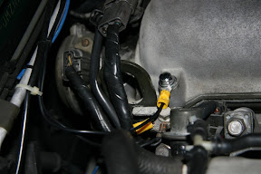
Is this the correct engine Ground for the LC-1 ??
1) for heater ground.
2) for system ground, on the same bolt with ECU ground.
3) I've ground the Analog ground to the 2B ECU pin.
1) for heater ground.
2) for system ground, on the same bolt with ECU ground.
3) I've ground the Analog ground to the 2B ECU pin.
Reply
0
0

Thread
Thread Starter
Forum
Replies
Last Post


