
NB Cam Angle Sensor Heatsoak/Failure

Elite Member

Joined: Mar 2007
Posts: 5,285
Total Cats: 883
From: Santa Clara, CA
It does use the double tooth to gain initial sync, so I'm surprised it actually starts if it's consistently only getting one pulse. Perhaps at cranking speeds the two pulses work properly? Does it work if you key off/on while the car is rolling?
Inspecting the code, it could be a lot more paranoid in the sync check than it actually is, because it totally ignores any cam teeth that show up in the intervals when it isn't expecting them.
--Ian
Reply
 0
0

0
I *believe* it won't advance the second tooth right out - but certainly with the 36-2 set up I have, it's easy to cross tooth boundaries. Then again, since they are just looking for the missing teeth, it's easy to capture them - and I STRONGLY suspect that's why VVT's possible at all - that they only look for the tooth to be once per rev.
Not counting a missing double seems like bad news, but I noticed this myself (though not formally) that I rarely get the "got single tooth when expecting 2" error.
It's odd since they have an OPTION for ignoring out of place teeth, but it seems to do it all the time anyway. I choose my battles with those guys, though, so learning how to make it work like they say it does is generally light years ahead of trying to get it genuinely fixed.
Short version: Use the OEM sensor if you have VVT. I'll see if I can figure out why it misses later.
Reply
0
0

Elite Member
Joined: Mar 2007
Posts: 5,285
Total Cats: 883
From: Santa Clara, CA
OK, 36-2 is a totally different code block from the standard 4-tooth NB wheel, so nothing of what I said applies to it. 
Looking at the 36-2 code, though (SPKMODE55) it appears to have a semi-sync'd mode in which it operates as "WCOP" (waste coil-on-plug). Perhaps with the other sensor it starts up in that mode and never comes out?
--Ian
Looking at the 36-2 code, though (SPKMODE55) it appears to have a semi-sync'd mode in which it operates as "WCOP" (waste coil-on-plug). Perhaps with the other sensor it starts up in that mode and never comes out?
--Ian
Reply
0
0
Yeah - totally possible. And it makes sense, cause it DID run. It's just annoying it didn't set a code. I remember years ago working on my inputs and they got it "working" in software, but now it's hard to tell when the hardware's right - and stuff firing when there's bad info is scary and costly.
It certainly could just keep "resetting" into semi-seq.
It certainly could just keep "resetting" into semi-seq.
Reply
0
0
Ok, I have lots of oscilloscope captures, but here's what you need to know:
1) OEM sensor. People have trouble cooking these. They are powered off +12V. While it seems to be sensitive to allignment, basically it either works or it doesn't. If you're WAY too close and way too slow, it'll stick so the signal will look inverted.
2) Evo10 sensor - don't use. It's a curious beast which seems to output a 3.3v square wave, but it only goes down about halfway (2.2V abs). Pull ups just shift the resultant wave upwards. It seems to miss the second tooth as well (see next section) when too close.
3) Evo8 sensor. This one has some potential. It's very clean. The trouble is on the VVT cams it doesn't see the gap between first and second tooth.
On a '99 cam gear, I get the missing tooth... until I increase the gap to >~0.75mm (0.030"). Pull up to +5 or +12 doesn't seem to change anything, though without a pull up there is no output.
I feel that this would be a very worthwhile upgrade for someone running a 99 on an MS or something. I'm not sure if the OEM computer could use it if properly spaced out, though I strongly suspect it could and would be reliable.
My feeling is to knock the ring with the teeth off the VVT cam - it's easy to do. Trim off what you don't want and be happy about it.
This leaves you two options:
1) Knock off two teeth, then with one tooth any generic set up will work nicely on MS. This is probably the single smartest way to go.
2) To keep that "stock intent" you could probably grind away a fraction of the two teeth in the doublet to create a bigger, more visible gap. This would probably work but I'm not sure what it gets you. At BEST you might get a tinsy bit more cam timing accuracy, but I'm not even sure this is the case.
If you run that sensor on an NB2, you'll get a semi-sequential sync and it will run - but it will assume the cam is at the min-cam-pos and just leave it there, uncontrolled. So I'm back on the OEM sensor (street driving this isn't an issue). I may try to make a custom toothed wheel, or just knock off the two I have.
Lastly: Given the timing ring is just kinda shoved on, perhaps there are differences motor to motor which is why there's offset issues with some people's VVT tables relative to others.
Reply
1
1


I don't really know, but while looking at the sensor, it goes into a little tube housing and I've seen that inside (online). Still, I assume that it is. I believe the right hand one is someone's home modification. The one on the right doesn't quite look like the other one modified, but it's hard to say. I don't really know the answer on that one.
Oh, I take it back. There's a different one on intake and exhaust! It looks like one of those is intake and one exhaust and I the more asymmetric one is the exhaust.
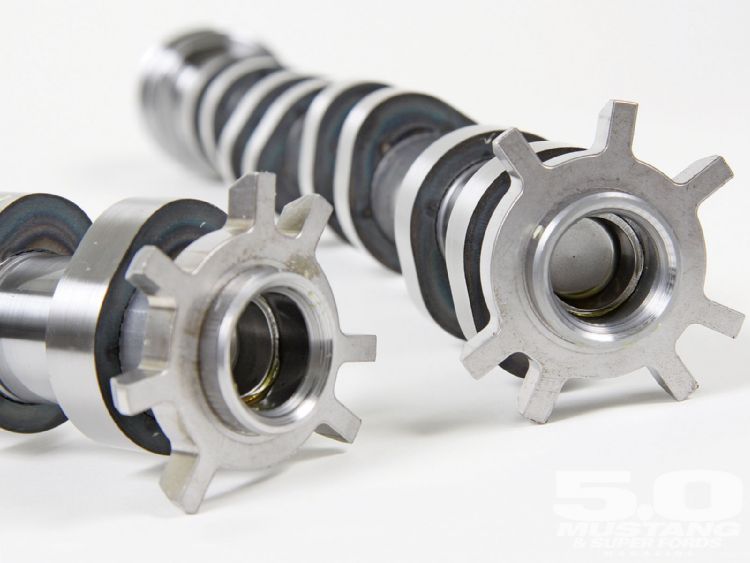
These are off some Ford, but I really like them - they give you a rapid rise and are the same style as our OEM ones.
The real question is for the MS folks - do more teeth buy you more resolution/accuracy in cam phasing? If not, one tooth will mean no special code and everything you could want (except perhaps slower starting? Depends on how they handle that now)
Oh, I take it back. There's a different one on intake and exhaust! It looks like one of those is intake and one exhaust and I the more asymmetric one is the exhaust.
These are off some Ford, but I really like them - they give you a rapid rise and are the same style as our OEM ones.
The real question is for the MS folks - do more teeth buy you more resolution/accuracy in cam phasing? If not, one tooth will mean no special code and everything you could want (except perhaps slower starting? Depends on how they handle that now)
Reply
0
0
Elite Member
Joined: Mar 2007
Posts: 5,285
Total Cats: 883
From: Santa Clara, CA
Reply
0
0
Ah! It might be that there's no good code for this IF you have the stock, asymmetric NB wheel (4 tooth). I don't know but I do strongly suspect.
I imagine any 36-1 wheel with a single toothed cam would be ok (I guess I can check into it, though I didn't see anything specific in the manual). I figure someone who's willing to take the camshaft out of the motor to grind off teeth could very easily change the crank trigger wheel - either for a high end damper/trigger combination (such as 949 or FM sell), or the DIY protege wheel.
If 36-2 + 1 works, that's actually very simple to achieve. Perhaps we can con Emilio into making a single tooth cam wheel.
Alternatively, there's the DIYAutoTune cam sensor, but as yet I don't know if there's any solid reliability information on it. I've yet to get a scope on one to see if it's as clean as the Evo8.
Well, now that I have a spare ring, I may lop off some teeth and see how it works.
Reply
0
0

Reply
0
0

Joined: Sep 2005
Posts: 34,381
Total Cats: 7,504
From: Chicago. (The less-murder part.)
An interesting and potentially relevant note was recently posted in This Thread.
Matt later confirmed that this did fix his problem.
Interesting side not...
We are working on the ME221 based PnP for the MX5 NB - We use the Max9926 as our input conditioner - currently we are seeing the crank signal 'dissapear' at around 2000rpm then come back, then go again (at around 500mS interval on the logic analsyer). I am putting this down to the fact we are use 470ohm pull-ups to 5v as opposed to 3k3 (as per OEM) so I suspect the sensor is overheating or something to that effect - going to try 3k3 today and will report back Maybe helpful for those who have had this issue (if any!)
Matt
We are working on the ME221 based PnP for the MX5 NB - We use the Max9926 as our input conditioner - currently we are seeing the crank signal 'dissapear' at around 2000rpm then come back, then go again (at around 500mS interval on the logic analsyer). I am putting this down to the fact we are use 470ohm pull-ups to 5v as opposed to 3k3 (as per OEM) so I suspect the sensor is overheating or something to that effect - going to try 3k3 today and will report back
Maybe helpful for those who have had this issue (if any!)Matt
Reply
0
0

I'm Miserable!
Joined: Jul 2015
Posts: 60
Total Cats: 0
Indeed - even further Joe - my testing shows 3k3 allowws it to rev to 4000rpm and then the sensor drops - I upped to 10k pullups and it revs to 6200rpm now - going to change to 33K and give that a go... definately sensor heating/hold off
On the technical front, we are using MAX9926 into the +ve input (10K input resistors, -ve left floating, IC in operating mode A2, 5V pullups Of course its an ME221, not a megasquirt, but 'after the MAX9926 doesent matter what MCU it goes to
Matt
On the technical front, we are using MAX9926 into the +ve input (10K input resistors, -ve left floating, IC in operating mode A2, 5V pullups Of course its an ME221, not a megasquirt, but 'after the MAX9926 doesent matter what MCU it goes to
Matt
Reply
0
0
I'm becoming less and less of a fan of lots of filtering in front of this chip. For true VR, some makes some sense, but the real problem is the OEM sensor - it pulls down to 2.2V, it's hard to make the 2.2 vs 2.5V call, you know?
I tried pulling up to 5V (w/ 1k) and didn't seem any better, so I just stick with 12.
I'm curious for more details on Matt's issue - it could be overheating, if it's taking time, but it's also possible that it's open collector just plain can't handle the current to pull down 470. If they have a 200 (effective) ohm path to ground you're going to get a terrible signal. The alternate sensor I'm trying easily pulls it down.
Or, looking at it another way, 470 ohms on 5 V is 10 mA or some 50 mW. Probably more like 100 ohms for 1/4W.
Either way, big without too big is what the ladies ask for.
Reply
0
0
Joined: Sep 2005
Posts: 34,381
Total Cats: 7,504
From: Chicago. (The less-murder part.)
Really high.
As in "this is something other than the normal forward voltage across a semiconductor" high.
While you're in an experimenting mood, I'd be hugely curious to know, with a 5v pullup, whether the "on" voltage remains constant regardless of pullup resistance, or if lower "on" voltages are seen with higher pullup resistances.
Reply
0
0
That does sound like the sort of test one could run on a 1 figure budget. :-)
I wanted to check a few of those numbers again anyway. Similarly, if the OEM unit pulls down proportionately lower with a 5V pull up.
I wanted to check a few of those numbers again anyway. Similarly, if the OEM unit pulls down proportionately lower with a 5V pull up.
Reply
0
0


