
wiring an NA igniter not using a miata harness


Thread Starter
Senior Member
Joined: Jan 2011
Posts: 608
Total Cats: 172
From: sacramento ,ca
im working on a project with a turbo bp in it and im having trouble finding a diagram that shows how to wire the igniter and coils without using the stock miata harness. im using MS1 v3.0
Reply
 0
0

0


Joined: Sep 2005
Posts: 34,402
Total Cats: 7,523
From: Chicago. (The less-murder part.)
I assume you're working with a 1.6 ('90-'93) as the 1.8 NAs didn't use a separate igniter.
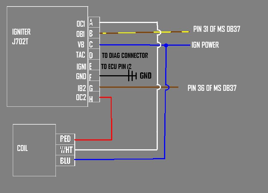
From the ECH, brown and brown / yellow are the triggers, +5 active-high. Black / white is "IGf", which is a confirmation going back to the ECU that the coil primaries are pulling current. Also active-high, though it may be +12 instead of +5 (can't recall.)
Between the igniter and the coilpack, white and red are the two coil primaries.
At the coils and igniter, blue (L) is +12.
Between the igniter and tech, yellow / blue is the tack drive signal. It's a +12 squarewave, active-high, whenever either coil is dwelling. (Basically identical to IGf)
So, all you need to do is supply +12 to the coils and igniter on the blue wire, and provide two active-high outputs from the BS to the brown and brown / yellow wires. Follow the 4G63 instructions, or do the following if you want it to be more reliable: https://www.miataturbo.net/megasquirt-18/better-spark-out-circuit-33964/
Reply
0
0
Joined: Sep 2005
Posts: 34,402
Total Cats: 7,523
From: Chicago. (The less-murder part.)
I didn't bring my whole car with me here in the cabin of this airplane to double-check, however it does appear to me that you've got it correct.
You may need to apply an external pullup to the tach and/of IGf pins in order for them to do anything useful (Some folks have reported needing to do this, others not.) 12v through 1k is typical.
The triggers from the ECU to the igniter are +5 active-high, requiring a fair amount of current to trigger reliably. We typically do 5v through 200-300 ohms. The older build threads say to use 5v through 1k for the triggers, but we've found this to be more reliable.
Reply
0
0

Thread
Thread Starter
Forum
Replies
Last Post


