

Double Check My Coolant Reroute Plan

Thread Starter


Joined: Apr 2014
Posts: 18,643
Total Cats: 1,870
From: Beaverton, USA
I've to a 1990 1.6 and have a planned DIY coolant reroute. Let me know if you see anything wrong with this as is.
Remove and block off front water neck with Begi Block off plate (keep fan relay sensor)
Put the 1.6 water neck in the back of the block and use a 90 degree fitting to take water from where the fan relay sensor was and send it to the heater core.
Inline thermostat in between the 1.6 water neck and the radiator.
Move the ECU CLT sensor to the unused port on the head underneath the ignition coils.
My only worry is that the sensor port in the 1.6 water neck won't flow enough coolant to the heater core.
Reply
 0
0

0

Reply
0
0

Junior Member
Joined: Jan 2014
Posts: 79
Total Cats: -9
From: Finland
LOL.
Did it ever occur to you that the flow to the heater core and back to the mixing manifold happens pre-thermostat so it is full time? That's how we circulate water in the block during warmup. Your plan eliminates this "feature."
Quit cheaping out. Just buy the BEGI adapter and KIA waterneck already.
Did it ever occur to you that the flow to the heater core and back to the mixing manifold happens pre-thermostat so it is full time? That's how we circulate water in the block during warmup. Your plan eliminates this "feature."
Quit cheaping out. Just buy the BEGI adapter and KIA waterneck already.
Reply
0
0

he doesn't plan to eliminate the flow.
he clearly states that he's going to use the existing port for the coolant sensor to send to the heater core and wants to know if it's too small.
he clearly states that he's going to use the existing port for the coolant sensor to send to the heater core and wants to know if it's too small.
Reply
0
0
Thread Starter
Joined: Apr 2014
Posts: 18,643
Total Cats: 1,870
From: Beaverton, USA
Reply
0
0
I misread. Thought you were planning to put the stat in the waterneck. It was early.
Should work, but you'll have to tell us how the heat works out. I can tell you that with the begi spacer, heater output is pretty diminished compared to oem. That's a 3/8npt (0.375"ID) port offset from the main flow by 90 degrees.
Should work, but you'll have to tell us how the heat works out. I can tell you that with the begi spacer, heater output is pretty diminished compared to oem. That's a 3/8npt (0.375"ID) port offset from the main flow by 90 degrees.
Reply
0
0
Thread Starter
Joined: Apr 2014
Posts: 18,643
Total Cats: 1,870
From: Beaverton, USA
Well the fan sensor port is inline with the flow so that should help some. But a 90 degree adaptor might hinder it. I can always modify the 1.6 waterneck if its not working out. I was thinking about grafting on the current water neck that goes to the heater and have a weird double ended water neck.
But other than diminishing heat am I risking anything by using the smaller port?
Also am I correct about the ability to use the port in the head for the ecu CLT sensor?
But other than diminishing heat am I risking anything by using the smaller port?
Also am I correct about the ability to use the port in the head for the ecu CLT sensor?
Reply
0
0
You should be fine during warmup circulating coolant through that port. And putting the ECU CLT sensor into the head should work so long as they are the right threads. The ECU CLT sensor has straight rather than tapered threads. It needs a copper crush washer to seal. Most existing holes in the head are a tapered pipe thread, so just be careful.
Reply
0
0
Thread Starter
Joined: Apr 2014
Posts: 18,643
Total Cats: 1,870
From: Beaverton, USA
You should be fine during warmup circulating coolant through that port. And putting the ECU CLT sensor into the head should work so long as they are the right threads. The ECU CLT sensor has straight rather than tapered threads. It needs a copper crush washer to seal. Most existing holes in the head are a tapered pipe thread, so just be careful.
Reply
0
0

Not sure if the right thread, but probably is. Might interfere with the waterneck though. Worth a shot.
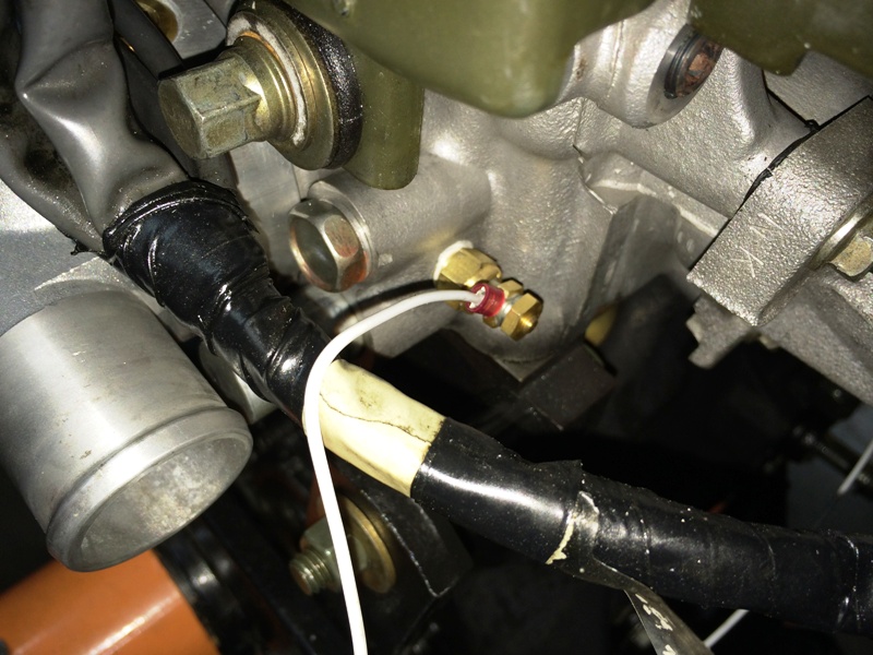
Head is easy to drill and tap. You can see in the picture where I added a 1/8"NPT hole for an aftermarket temperature sensor.
Reply
0
0
Thread Starter
Joined: Apr 2014
Posts: 18,643
Total Cats: 1,870
From: Beaverton, USA
So I guess if the hole that is already there doesn't work I can always just drill and tap a new hole for the sensor. I think this way should work and will only cost me about 40 bucks.
Reply
0
0
Thread Starter
Joined: Apr 2014
Posts: 18,643
Total Cats: 1,870
From: Beaverton, USA
Ugh, sometimes I'm an idiot, I had been looking at pictures of a 1.8 head, I have a 1.6 head.
So now I'm looking at this picture and my idea won't work. Oh well back to the drawing board.
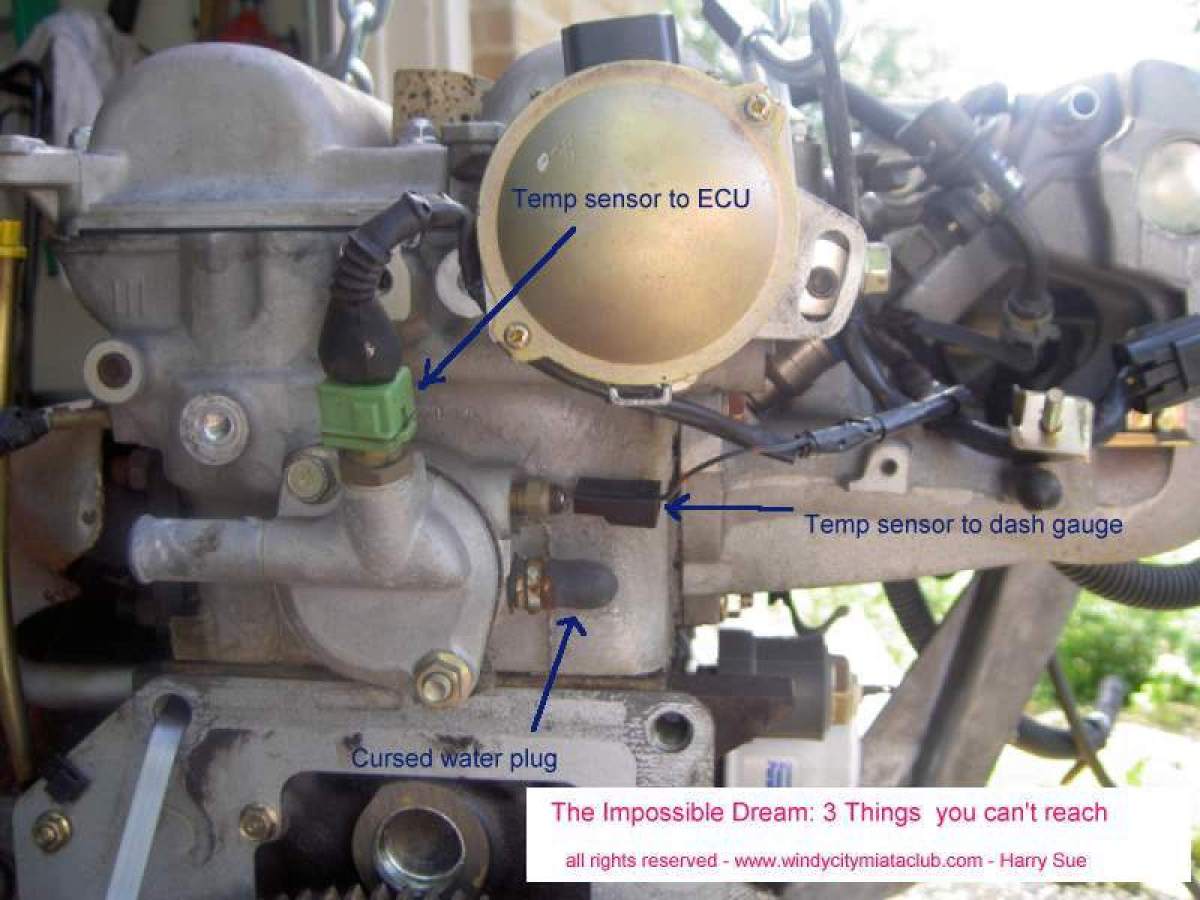
So now I'm looking at this picture and my idea won't work. Oh well back to the drawing board.
Reply
0
0
Thread Starter
Joined: Apr 2014
Posts: 18,643
Total Cats: 1,870
From: Beaverton, USA
Idea 2.
Move ECU temp sensor to the front where the current fan sensor is and use MegaSquirt to turn on the fans.
Objections?
Move ECU temp sensor to the front where the current fan sensor is and use MegaSquirt to turn on the fans.
Objections?
Reply
0
0
Thread Starter
Joined: Apr 2014
Posts: 18,643
Total Cats: 1,870
From: Beaverton, USA
Alright I'm more just writing ideas down for myself now. But I think 2 works the best. I get heater feed out of the old fan sensor port. I drill a hole in the inline thermostat to keep water flowing when closed. I plug the front water neck with A plate tapped for the ecu sensor (does anyone know if the fan and ecu sensor are the same threads?) And then I'm done.
For my own record:
3/8 NPT tap for front waterneck
3/8 NPT 90*
3/8 NPT to 5/8 barb for heater hose: http://www.bellengineering.net/produ...roducts_id=593
For my own record:
3/8 NPT tap for front waterneck
3/8 NPT 90*
3/8 NPT to 5/8 barb for heater hose: http://www.bellengineering.net/produ...roducts_id=593
Reply
0
0

One temp sensor at the rear of the head (in the major coolant flow) and use MS to control the rest.
Reply
0
0
Thread Starter
Joined: Apr 2014
Posts: 18,643
Total Cats: 1,870
From: Beaverton, USA
Reply
0
0


