When you click on links to various merchants on this site and make a purchase, this can result in this site earning a commission. Affiliate programs and affiliations include, but are not limited to, the eBay Partner Network.
On relieving crankcase pressure, PCVs, catch cans, breathers and whatnot...
The purpose of this thread is throwing an unorthodox idea on your screen to get your opinion on mine.
Crankcase pressure and the associated condiments that pressure (and flow it generates) in the form of gases, vapors and outright liquid oil in force induction engines have been discussed here, with no definitive results to this day.
I read (and re-read) pretty much all posts covering that topic, and it seems there are several approaches producing various results in individual engine setups.
My car has been FI for almost 12 years now. I had a supercharger for about 10 years, and there is an "R2S" progressive twin turbo setup under my hood as we speak.
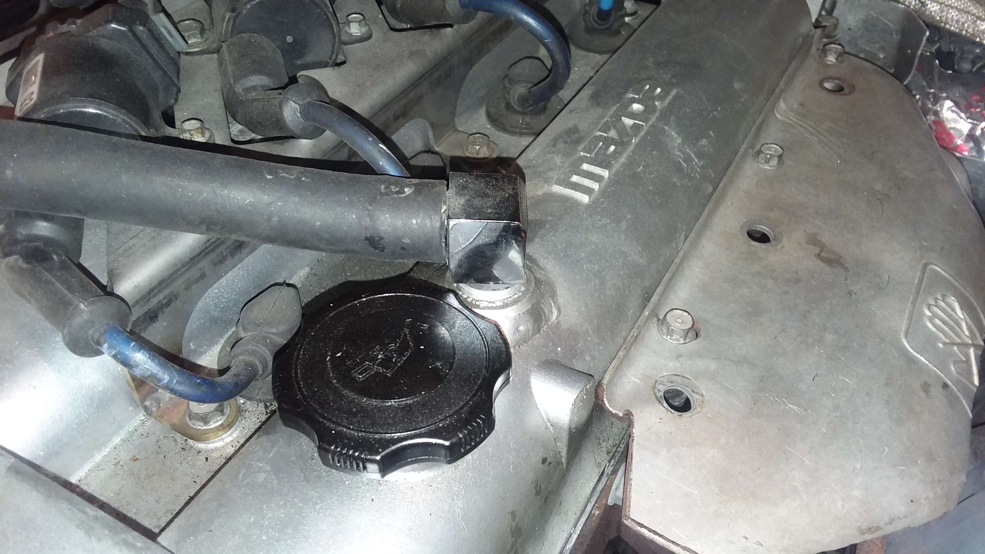
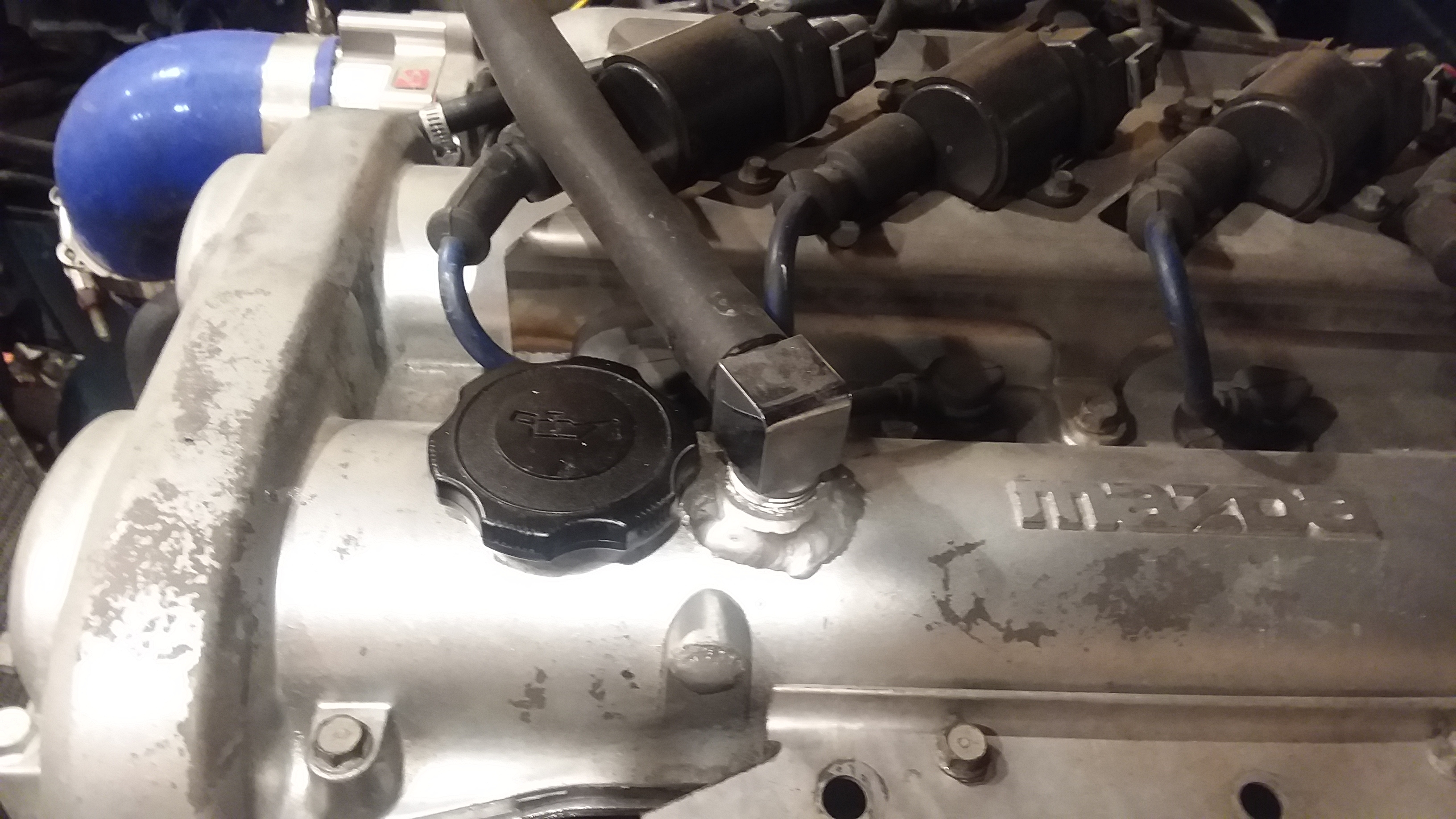
I have a "GTX" PCV, plus a check valve in line with that on the cold (IM) side, and a filter (VTA) on the passenger side port.
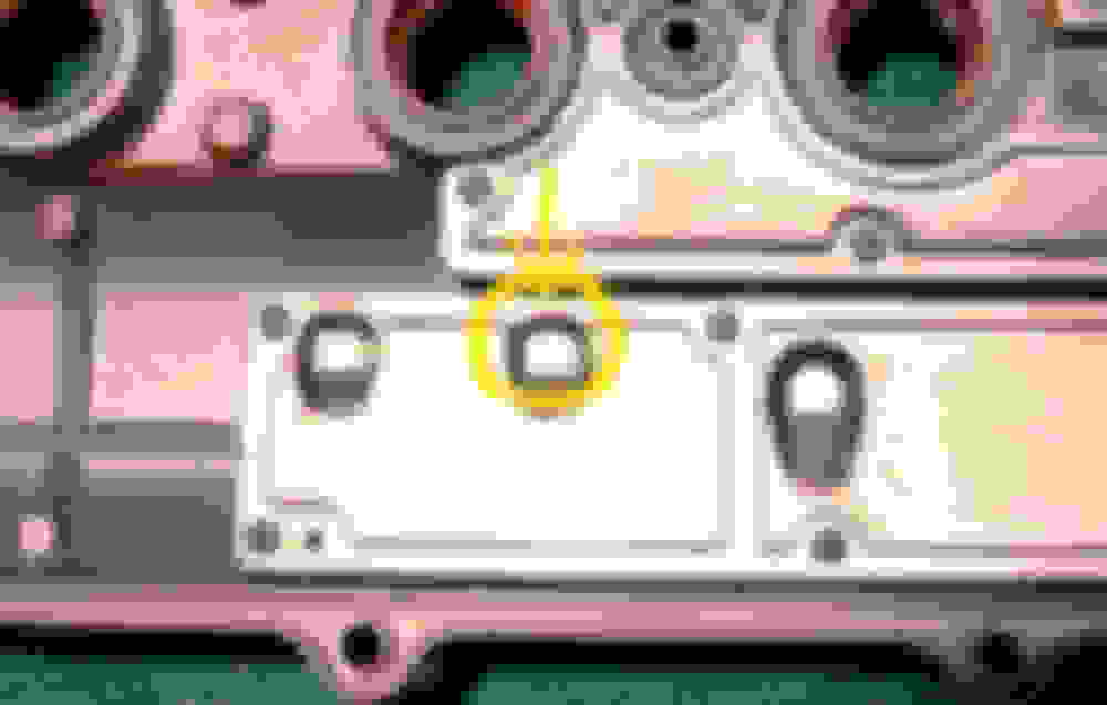
Baffles in the valve cover have steel wool mesh in them, the port between the center and passenger side baffles is enlarged to 10 mm, and I also drilled a small hole in the baffle cover as shown in the pic below:
This system worked like a charm for years.
Until, that is, I got on the 5.3 km F1 track in Istanbul at 18.5 psi. My engine bay was covered in oil that day.
It never puked oil out of the breather filter after that.
Things were great till I finished my engine break in with the turbo setup. (I had rebuilt the engine during the turbo install, hence the break in)
I saw plenty of boost during that period, but not sustained high RPMs. The thing pulls like a freight train from ANY rpm. (I saw 21 psi at just over 2000 RPM once while I was setting up my EBC...)
Now that the break in is over, I am blowing out copious amounts of oil out of the passenger side vent from the valve cover.
(I know my active hood vent right over the turbos works perfectly well, because the oil smoke from the hot manifold shoots straight up, and the car looks like a friggin' steam locomotive on the freeway...)
OK, here is my idea:
Crankcase pressure is inevitable. And, it happens downstairs, below the pistons, where the action is.
So, why are we trying to relieve it from the top of the engine and allowing it to carry all that nastiness up the drain galleries to the valve cover?
Why can't this pressure be relieved at the source, meaning, from the oil pan itself?
I can drill a large hole (3/4" diameter) close to the front of the oil pan (think of the turbo oil drain location, but on the driver's side), weld an elbow to that hole pointing up and slightly towards the rear, and clamp a 3/4" ID oil resistant hi-temp hose on it and bring it up underneath the intake manifold towards the back, all the way up past the valve cover level, to the back.
Bringing the end of the hose that high would eliminate the possibility of oil sloshing out under heavy braking.
The large ID would keep the oil from percolating up with pressure: oil would break up and fall back because of the large diameter, and just vapors and pressure would go up.
I would have a container with steel wool at the end of the hose, that container would be fixed to the firewall (or the IM) with a bracket and a breather filter would adorn the said container.
Such a setup would allow the inside of the valve cover to be nice and calm, with no violent flow to carry crap all over the place.
What do you think?
I will pull the engine and drill the oil pan in a heartbeat if you guys think this is a viable solution.
I'm no expert here but from what I understand the use of the rocker cover to vent is as simple as the gases rise, and fluids fall.
So venting the cover means it's mostly gas being vented, with a bit of liquid that's atomised from being flung around by the cams etc.
If you wanted to cheaply and quickly test your idea, why not just pull the dipstick out and use the dipstick tube as a temporary vent to check what sort of pressure is escaping there?
I see your point, but...
* using the valve cover means an easier and cheaper route for the factory,
* gases will still rise with the system I am thinking of, allowing liquids to "fall" in a large diameter vent rising from the oil pan, as well.
* rapidly rising gases through smallish diameter drain galleries within the engine impedes the flow of oil down from the head, causing pooling there
* oil being flung around by the camshafts is really nothing compared to the mess the crank and pistons are making downstairs - the cams have much smaller protrusions and they spin at half the speed of the crankshaft. Ergo, mist in the valve cover will be much easier to deal with, and oil will be able to flow down to the pan with no resistance.
I really like your idea of testing this approach using the dipstick. My only concern is the small ID, coupled with the fact that the bottom end of the dipstick is a little too close to the oil level in the pan - oil that is forced to the back of the pan under heavy acceleration may flow up the dipstick tube...
(I could always install my gopro with the underwater housing under the hood on the passenger side to see what is going on.)
For most of the history of telephony, placing long-distance phone calls was costly. And "long distance" generally meant to a distant point on the same continent. Last night, after receiving a message from Hakan, I placed a phone call* to Turkey, to a man who I have never met in person, and we chatted for around two hours. First about this specific idea, then about cars, economics, social and political ideologies, tea, and finally about this specific project again.
* = it was a call, and I used my phone to place it, so the fact that the traditional "telephone system" per se was not used is not germane. It was a phone call.
Hakan asked me if he was crazy. I replied that, yes, he is clearly crazy, however this specific idea didn't factor into my reaching that conclusion.
The basic idea seems reasonable to me. The gasses which we are all venting from the valve cover didn't originate up in the valve cover, they originated down in the crankcase. So why not ventilate the crankcase itself?
I have utterly no idea where liquid oil tends to be during engine operation. If, in fact, it does tend to slosh up around the sides of the oil pan towards the front during periods of high engine load (when blowby gasses are being produced), then such a design will likely result in lots of liquid oil being blown upwards into the catch can.
(It would be interesting to see the results of a small camera (and light source) placed inside the crankcase during an AutoX lap.)
But my bet is that this is only going to happen when you're on the brakes, off the throttle, and under vacuum. Sure, some oil will reach the welded fitting at the top of the oil pan during braking, but given that Hakan is specifically focusing on a large-diameter fitting, followed by a long, large-diameter, nearly vertical hose up from that location to the catch tank, I'm having a hard time visualizing any significant amount of liquid oil being raised up to that level.
I could be totally wrong. But I've learned over the years that when Hakan gets a wild idea, it's generally good to encourage it. After all, this is a guy who says "I'll just pull the engine" in the same way that people with wet socks might say "I'll just change my socks."
Last edited by Joe Perez; May 5, 2019 at 12:04 PM.
* oil being flung around by the camshafts is really nothing compared to the mess the crank and pistons are making downstairs - the cams have much smaller protrusions and they spin at half the speed of the crankshaft. Ergo, mist in the valve cover will be much easier to deal with, and oil will be able to flow down to the pan with no resistance.
Having re-read this, it occurs to me that you have identified a potential problem in the design.
By placing the ventilation port in the valve cover, the OEM design takes advantage of the natural fact that, by being forced to travel up through the oil drain passage from the crankcase into the area above the head, some of the atomized oil being carried upwards by the blowby gasses will naturally tend to collide with the wall of the passage, and condense.
And, as you have astutely observed in the photographs in the first post, there is an additional series of chambers within the valve cover to encourage further condensation of atomized / vaporized oil.
In your proposed design, this will all have to occur within the catch tank at the top. Making it as large as possible, and as internally complex as possible (eg: by stainless mesh sponge material), should be prioritized.
Cooler temps is a requisite factor for condensation, and internal engine galleries are far from cool for that to happen.
That's why everything and the kitchen sink travels up to the head with blowby gases.
If you evacuate the said gases from the pan, any external routing will be much cooler than the engine internals, making it easier to condense and separate oil, water and fuel from each other.
I may have forgotten to clear something up, too.
I will not remove the PCV, the check valve installed inline with it and the breather filter on the exhaust side of the valve cover.
They will keep venting whatever vapor is being generated on top of the cylinder head.
I could take this thing as far as designing an elaborate baffle system high on the firewall to remove all liquids, and then route the remaining vapor into the downpipe via a slash cut / venturi setup.
The upside of such a solution is having no oily mist on the engine bay surfaces...
Guys, we are always told to think out of the box, so I went out for a smoke break. (all puns are literally, deliberately and insistently intended)
All I need is your input.
I may have forgotten to clear something up, too.
I will not remove the PCV, the check valve installed inline with it and the breather filter on the exhaust side of the valve cover.
They will keep venting whatever vapor is being generated on top of the cylinder head.
Only under limited conditions is there flow from the Valve Cover to the Intake Manifold via the PVC connection.
Only under limited conditions is there flow from the Valve Cover to the Intake Manifold via the PVC connection.
And yet, the car spends almost 90% of its running hours in those conditions.
There are times when you just cruise for hours with short bursts of boost in between.
You have truly done some amazing engineering in your car but in this case there is no need to reinvent the wheel.
You are at roughly three times the original horsepower planned by the engineers that designed the engine. In general terms you are making three times the cylinder pressure and likely three times the blowby volume and it needs to be dissipated. Trying to do that through the small single hotside vent is futile. The PCV valve is closed during boost (which is when we need most venting) so it is completely useless.
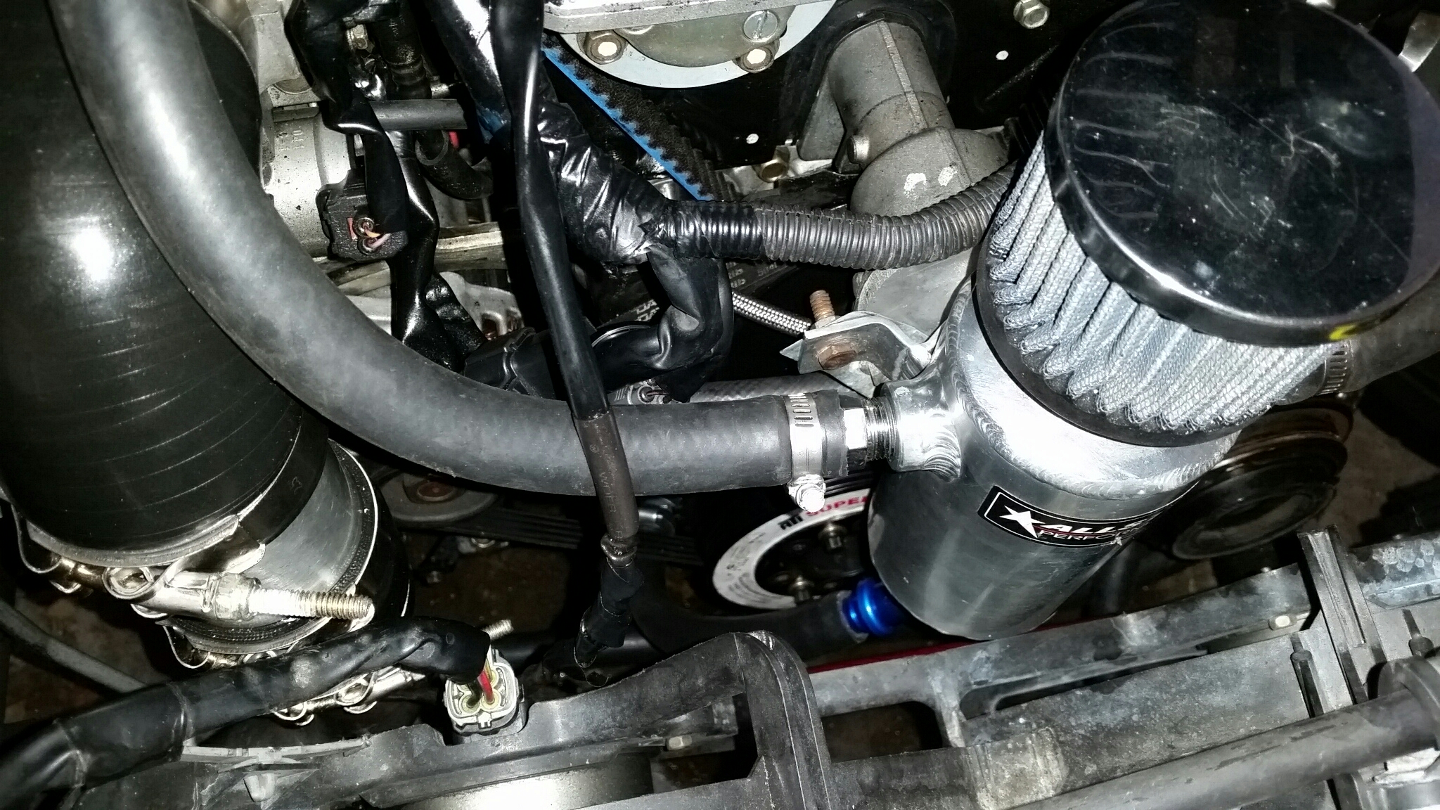
What I have done was simple and works fine. I opened up the interior passage from the center to the coldside of the valvecover. I had a 1/2 inch NPT threaded bung welded in to replace the PCV grommet and had another welded into the top of the hotside of the valve cover. The tiny original hotside nipple was removed and the little hole welded shut. Both the hot and cold side vents are attached by 5/8 inch hoses to a baffled, vented catch can. There is a small quantity of metal mesh filter media in the valve cover galleries for added surface area but I'm not sure they were necessary. Simply increasing the diameter of all of the orifices slows the blowby vapors enough that the oil falls out of suspension and is no longer propelled out of the engine. It simply drains back. The catch can is receiving roughly a teaspoon of oil and moisture each full trackday at over 300whp.
Think of it as the difference between blowing over the top of a drinking straw in a cup of water and blowing over the cup of water without the drinking straw. One carries a lot of liquid and the other doesn't carry any at all. Velocity is the enemy. Make the orifices large and the airspeed slows down.
I would not attempt to evacuate crankcase vapors from the oil pan area because of the windage occurring there. The lower crankcase is a much more volatile place with much more liquid oil in suspension than in the upper valve cover. The only engine I know that vents from down there is the Austin A series engines and they did it while implementing a large filter canister on tiny, slow turning 48hp engines that were adapted from tractors. And since everything else was garbage on those from an engineering standpoint, I wouldn't follow them for inspiration.
Again, I'm no expert but it works flawlessly.
Last edited by sixshooter; May 6, 2019 at 07:37 AM.
I would not attempt to evacuate crankcase vapors from the oil pan area because of the windage occurring there. The lower crankcase is a much more volatile place with much more liquid oil in suspension than in the upper valve cover. The only engine I know that vents from down there is the Austin A series engines and they did it while implementing a large filter canister on tiny, slow turning 48hp engines that were adapted from tractors. And since everything else was garbage on those from an engineering standpoint, I wouldn't follow them for inspiration.
Actually the general fix for a highly developed A series engine is to weld two massive breather pipes (3/4") into the valve cover, reroute the output from the block to one and vent the other uphill to a large catch can... pretty much replicating the 'fix' for a BP. I think the block is a bad place to vent crank case pressure.
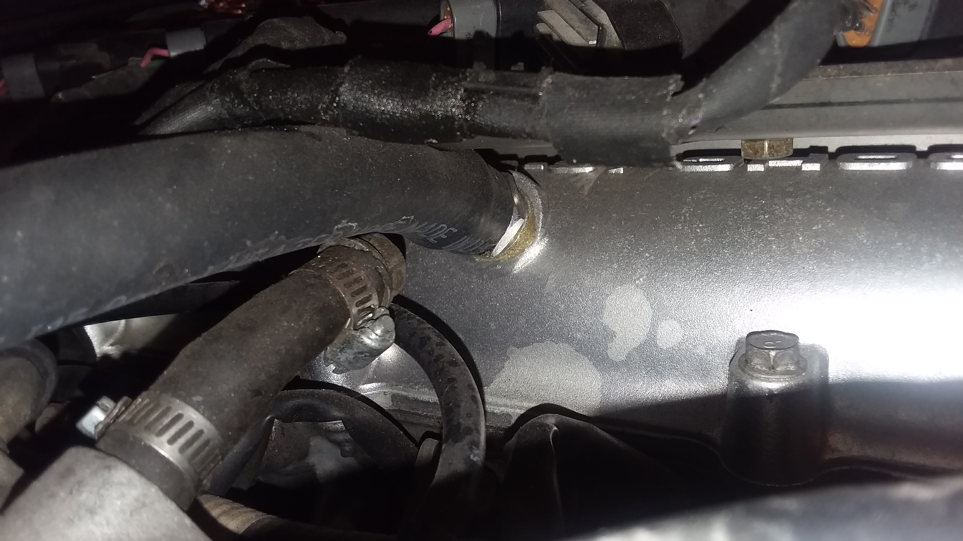
I recalled incorrectly. I did not use a welded in bung on the cold side. I simply tapped and added the fitting there. Several other guys on the forum local to me welded bungs on both sides. Ryan_G, Joker, and some others have done theirs this way and have pics in their build threads (IIRC). A welded bung was used on the hot side with a fitting. See pics.
Please ignore the mess. I have things apart right now but here is some idea what was done.
Last edited by sixshooter; May 6, 2019 at 08:04 AM.
I went back and looked. Ryan_G originally ordered 3/8 NPT bungs and we later drilled and opened them up to 1/2 NPT for larger fittings and hoses to solve his problems. https://www.miataturbo.net/build-thr...5/#post1386656
Steve, do you have elaborate compartments and baffling in your All-Star catch can?
Also, does it need to be mounted higher or lower than the valve cover level?
I have to ask, because there is just no room in my engine bay, so I need to make a custom container for whatever volume is available to me. It will be an interesting exercise in 3D modeling.
Sorry I missed your call. I was dealing with some issues related to a lightning strike at the home of my elderly parents and could not switch lines. Your call was listed as "PRIVATE NUMBER". Feel free to call again.
The catch cans are baffled internally. The design consists of the smaller tube that the Breather filter is attached to extending down into the body of the larger tube. Additionally there are 2 half moon plates welded within the inner tube. They are placed diametrically opposed one above the other so that the vapor has to make turns to climb out past them. The two Inlet bungs on the exterior are placed high up so that the vapor entering runs directly into the exterior of the inner tube. There is a petcock and drain at the bottom. Ryan ran his drain back to the front of the oil pan but I did not believe that to be a good idea because I did not want to reintroduce moisture to the oil.
I feel it is okay for the lines to run either upward or downward to the catch can as long as there is no pooling in a belly of the hose restricting free flow of air. My original location prior to the change to the BMW transmission was on the right side of the transmission tunnel.


 0
0