
More Oil Catch Can Contents

Thread Starter
Elite Member
iTrader: (2)
Joined: Jan 2009
Posts: 4,149
Total Cats: 230
From: Columbus, OH
I generally try to empty the catch can while I am filling up with gas, so this is what has accumulated in my catch can since the last fill-up. I was hoping I could get help identifying the contents, and perhaps diagnosing potential problems.
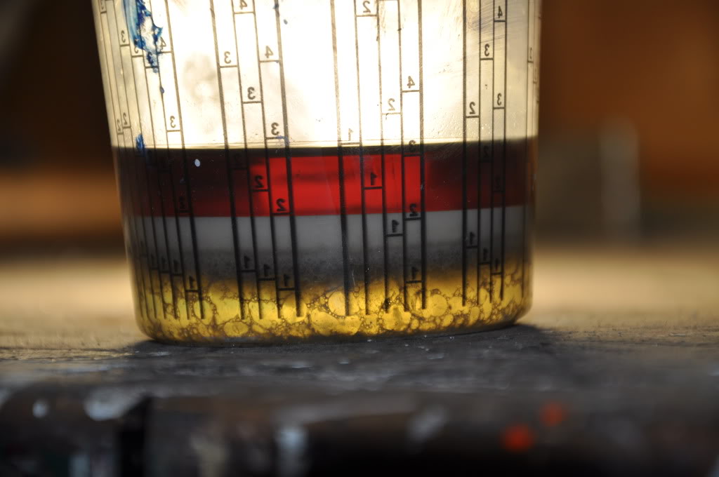
As you can see, there are 4 distinct layers in this suspension:
1. - Top 1/3rd - Solution - Translucent Red in appearance - Based on smell/feel this solution is primarily gasoline. Is this a product of running too rich?
2. - Third 1/6th - Colloid? - Opaque white in appearance - Is this an aerated water/oil mix?
3. - Fourth 1/6th - Colloid - Opaque dark grey in appearance - I'm assuming this is a water/oil mix?
4. - Bottom 1/3rd - Solution - Translucent Amber in appearance - I haven't actually stuck my finger into it, or taken any of it out, but based on density and color, I am assuming this solution is primarily water. Does this water condense out of the air during the compression stroke?
Reply
 0
0

0

You'll get the gasoline by condensing vapors from combustion chamber blow by. Thats the primary function of the vapor capture coming off the motor (PCV).
From a density stack position I would think you guessed right...
Gas 730 kg/m^3
Oil 880 kg/m^3
Water 1000 kg/m^3
They should stack up just like that.
This is a very cool picture!
From a density stack position I would think you guessed right...
Gas 730 kg/m^3
Oil 880 kg/m^3
Water 1000 kg/m^3
They should stack up just like that.
This is a very cool picture!
Reply
0
0


Elite Member

Joined: Jul 2005
Posts: 2,502
Total Cats: 146
From: Anacortes, WA
When I start it up on a 40 degree rainy day it fills up quickly with mostly water.
I've been thinking about trying to pull a small vacuum on it to suck moister out of the crank case. A good separator system a check valve and using the exhaust flow in the tail pipe to pull a vacuum on the crank case breather system would be the plan.
A friend of mine gained 18 hp on the dyno on his 250 hp civic by pulling a vacuum on the breather system using exhaust flow. A 5/8" pipe cut at 45 degrees welded into the tail pipe pulled a few inches of vacuum on the breather can. Sucks all the blow by out the tailpipe and makes the rings seal better.
Bob
Reply
0
0
That's phenomenal. I'd never guessed that a slash cut tube at the exhaust would make that much of a difference on that little hp. Where was the tube located in the exhaust? I'm guessing closer to the front- which would mean removing the cat for those so equipped.
Reply
0
0


Elite Member
Joined: Jul 2005
Posts: 2,502
Total Cats: 146
From: Anacortes, WA
http://www.summitracing.com/parts/SUM-120108/
I have also been considering electric pump idea. See post 17.
http://forums.corvetteforum.com/c4-f...-it-works.html
But the slash tube seems like a simpler less problematic solution. Instead of a breather filter on my catch can I would just run a -10 line out the top to a fitting in the exhaust after the O2 sensor bung, I�m thinking in the test pipe I have in place of the cat.
Bob
Reply
0
0

I'm Miserable!
Joined: Jun 2009
Posts: 1,866
Total Cats: 0
From: albany, ga
Yeah I"ve told others about using the exhaust to create a vacuum in the crankcase, people call me crazy, finally good to see others thinking about doing it.

By null at 2010-11-13
you can see the o2 sensor and underneath is the tube with slashcut and a one way check valve. That is my downpipe.
I don't see why not to do it, gains you some power, puts a vacuum on the rings and you don't have to suck stuff though the intake to create that vacuum.
By null at 2010-11-13
you can see the o2 sensor and underneath is the tube with slashcut and a one way check valve. That is my downpipe.
I don't see why not to do it, gains you some power, puts a vacuum on the rings and you don't have to suck stuff though the intake to create that vacuum.
Reply
0
0
Thread Starter
Elite Member
iTrader: (2)
Joined: Jan 2009
Posts: 4,149
Total Cats: 230
From: Columbus, OH
I am very interested in options to put vacuum on the crankcase - the simpler, the better. Would it be possible to run an exhaust vacuum on a street setup post cat?
BBundy, the corvette system you linked to has some serious thought put into it. I'm impressed.
Yes, I'm finding that I see my catch can fill up quite a bit quicker in the cold weather.
I know the stock crankcase ventilation system is inadequate for boosted application. I know a lot of us have tried ways to increase ventilation port size, but that success has been limited at best. Has anyone actually found a viable way to increase port size in the valve cover? Perhaps more importantly, has anyone found a way to tap directly into the crankcase to relieve this pressure instead of forcing it through the smallish oil drain passages through the block and head?
Reply
0
0
Elite Member
Joined: Jul 2005
Posts: 2,502
Total Cats: 146
From: Anacortes, WA
I know the stock crankcase ventilation system is inadequate for boosted application. I know a lot of us have tried ways to increase ventilation port size, but that success has been limited at best. Has anyone actually found a viable way to increase port size in the valve cover? Perhaps more importantly, has anyone found a way to tap directly into the crankcase to relieve this pressure instead of forcing it through the smallish oil drain passages through the block and head?
Bob
Reply
0
0

with the tube and valve the heat transfer is minimal enough to put a normal hose on it? or better yet... if i welded an AN fitting to the downpipe, would the transfer through the aluminum fitting melt the stainless braided hose?
I was planning to make one of these setups with some -10 hose from my catch can fed from 2 -12 hoses from my valve cover.
I was planning to make one of these setups with some -10 hose from my catch can fed from 2 -12 hoses from my valve cover.
Reply
0
0
Thread Starter
Elite Member
iTrader: (2)
Joined: Jan 2009
Posts: 4,149
Total Cats: 230
From: Columbus, OH
I have *desided* that ^^^ moves a pitiful amount of air at idle. Would like to see a chart of pressure/volume at WOT on dyno, though I doubt anyone has produced such data.
bbundy, def in for update.
I've separated the suspension in the original post into three clear shot glasses (top third, middle third, bottom third) and I am currently waiting on the middle third to settle back out into suspension so that it will be easier to further separate into its two subcomponents. Currently it looks like chocolate milk instead of white milk on top of cocoa cripies. I suspect that it will separate within about two hours, I'll post more pics later tonight.
Reply
0
0
Thread Starter
Elite Member
iTrader: (2)
Joined: Jan 2009
Posts: 4,149
Total Cats: 230
From: Columbus, OH
with the tube and valve the heat transfer is minimal enough to put a normal hose on it? or better yet... if i welded an AN fitting to the downpipe, would the transfer through the aluminum fitting melt the stainless braided hose?
I was planning to make one of these setups with some -10 hose from my catch can fed from 2 -12 hoses from my valve cover.
I was planning to make one of these setups with some -10 hose from my catch can fed from 2 -12 hoses from my valve cover.
Reply
0
0

I'd considered this way back, but from what I understood the tube needed to be located near the beginning of the exhaust system to generate good vacuum. That meant ahead of the cat, which is out of the question for those who have emissions (and maintain that standard annually).
Reply
0
0


