
adding a knock sensor to DIYPnP 1.6


Junior Member
Joined: Jun 2009
Posts: 126
Total Cats: 4
Reply
 0
0

0

You could try something like this:
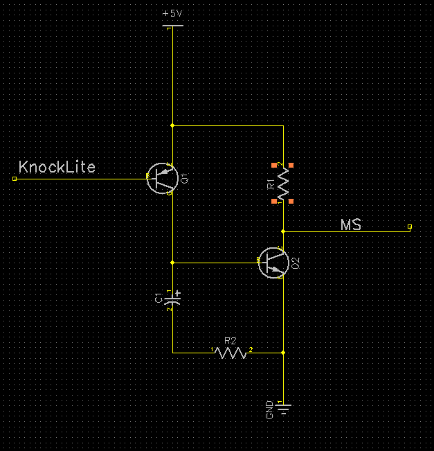
When the knocklite pulls down the base of the PNP, it passes its current through to the NPN's base and charges the capacitor. While the NPN is active, it drains the pullup (the MS gets the low/knock signal) and is kept open for a short time by the cap even after the knocklite returns to a positive voltage (allowing the MS to grab the signal)
The graph on the right is the base of the PNP getting pulled down, the graph on the left is the output the MS would see.
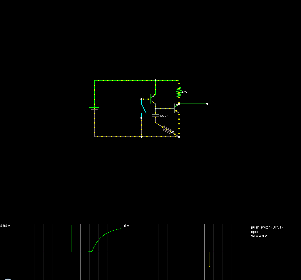
Reply
0
0
Junior Member
Joined: Jun 2009
Posts: 126
Total Cats: 4
Thanks Jeff appreciate that, could something like this be built in the proto area of the diypnp? I will try to get someone here in the UK to help me build it (give me something mechanical and I'm OK!).
Barry
Barry
Reply
0
0
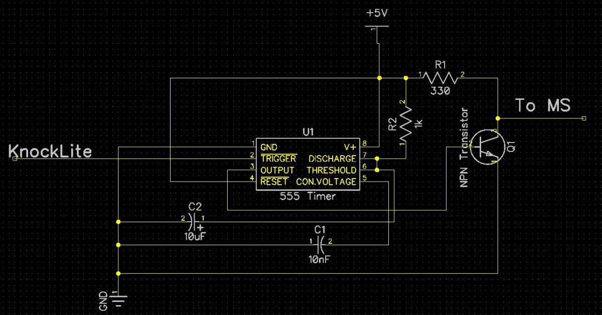
You might have to play with the values a bit to get it to hold down the signal for the correct amount of time. I used a 4.7k pullup on the MS, a 100uf cap, and a 100 ohm between the cap and ground.
Reply
0
0
Junior Member
Joined: Jun 2009
Posts: 126
Total Cats: 4
Brilliant, knowing the knocklite offers 2 warnings, amber for light knock and red for severe knock I suppose the information I now need from TurboXS is:
What is the 5v - 0v pull down time for both warnings.
We would also need to know the minimum 5v - 0v pull down time MS needs to accept the drop in voltage.
If we know these 2 things then I assume the circuit could be built to allow 2 different timing pull rates, say 5 degrees for amber and 10 degrees for severe?
Does that make sense?
Barry
Reply
0
0

Supporting Vendor

Joined: Sep 2006
Posts: 2,332
Total Cats: 67
A good safe minimum time would be 10 to 15 ms.
Reply
0
0
Junior Member
Joined: Jun 2009
Posts: 126
Total Cats: 4
Thanks Matt. Would you know what causes the MS to pull the timing in increments, ie 3,6 or 10 degrees, is it the time delay between 5v-0v-5v or is it dependant on the level of the voltage drop? I assume it is the time that there is zero volts?
Barry
Barry
Reply
0
0
Supporting Vendor
Joined: Sep 2006
Posts: 2,332
Total Cats: 67
It keeps backing the timing off until it stops seeing knock or hits the maximum knock retard. See this link for details.
http://www.msextra.com/doc/ms2extra/...ware.htm#knock
http://www.msextra.com/doc/ms2extra/...ware.htm#knock
Reply
1
1
Junior Member
Joined: Jun 2009
Posts: 126
Total Cats: 4
Reply
0
0


Thread
Thread Starter
Forum
Replies
Last Post
StratoBlue1109
Miata parts for sale/trade
21
Sep 30, 2018 01:09 PM


