
CAN Bus Termination: AEM to MS3


Thread Starter
Junior Member
iTrader: (4)
Joined: Apr 2014
Posts: 173
Total Cats: 16
From: Toronto, Canada
Gentlemen,
Should I use 120Ohm resistor in parallel with AEM 30-0300 X-Series AFR Gauge connected to MS3Pro PNP to terminate CAN bus?
Please advise
Update:
I have received an answer from Matt Cramer, DIY support:
"The MS3Pro has a 120 ohm resistor at its end. It looks like you'll need to put one on the AEM unit as well.
Matt Cramer.DIYAutoTune Support".
Last edited by irodd; Sep 22, 2018 at 05:19 PM.
Reply
 0
0

0


I read that as needing the 120 Ohm terminating resistor since there is not one internally. Not quite apples to apples, but I am installing an AIM MXS Strada to my MSPNPPro, and I needed to enable the internal 120 Ohm resistor in the software for the MXS.
Reply
0
0

Senior Member

Joined: Apr 2017
Posts: 1,232
Total Cats: 169
From: Greeley, CO
Nope. All I know is that I didn't use one when connecting that exact wideband to my MS3x which is essentially a MS3pro. There's been some discussion lately about running that wideband on the MS3pro and none of those guys mentioned a resistor either.
Reply
0
0

You should add the resistor. It might work without the resistor, but there should be a resistor. You can even buy nice connectorized 120 Ohm termination resistors so you don’t have to mess with soldering stuff into your harness.
DTM termination resistor for $5
DTM termination resistor for $5
Reply
0
0
Thread Starter
Junior Member
iTrader: (4)
Joined: Apr 2014
Posts: 173
Total Cats: 16
From: Toronto, Canada
I have it connected without termination resistor too, and it is still working.
but I believe the termination in CAN Bus networks is for signal quality (and some other reasons).
From my SAAB Can bus expirience - there were lot of bricked ECUs during reflashing via can bus without termination resistor.
but I believe the termination in CAN Bus networks is for signal quality (and some other reasons).
From my SAAB Can bus expirience - there were lot of bricked ECUs during reflashing via can bus without termination resistor.
Reply
0
0
Joined: Sep 2012
Posts: 4,560
Total Cats: 1,143
From: your mom's house phoenix, AZ
That's exactly what its for, signal quality. It keeps the end of the CAN run from becoming an antenna, and makes the input impedances play nicely with whatever buffer or I/O chip is in the CAN equipment.
Reply
1
1
Thread Starter
Junior Member
iTrader: (4)
Joined: Apr 2014
Posts: 173
Total Cats: 16
From: Toronto, Canada
I have received an answer from Matt Cramer, DIY support:
"The MS3Pro has a 120 ohm resistor at its end. It looks like you'll need to put one on the AEM unit as well.
Matt Cramer.DIYAutoTune Support".
"The MS3Pro has a 120 ohm resistor at its end. It looks like you'll need to put one on the AEM unit as well.
Matt Cramer.DIYAutoTune Support".
Last edited by irodd; Sep 22, 2018 at 05:19 PM.
Reply
0
0

Junior Member
Joined: Jun 2010
Posts: 295
Total Cats: 43
From: Minneapolis, MN
I know this is old and I've searched all over but am still confused as to exactly where a terminating resistor needs to be placed. My two AEM UEGO canbus wires attach directly to the MS3Pro wires at the options connector. Matt said the MS3 has a 120 Ohm resistor so... is that not the end of the run? AEM to MS3 w/ terminating resistor?
Thanks!
Thanks!
Reply
0
0

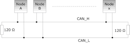
Think of canbus like a loop, broken at each end by the terminating resistor.
The very first and the very last thing connected to the network needs the terminating resistor. ECUs typically have a terminating resistor built in, whereas gauges do not.
Canbus is a differential signal, the state of each wire is important for determining a zero or a one. Without the termination, signals can reflect and cause issues determining those states. I say can, because it's not going to be an issue on a very short run or at lower baudrates. There are also restrictions on stub lengths, too.
When a bus is properly terminated you should be able to measure the resistance between CANL and CANH, and it should be about 60 ohms. Not always though, I use dual P mosfets for MCU toggleable termination. If you've got something that lets you set termination in software this test might not work.
Reply
1
1
Junior Member
Joined: Jun 2010
Posts: 295
Total Cats: 43
From: Minneapolis, MN
I apologize if my answer sounds rude, I don't mean it to be...so according to AEM and Matt, an X-series UEGO owner installation onto an NA/NB Miata (NC?) needs to cut open the outer insulation to access the wires near the inline controller or gauge and add a terminating resistor across the Canbus wires? Doesn't that put the controller/gauge outside the resistor unless you add wire to each and terminate across those added wires...or does it not matter since it's all parallel? There is no canbus network and nobody has really answered the question as to how to properly accomplish the task. This thread came closest but still not quite there. Maybe I'll email AEM directly, best from the horse's mouth, right?
Reply
0
0
The resistor can be outside the gauge or sensor, there's no electrical difference between that and a stub like Node B in the pic above. You could imagine moving Node X's connection on the bus to the very ends of the resistor on the right, wouldn't change a thing in function electrically.
You would not want the terminating resistor more than the longest allowable stub length away from the gauge.
You would not want the terminating resistor more than the longest allowable stub length away from the gauge.
Reply
1
1
Junior Member
Joined: Jun 2010
Posts: 295
Total Cats: 43
From: Minneapolis, MN
"longest allowable stub length" What? You're talking to somebody with a Master's Degree in Violin Performance and not quite an associate degree in computer programming from 20+ years ago. I searched quickly this morning and might ask my mechanical engineering brother that designed fuse panels and wire harnesses over the last decade but he hadn't even heard/read about PID controllers so...
I have the AEM X-series guage controller (30-0300) installed in my '04 MSM. I recently purchased the inline controller so I can replace the gauge and tuck the controller up under the dash as I get closer to being properly tuned. I don't want a flashy gauge attracting attention from boy racers and thieves and it's difficult to read with the top down. I'll use MSDroid with my phone mounted at the central vents when I want to monitor AFR and other data. I am concerned about signal quality thus my questions about how/where to install the resistor. I guess I'll open the outer wire sleeve as close as I can to the controller to access the canbus wires. Then solder a resistor across them or two wires to slightly extend out from the wire cover so I can more easily insulate everything. Soldering is fine but I'd rather not totally cut the canbus wires. I don't want to cause more problems that I'm solving and many say it works fine, as does mine, without any resistor on the AEM side of the wire run.
Thanks
Reply
0
0
To keep it simple, some standard somewhere says that your termination resistor should be no more than 0.3M from the transceiver/gauge. Some other standards will say 3M, others say more yet. As you seem to know, in some cases you don't even need it. To get more complex, canbus is self clocking as well as arbitrating between transmitting nodes priority, so propagation delay can desync a node from valid data or possibly crash the whole bus if something tries talking over something else. All that means no valid data is transferred, not much else. Canbus messages have CRCs or error checking, this ain't analog.
To have it proper you should do what you describe, 120 ohm resistor between CANL and CANH, preferably within 0.3M of the gauge.
If you want to get really fancy there are lots of terminating resistor connectors, like this one...
Deutsch 2P DTM 120 Ohm Terminating Resistor
You could track down the socket and terminals, just dual crimp the wires instead of soldering. That's how I've seen some OEM's do.
Reply
1
1

Sorry if I'm missing something here but I've got a 99 w/ an MS3Pro, and am running an AEM 30-0300 using CAN. I've just got the CAN H/L wired straight to the board and only had to set the "29bit Megasquirt CAN Enable" to Off to make it work, no resistor aside from what I assume is on the board of the MS3Pro.
Reply
0
0
If you had anything more complicated than what's probably less than 0.3M of canbus with only two transceivers it might not work. But it does, doesn't make it right, but it is what it is.
Maybe we can get Joe in here to tell us about eye patterns?
https://www.researchgate.net/figure/...fig3_224060363
Canbus "samples" the state of the lines at a fixed percentage usually, if the bus is still ringing it might not capture the proper state. The resistor helps with the ringing, really all there is to it.
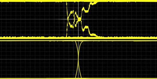
The upper image is an unterminated canbus network, while the lower has proper termination.
Maybe we can get Joe in here to tell us about eye patterns?
https://www.researchgate.net/figure/...fig3_224060363
Canbus "samples" the state of the lines at a fixed percentage usually, if the bus is still ringing it might not capture the proper state. The resistor helps with the ringing, really all there is to it.
The upper image is an unterminated canbus network, while the lower has proper termination.
Reply
1
1
Junior Member
Joined: Jun 2010
Posts: 295
Total Cats: 43
From: Minneapolis, MN
Thank you very much. You've been super helpful. My gauge controller is mounted in the left side of the glove box on a modifed, adjustable mount so I can pivot it down to hide when I'm not using it. I left the wire length long, might have shortened it a little but I'm fairly certain it's at least 1M to the MS3. I'll correct this when I install the inline controller that will replace the gauge. The O2 sensor cable length is very long so it'll be easy to mount the inline controller above the driver's feet with a few wire tires. Then CANH and CANL wires will be as short as possible. Plus, installing a resistor to the controller while it's on a bench is much easier than trying to modify the gauge controller that's already mounted in my car. Now that I think about it, the 30-0300 gauge has two wire harnesses that plug into the back of the gauge. Simply unplug the one with the CANH, CANL, and power/ground wires and you can easily put a resistor very close to the gauge/controller.
Very soon my car will be parked in my garage for Winter season. I'm slowly making progress tuning the MS3 but want to minimize any signal quality issues. It looks like the first link above might be that same terminating resistor but there is a lot more information to work with. I'll try to find a matching connector and crimping sounds better than soldering. I always try to avoid permanently altering wire harnesses going so far as to buy plugs to make jumper harnesses. With the modification on the jumper harness (DRL module for one example), reverting back to the untouched OEM setup is plug and play if the modification is no longer wanted by you or a future owner.
EDIT, I looked and couldn't verify the recommended connector from the datasheet would fit. Visually it didn't look like they'd fit together and I don't see terminal data. The first link to this terminating resistor on Mouser website mentions not having to solder but I don't see how. I guess I'll buy and solder a 120 Ohm resistor in but now I have no clue which type/wattage to buy. I know I don't want SMD. LOL
Very soon my car will be parked in my garage for Winter season. I'm slowly making progress tuning the MS3 but want to minimize any signal quality issues. It looks like the first link above might be that same terminating resistor but there is a lot more information to work with. I'll try to find a matching connector and crimping sounds better than soldering. I always try to avoid permanently altering wire harnesses going so far as to buy plugs to make jumper harnesses. With the modification on the jumper harness (DRL module for one example), reverting back to the untouched OEM setup is plug and play if the modification is no longer wanted by you or a future owner.
EDIT, I looked and couldn't verify the recommended connector from the datasheet would fit. Visually it didn't look like they'd fit together and I don't see terminal data. The first link to this terminating resistor on Mouser website mentions not having to solder but I don't see how. I guess I'll buy and solder a 120 Ohm resistor in but now I have no clue which type/wattage to buy.
I know I don't want SMD. LOL
Last edited by Jesse99James; Nov 1, 2021 at 08:47 PM. Reason: change of plans...
Reply
0
0


