
Post your DIY aero pics
 02-24-2012, 11:53 PM
#1
Try to use this template if possible to help others learn (and copy)
Dollars spent:
Hours spent:
How effective:
0=slower, 1, no improvement, 2 =slightly better,3= big improvement
Materials used:
URL, brand name, material type
Size/thickness of materials:
.060", 3/16" etc
Bracket location:
Tracks tested on:
Race/TT class built for:
To keep the thread clean DO NOT QUOTE IMAGES.
No fuzzy, out of focus cel phone pics. It's 2012. If you can't take a decent digital image and post it on a forum, you lose man points.
Non-Miatas OK as long as it's DIY. Mixing OEM or aftermarket aero with DIY is fine. In other words, don't show us a pic of your new Garage Vary copy on your street car at stock ride height with daisies.
__________________


Reply
 1
1

1
02-25-2012, 12:07 AM
#2
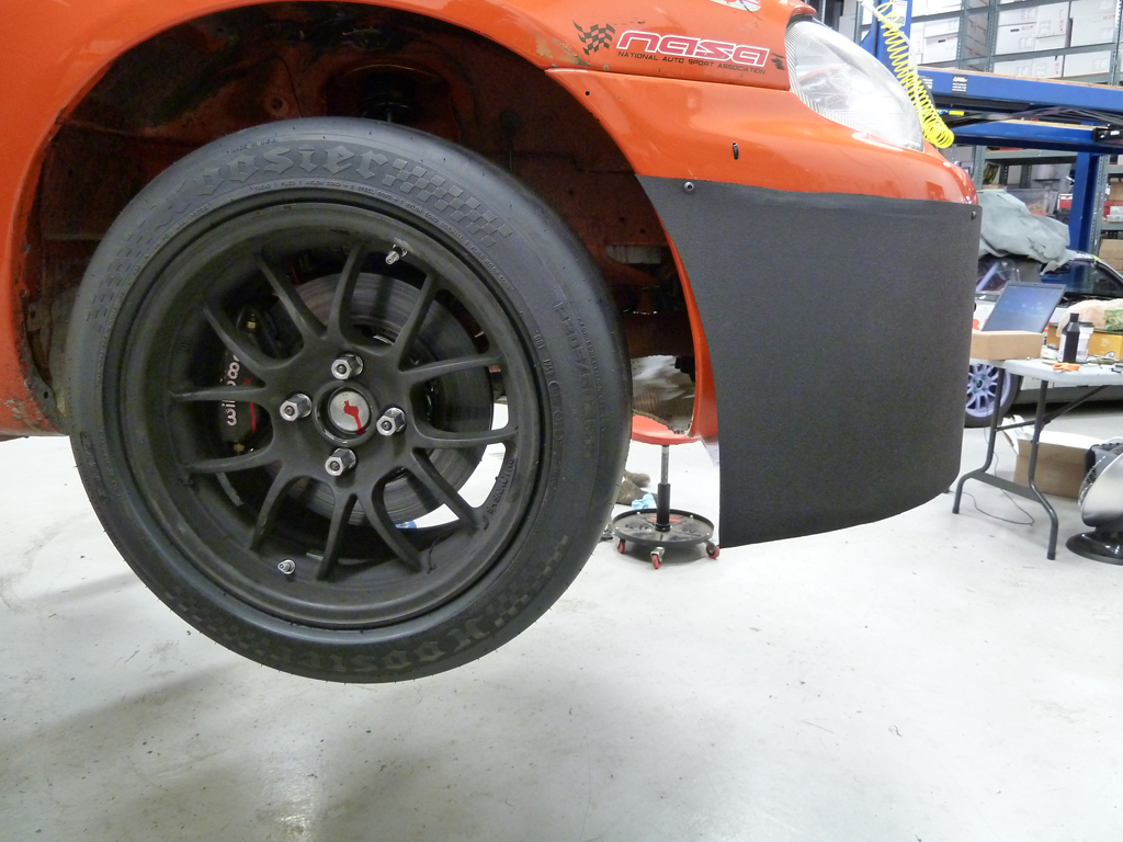
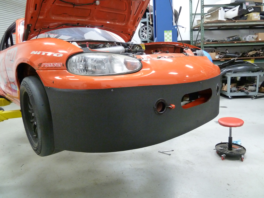
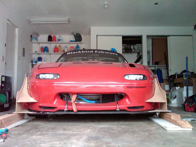
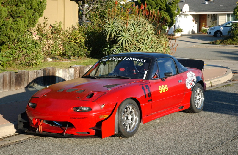
~$60 spent
3 hours
3 for lowered drag, probably 2 for reduced lift
corrugated plastic and ABS sheet from www.sign-mart.com
coroplast was 3mm white for undertray. ABS sheet was .060 black
Air ducts from Aircraft Spruce
Machine thread screws into subframe though undertray for rear.
Dam had riv-nut inserts in OEM bumper skin then 3m machine screws through dam to hold it on. Ducts are zip tied in place through skin.
Testing this weekend at Auto Club Speedway in Fontana, CA. Looking for less drag than OEM dam we ran at T25 and most of last season.
NASA E1/PTC/TTC. 3 points. It's temporary until we get our complete race nose finished.
__________________
Last edited by emilio700; 02-25-2012 at 12:20 AM.
Reply
3
3
02-26-2012, 04:47 PM
#3

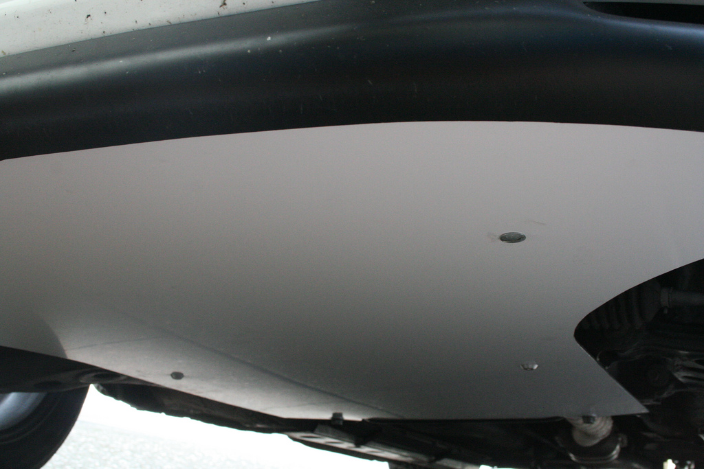
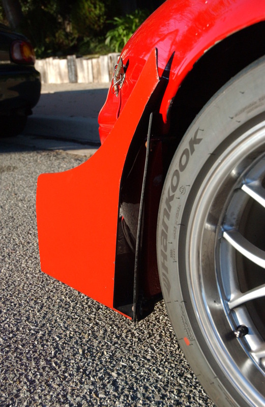
~ $60 spent
5 hours or so spent
?drag, 3 for lift
made of 3 mm dibond
Mounting:
uses oem rear subframe brace bolts, oem belly pan mounting points at steering rack. in the front i have L brackets that mount to the AC condenser bracket and have Dzus fasteners holding the tray on.
havent gotten it on the track yet but it feels like the front is more planted on the highway 75mph+
my car is a DD/weekend track car.
Reply
2
2
 02-27-2012, 03:48 AM
#5
Junior Member

Join Date: Aug 2009
Posts: 186
Total Cats: 2
mine started like this:
eventually did more, aiming for drag redux, lift redux second. (stock B6 engine)
birch ply 1/4" splitter became undertray when i added an airdam in front of it (minimize air underneath, but to allow for bottoming out without damage)
at the rear end, 2' wide x 26" long diffuser @ 6.5* and 9.8*... strings of yarn were tested at various stages of development which led to corrugated plastic aft of the chassis floor to the end of rear subframe. Entire rear floor covering a span of 44" end to endNext is complete rear diffuser spanning bumper to bumper. Have also tried fins on the HT window, with plans towards fins from the windshield frame back.
I've posted plenty pics in another thread, it might be redundant putting it here so here's my video of the end result so far.
MUTE MUSIC PER PREFERENCE
PAUSE AT:
0.39 for front end aero
1:05 for before/after rear end aero
doing coolant reroute and rad swap eventually, will replace oem undertray with corrugated plastic. currently have post-rad ducting as testing but no vent on hood yet.
total drag overall has decreased (objectively)
steering much heavier at speed, very balanced now, biased to slight understeer.
lift has drastically been reduced at speeds 80-90. anxious for another trip to BW 13CW to see how it does.
I dont have complete cost etc as it's been a long time project. (multiple revisions)
as such, can remove post if need be.
Last edited by greeenteeee; 02-27-2012 at 04:06 AM.
Reply
0
0
03-01-2012, 10:38 PM
#7
Downforce on undertray
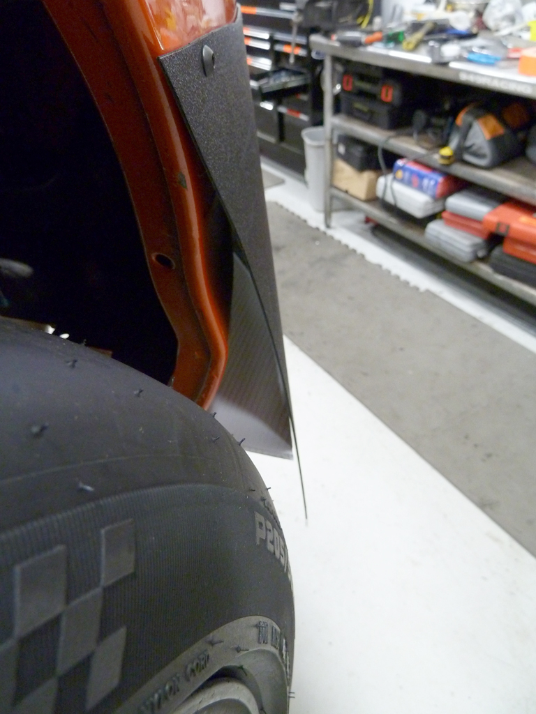
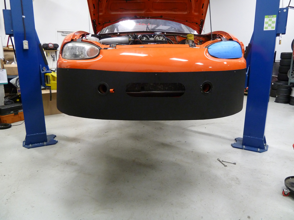
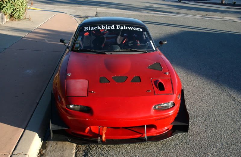
Saturday the one in the first set of pics didn't last at 130mph. It was .060 ABS and was too flexible, fllaped around and destroyed itself. The 6mm coroplast undertray got sucked down from under the dam and ground itself to bits on the T1-2 banking at ACS. So for Sunday we went back to the shop and made a new one from slightly thicker .090 ABS and it held up. We also increased the undertray to 10mm thick corrugated. We didn't brace the undertray and again, it got sucked down and ground on the pavement at about 130mph.
V3 of this dam has added attachment points all the way to the forward edge of the tray to help prevent it getting sucked down. The undertray meets the dam about 2" up from the bottom so it creates a little suction behind the dam. That was our intention but the forces were much more than we expected so it took a few tries to make the undertray rigid enough. Surprised us as there is no splitter at all. Having the undertray meet partway up the airdam also allows the bottom edge of the dam to flex a bit when loading/unloading the car.
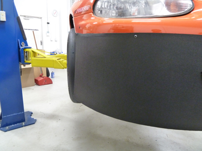
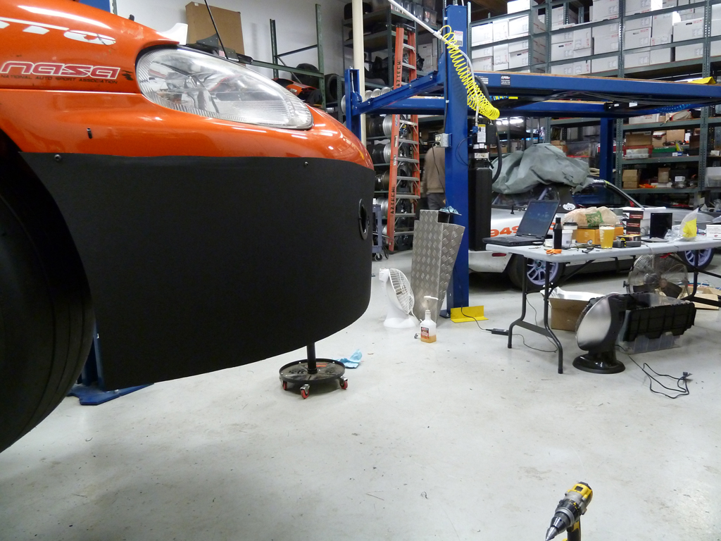
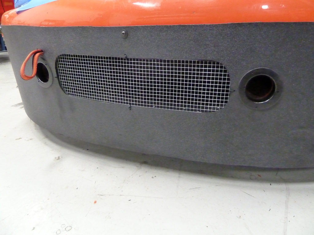
Rad Inlet plenum
We then fashioned a plenum between the mouth in the dam and the radiator. Without it, the airflow was really disrupted as it goes through the mouth, with plenty of little leaks here and there. The plenum solves all that. Easy enough to cut and bend the plastic to make a simple smooth venturi shape that terminates at the rad core. Sorry I didn't get a pic of the plenum before we stuck the grill on there.
Grill and mesh choice
We typically make grills from three meshes of different open ratio. Basically cool and hot weather. With a reroute, it's easy to overcool the engine to the point that the oil doesn't get hot enough. The more closed it ism the less aero drag and more downforce on the front end.
Wire mesh from mcmaster.com
9217T41 81.5% open area hot weather (pictured)
9641T241 61.6% open area warm weather
9227T632 44.8% open area cold weather, what we ran at T25.
Saturday the one in the first set of pics didn't last at 130mph. It was .060 ABS and was too flexible, fllaped around and destroyed itself. The 6mm coroplast undertray got sucked down from under the dam and ground itself to bits on the T1-2 banking at ACS. So for Sunday we went back to the shop and made a new one from slightly thicker .090 ABS and it held up. We also increased the undertray to 10mm thick corrugated. We didn't brace the undertray and again, it got sucked down and ground on the pavement at about 130mph.
V3 of this dam has added attachment points all the way to the forward edge of the tray to help prevent it getting sucked down. The undertray meets the dam about 2" up from the bottom so it creates a little suction behind the dam. That was our intention but the forces were much more than we expected so it took a few tries to make the undertray rigid enough. Surprised us as there is no splitter at all. Having the undertray meet partway up the airdam also allows the bottom edge of the dam to flex a bit when loading/unloading the car.
Rad Inlet plenum
We then fashioned a plenum between the mouth in the dam and the radiator. Without it, the airflow was really disrupted as it goes through the mouth, with plenty of little leaks here and there. The plenum solves all that. Easy enough to cut and bend the plastic to make a simple smooth venturi shape that terminates at the rad core. Sorry I didn't get a pic of the plenum before we stuck the grill on there.
Grill and mesh choice
We typically make grills from three meshes of different open ratio. Basically cool and hot weather. With a reroute, it's easy to overcool the engine to the point that the oil doesn't get hot enough. The more closed it ism the less aero drag and more downforce on the front end.
Wire mesh from mcmaster.com
9217T41 81.5% open area hot weather (pictured)
9641T241 61.6% open area warm weather
9227T632 44.8% open area cold weather, what we ran at T25.
__________________
Reply
1
1
03-02-2012, 11:48 AM
#8

Been keeping up with this thread and information about your NA front air dam for SuperMiata.
Curious to know if adding a front air dam to a mostly neutral car without adding a wing out back will create a car that is prone to oversteer? If so, will the balance be off far enough where I wouldn't be able to gain balance again through adjustments to sway bars, dampening, tire pressures, etc. Thanks.
Also, are there any other solutions that make a significant difference to positive rear downforce or negative rear lift other than a big wing? Thinking rear diffuser, AutoX type trunk spoiler, etc.
Reply
0
0
03-07-2012, 11:43 AM
#10

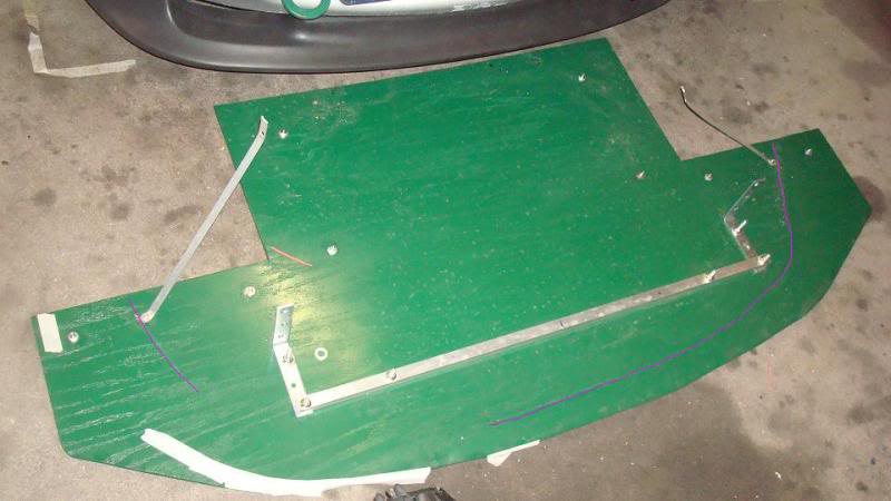
Dollars spent: 0
Hours spent: 2
How effective: not tested yet
Materials used: birch ply
Size/thickness of materials: 12mm
Bracket location: 5 10mm bolts on subframe holding factory undertray on, enlarged for 10mm bolts
Tracks tested on: non yet
Race/TT class built for: weekend lapping
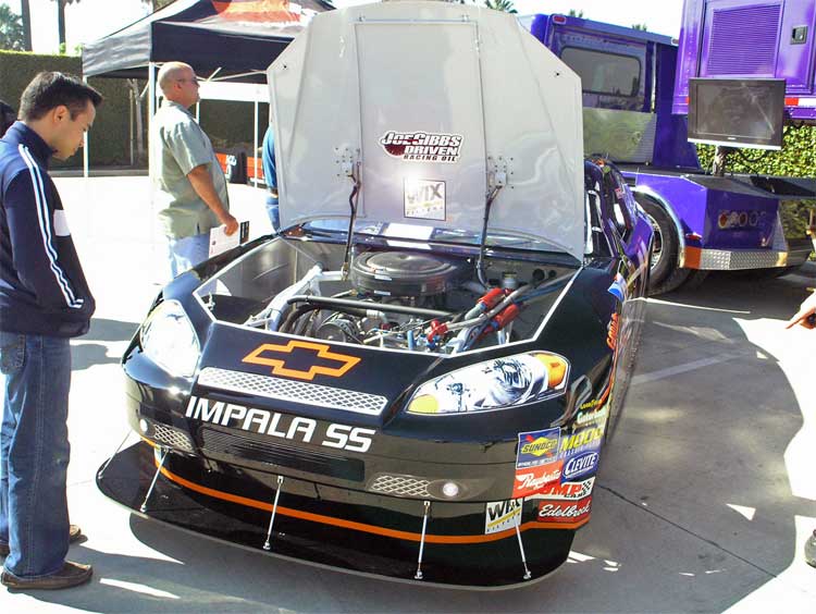
The guy that cut this for me says the shape is better than following the curve of the bumper...wtf do I know, but we'll find out soon. Wish I had a water jet at home. I just have to attach the aircraft cables.


Apparently the guy likes Nascar
Hours spent: 2
How effective: not tested yet
Materials used: birch ply
Size/thickness of materials: 12mm
Bracket location: 5 10mm bolts on subframe holding factory undertray on, enlarged for 10mm bolts
Tracks tested on: non yet
Race/TT class built for: weekend lapping
The guy that cut this for me says the shape is better than following the curve of the bumper...wtf do I know, but we'll find out soon. Wish I had a water jet at home. I just have to attach the aircraft cables.
Apparently the guy likes Nascar
Last edited by dgmorr; 03-08-2012 at 09:22 AM.
Reply
0
0
 03-08-2012, 01:47 AM
#12
Supporting Vendor

iTrader: (3)

Join Date: Jul 2006
Location: San Diego
Posts: 3,303
Total Cats: 1,216
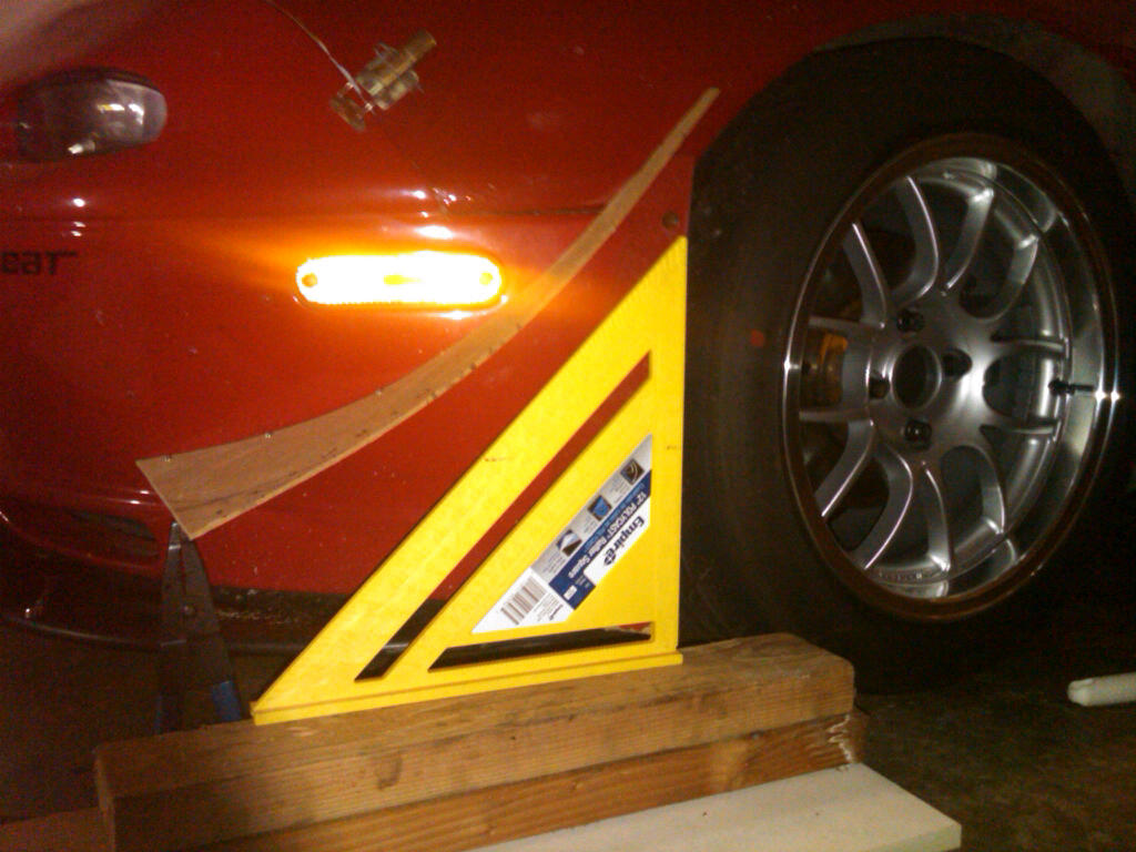
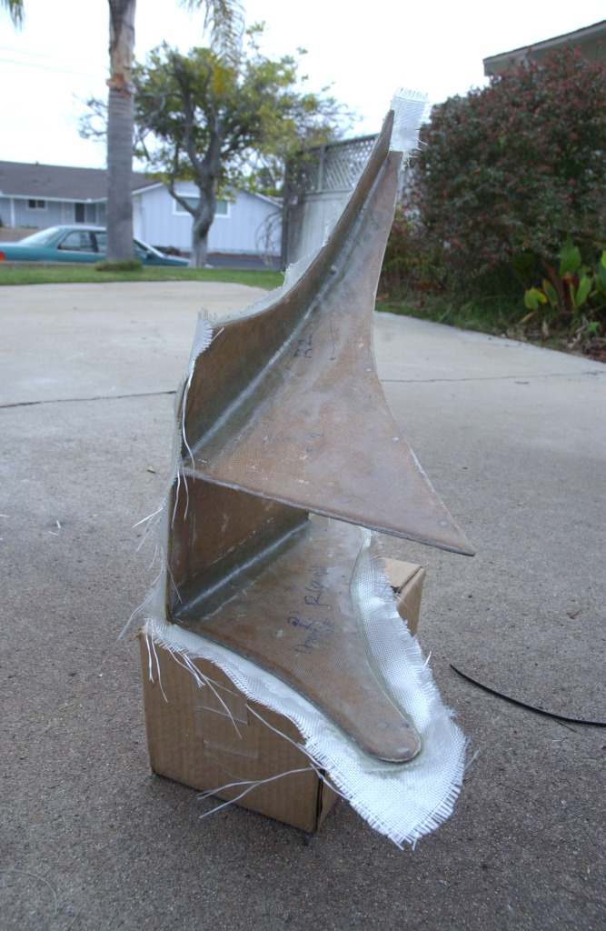
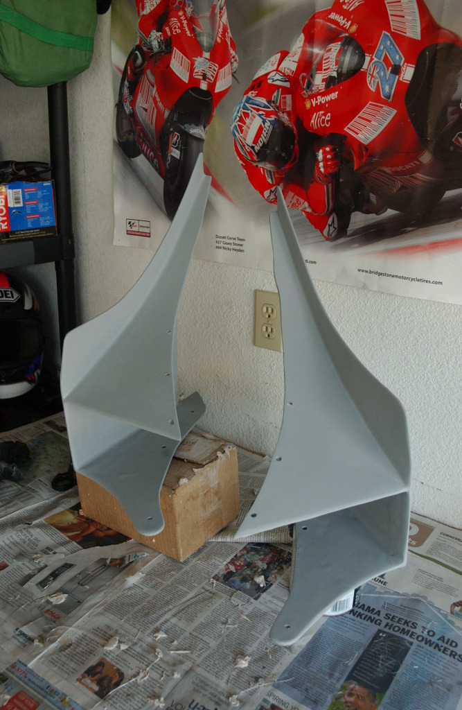
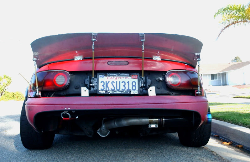
Dollars spent: $50
Hours spent: 20
How effective: 2 - balances the rear spoiler out and large enough that I can feel its effects at realistic speeds. Because it is DIY and I'm no engineer, I'm sure the design could be improved, so it doesn't get a 3.
Materials used: 1/16" MDF sandwiched between 2 layers of fiberglass, 3 layers in the angles
Bracket location: Mounts to bumper w/ little L brackets, and bolts to splitter
Tracks tested on: SOW and several autocrosses
Race/TT class built for: Miata Challenge, if any. Will be at Chuckwalla end of this month to try it out some more.

Reply
1
1
03-08-2012, 01:56 AM
#14
Supporting Vendor
iTrader: (3)
Join Date: Jul 2006
Location: San Diego
Posts: 3,303
Total Cats: 1,216
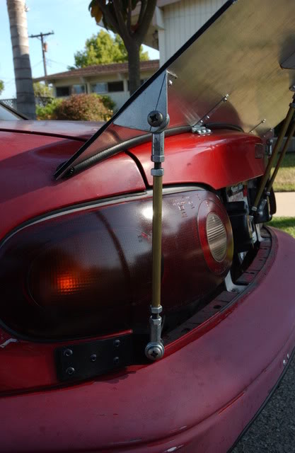
Dollars spent: $110-ish
Hours spent: 10
How effective: 2 - did this before the canards, and it did enough to unbalance the car above 50mph. The canards balanced it out. Still, in many ways it could be improved.
Materials used: Alumalite, aluminum L bar stock, rivets, struts pieced together from hardware store materials
Size/thickness of materials: 6mm alumalite
Bracket location: attaches to trunk with triangular gate hinges
Tracks tested on: Chuckwalla, SOW, several autocrosses
Race/TT class built for: Miata Challenge, if any
Reply
0
0
03-08-2012, 10:18 AM
#16

Just make sure it is securely mounted to the frame of the vehicle not just a plastic portion of the bumper which will flex. If it's rigidly mounted and well supported then the downforce produced will be better translated as increased vertical load on the tires. I've seen many instances of folks attaching splitters in such a way that the majority of the possible downforce is likely lost in deflection of the mounting setup.
Reply
0
0
03-08-2012, 10:29 AM
#17

^Its interesting you mention deflection as bad, considering the whole last season or two of F1 people have been complaining that RB's front wing is deflecting beyond the minimum height and giving them more downforce. Care to explain further?
Perhaps the area of deflection is whats at question here?
Perhaps the area of deflection is whats at question here?
Reply
0
0
03-08-2012, 05:16 PM
#18
^Its interesting you mention deflection as bad, considering the whole last season or two of F1 people have been complaining that RB's front wing is deflecting beyond the minimum height and giving them more downforce. Care to explain further?
Perhaps the area of deflection is whats at question here?
Perhaps the area of deflection is whats at question here?
The goal with the front wing deflection on the red bull was to get the front wing element closer to the ground which would produce more downforce. The mounting of the wing however was not designed to deflect. If it was, then the downforce produced would be wasted and not translated into increased vertical load on the tires.
This article actually explains it quite well.
http://scarbsf1.wordpress.com/2010/0...ls-front-wing/
So yes, deflection of the actual aerodynamic device can be used to your advantage, but if your goal is more vertical load on the tires, then the force it's generating has to be translated to the wheels effectively.
If your splitter makes actual downforce and that downforce is only used to bend your bumper, then it's really not helping you at all is it?
Reply
0
0
03-08-2012, 10:04 PM
#19
Elite Member
iTrader: (15)

Join Date: Dec 2007
Location: San Antonio, Texas
Posts: 4,847
Total Cats: 27
Well, strictly speaking, as long as the bumper eventually stops deflecting, then the downforce is still being translated to the wheels. Static loads. And nothing is completely rigid, so no matter how beefy your structure is, it still moves under load.
But, point made. Structurally speaking these aero devices should be well attached to the chassis.
But, point made. Structurally speaking these aero devices should be well attached to the chassis.
Reply
0
0


