When you click on links to various merchants on this site and make a purchase, this can result in this site earning a commission. Affiliate programs and affiliations include, but are not limited to, the eBay Partner Network.
Work in progress- Brake ducts in GV lip for SADFAB
Hi All,
I am working with @hi_im_sean on some brake cooling ducts for GV lips and possibly R package lips (haven't scanned the r package lip yet, need to see if there is enough cross section for 2.5" outlet).
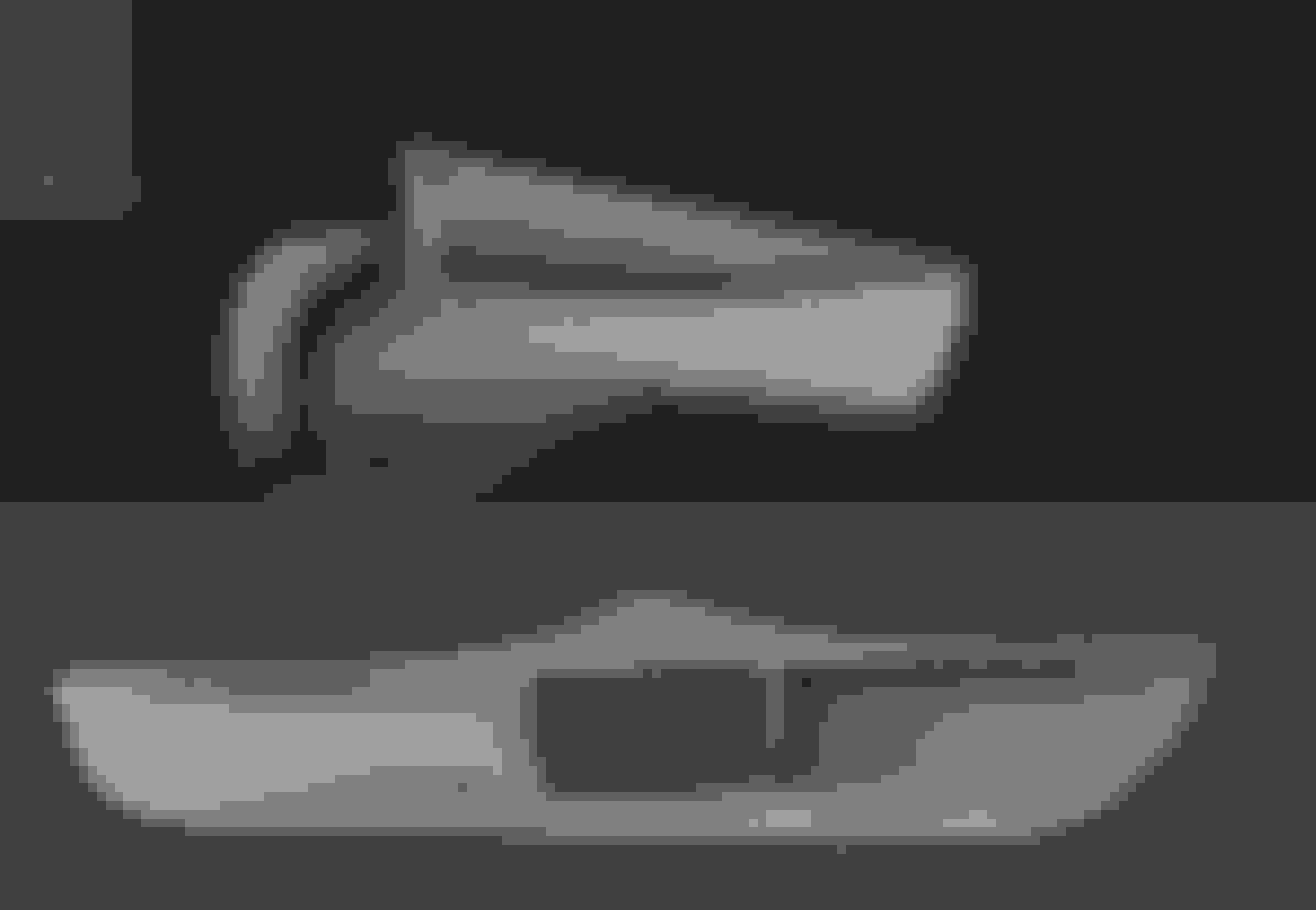
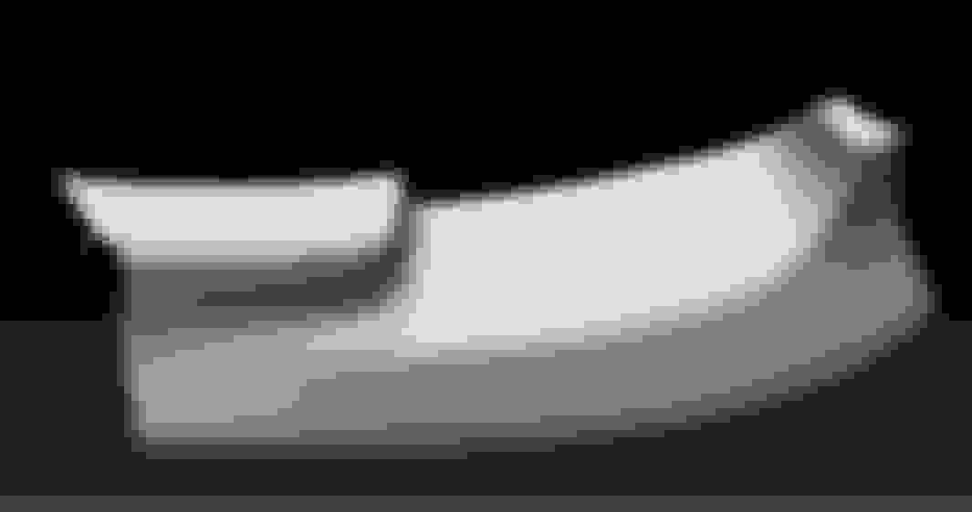
So far I have scanned the GV lip:
And begun basic measurements for the duct:
I'm looking for feedback on ways to mount it. I think we are going to do 4 countersunk fasteners from the lip to the duct. We might need some support from the top as well. A well zip tied hose near the outlet would provide good additional support.
The outlet is currently 2.5" but there is enough area to support up to a 3" duct if anyone has a use for that.
Also, is there anything specific people need for the outlet location? IC piping clearance? Prefer it come out at an angle towards the wheel slightly?
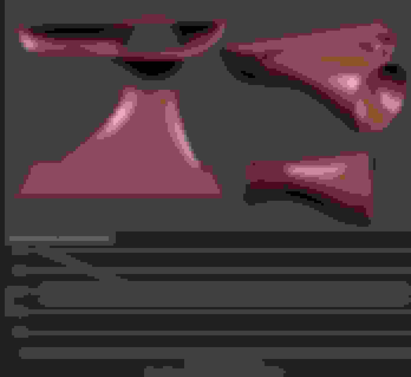
First pass at a rough design. In some areas with will be a dual wall part. One wall that hugs the inside of the lip for solid fit, another inner wall that does the airflow. I roughed in an inner wall and measure the cross sections. The green line is my target and since most of my issues are after the duct clears the lip, I should have no issues hitting it. There will be some amount of a balancing act balance between blending shapes smoothly to keep laminar flow, and making the size transitions follow a nice curve.
I bought the 3d printed ones from another enthusiast but found them lacking in the mounting department. Hard to get a screwdriver in the mouth of the inlet and even harder to get a drill in there.
Would it be possible to have the bottom lip go beneath the gv lip and allow the holes to be drilled through the GV lip from below and screws or pop rivets used from above or below?
My intent is to use allen head countersunk machine screws and nuts, probably nylocks. So you can hold the screw with an allen key in the mouth of the opening and tighten the nut above and below the inlet and bumper skin/lip respectively. There is no reason you couldn't use rivets with the same inlet mounting design. Other than being able to mark the holes for drilling, I'm not sure how tucking the lower edge of the duct under the lip will help anything? We can probably make drill templates if that's the case, or maybe tucking it under is better; I'd need to look at the lip again when I get home to see how that'd work. Maybe even sandwich the lip between 2 lower edges of the inlet, although that may complicate printing.
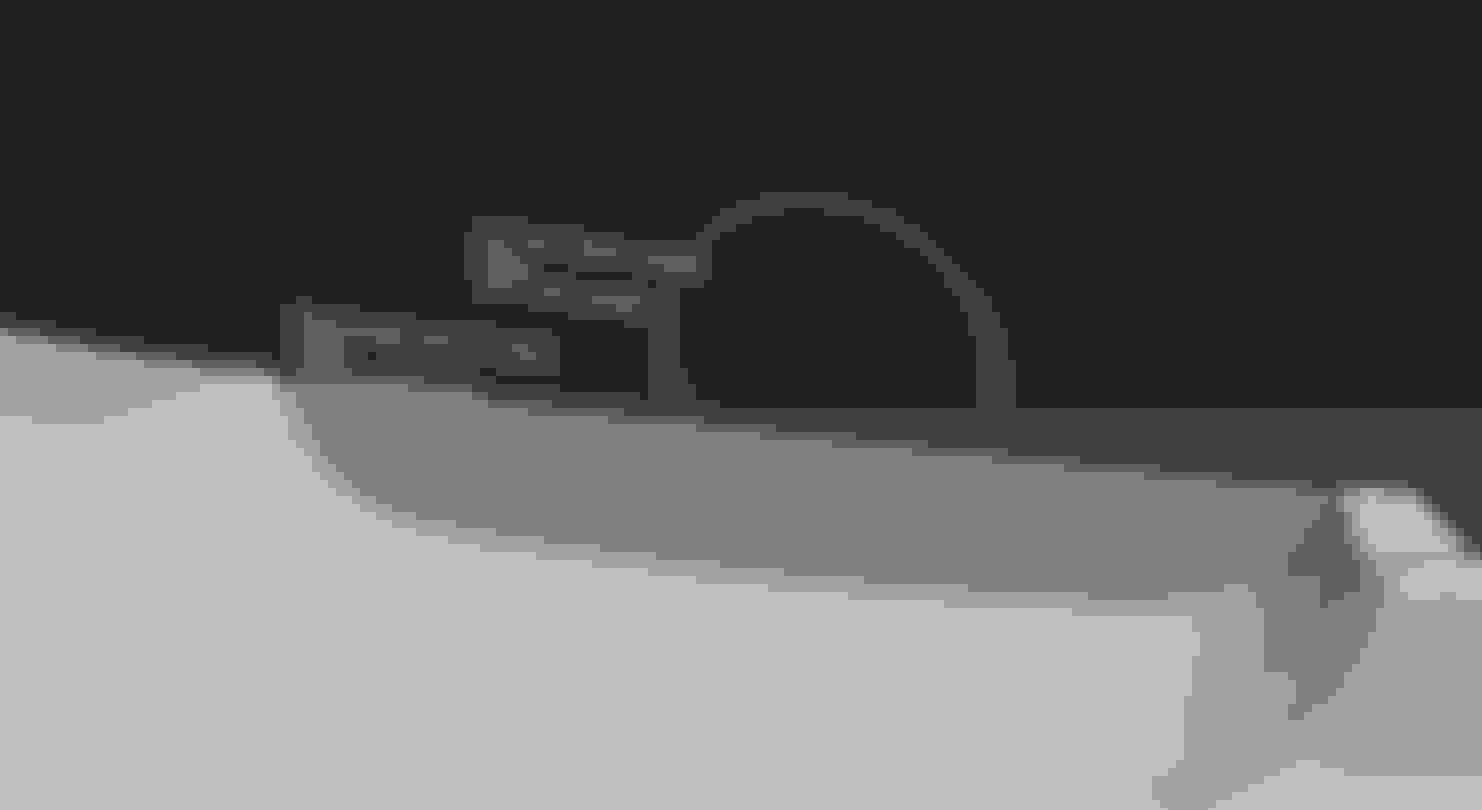
Another pass at it. I moved the opening away from the center line of the car to better clear IC piping. I also angled the duct out 5 degrees. I'm going to rescan the lip after mounting it because I'm unsure of the exact curvature and available space with the bumper. Also if you look at the graph, the cross sections are much better now. Ideally I will take some of the shoulder out of that curvature and make it softer. Also this is going to feed into corrugated ducting so getting that last bit of flow optimization is probably a waste of time.
I unscrewed it from the bumper cover and angled it downward but it was a little awkward to mark the spots where I needed to drill with a sharpie through the little holes. I didn't drill or screw the top holes for this reason.
New idea: If the duct flared out in front of the hole and was screwed or riveted from the front it would be ideal.
I'm a little concerned people won't be willing to drill holes in the front of their bumpers where it will be visible if they ever remove the ducts.
It's really low on the bumper. The same black pop rivets can be painted to match the body color with a tiny bit of touch up paint if someone really cared. Brake ducts are for track cars anyway. The number of track cars going back to stock is miniscule.
I could be misunderstanding and/or this maybe not be a viable solution since the majority of client's would likely be track focused with speeds at 100+mph, but would a generous use of double sided tape work? That could go in addition to the new idea posted by Six and conceivably work in my head.
I think body mounting tape would work if the fit was very good. Based on the design I'm working on now, the part can't actually be installed or removed unless the lip is pried apart or partially removed. It should be snug and not require that much to be well attached.
I will be getting back to these next week when my printer is up and running again. I'm doing another scan of the lip with it mounted on the bumper since the last design didn't fit well and I think it was a result of the lip being flexible.

 11-18-2017, 01:04 PM


 1
1